UEFI (Unified Extensible Firmware Interface)
BIOS chip
The firmware is located near the south bridge on the Winbond 25064FVA1G chip. All screenshots were taken in version 2.10.1208, brought to normal by the Load optimized Defaults team.
The interface is almost the same as in the solutions of competitors - AMI is AMI. However, according to the status of the product, there are more opportunities here.
|
|
|
|


When entering the BIOS, we see the Extreme Tweaker tab, which leaves no doubt who this product is intended for.
At the bottom of ET is an impressive list of available voltages to change. The adjustment ranges are wide, and when activated, the Extreme OV options become completely huge. A summary of the voltages is given in the table below.
| Voltage | Minimum value, V | Maximum value, V | Maximum value, V (Extreme OV) | Step |
|---|---|---|---|---|
| CPU Manual Voltage | 0,675 | 1,75 | 2,3 | 0,0063 |
| CPU/NB Manual Voltage | 0,5 | 1,55 | 1,9 | 0,0063 |
| CPU VDDA Voltage | 2,2 | 2,8 | 3 | 0,0063 |
| DRAM Voltage | 0,86 | 1,85 | 2,135 | 0,005 |
| NB Voltage | 1,1 | 1,5125 | 2 | 0,0063 |
| NB HT Voltage | 1,2 | 1,5125 | 2 | 0,0063 |
| NB 1.8V Voltage | 1,8 | 2,0075 | 3,0078 | 0,0133 |
| S.B. Voltage | 1,1 | 1,6033 | 1,802 | 0,0133 |
| VDDR | 1,205 | 1,5105 | 1,802 | 0,0133 |


DRAM Timing Control
The DRAM Timing Control subsection allows you to control memory delays.

DRAM Driving Control
If you installed a lot of RAM and the system is not stable enough, you can try increasing the multipliers in the DRAM Driving Control section.

The GPU.DIMM Post subsection allows you to view the status of memory modules and video cards before the system boots (for example, whether they have warmed up after LN2).


DIGI+ Power Control
DIGI+ Power Control contains everything that will help you fine-tune the board's digital power system.


As usual, the Main section allows you to set the time, select your preferred language and set a password to access the settings.

Almost all operations for controlling the components integrated into the board are available in the Advanced section. It does not make sense to consider them in detail, the screenshots speak for themselves.

CPU Configuration


North Bridge\Memory Configuration


SATA Configuration

SATA Configuration\ SB SATA Configuration

USB Configuration

CPU Core On/Off Function

Onboard Device Configuration

Onboard Devices Configuration\ SB HD Azalia Configuration


iROG Configuration


The Monitor subsection allows you to monitor the current state of the system. There is no summary screen, everything is divided into categories. In addition, the section for setting the operating mode of the cooling system was moved here.


temperature monitor

Fan Speed Monitor

Fan Speed Control


In the Boot section, you can traditionally change the priorities of disks during boot and see the list of available drives.

ASUS EZ Flash 2 Utility
Initially, an attempt was made to update the firmware using BIOS Flashback, which, as stated, does not even require an installed processor and memory. After completing the steps listed in the instructions, the BIOS_FLSHBK LED next to the BIOS chip lit up, and we began to wait. Ten minutes later, nothing had changed, so it was decided to restart the system. Terrible did not happen, the microprogram did not deteriorate. No miracle - the BIOS version remained the same. But the built-in BIOS update utility did its job perfectly.

The result of the MyLogo2 utility
By the way, when updating the BIOS from under Windows, it is possible to replace the start image. This function is called MyLogo. The aspect ratio of the picture, judging by the preview in the utility, should be approximately a multiple of 160:97. The 1280x776 picture required a reduction of up to 98% and ended up being compressed to standard 5:4. The requirements for the image could be mentioned in the program or instructions, but no one began to be puzzled by this for the sake of the entertainment function.

ASUS SPD Information

In the ASUS OC Profile section, you can save and load profiles for various operating modes. Eight slots should be sufficient for most reconfiguration needs.

In the GO Button File subsection, you can specify the system settings that will be applied when you click the GO Button. Very convenient for an open stand, not very - in all other cases.

BIOS in EZ Mode
In simplified mode, it is convenient to view summary information. In addition, the younger generation of users will find it easier to work with the BIOS: the setup is reminiscent of working with a utility under Windows.


Shortcuts menu. Not translated into Russian
⇡ Overclocking and stability
System overclocking can be done from the UEFI BIOS, from the operating system using AI Suite II, and even from another computer using ROG Connect technology. The first two methods have been discussed many times, so they are of no interest, and the last one is a unique overclocking opportunity. The first thing that comes to mind is changing the CPU frequency right during subtests, for example, in the 3DMark package. Not fair? Why? This is a regular feature of the board.

It all looks like this: the corresponding feature is activated in the BIOS, a button is pressed on the back panel of the motherboard, and the bundled cable is plugged into the nearest (white) USB port. On another computer, install the ROG Connect client program, connect the other end of the cable ... and here it is, access to all voltages, frequencies and temperatures! Sometimes there were failures: the client module did not show the frequencies at which the CPU and the board worked. When changing any of the parameters, everything returned to normal (the Refresh button did not lead to such an effect).
Not everyone needs such features, but still such boards are rarely bought by those who do not need extended functionality. If such an opportunity did occur, a hardware-software tandem will come to the rescue: AI Suite II and TPU. Available "fast" and "extreme" overclocking.

The first increased the base frequency by 3 MHz and raised the memory frequency to 815 (1630) MHz. According to the system, this is equivalent to a 2% increase. They did not check.

"Extreme" overclocking lasted a little longer and included stability tests.


The screenshots above show the main system parameters before and after activating this feature.
|
|
|
|
|
|
|
|
|
|
|
|
|
|
|
|


Nevertheless, the utility really gives a lot of opportunities for fine-tuning and monitoring. You can evaluate them by clicking on the screenshot of interest. Of greatest interest is the control of the Digi + II power system: you can instantly change not only the voltages, but also the parameters of the phases or the intensity of holding the voltage under load (Load-Line Calibration).

The maximum bus frequency was 359 MHz, but this is obviously the limit of the processor. By the way, on this motherboard, a memory frequency of 1948 MHz is reached, which at the time of publication is second best in the world according to HWBO.
Let's see how the motherboard's power system behaves under overclocking conditions. To do this, we will alternately check the voltages in idle and under load in various Load-Line Calibration modes. The measurement results for the Phenom II X6 1100T Black Edition processor at 4111 MHz are shown in the table below. During testing, the voltages were set to 1.5/1.25/1.57V for Vcore/CPU_NB/DRAM respectively. AIDA64 (soft) will be used as a measurement program, a Victor 86D (hard) multimeter was used to measure the actual voltage. The IDLE and LOAD flags indicate idle and full load states using OCCT 4.3.1. For CPU/NB, there are only three available modes, so there are dashes in the table. The BSOD in brackets is not instantaneous, there was enough time to measure it. The FullAuto column indicates the choice of voltage and LLC level by the motherboard itself.
| Method | Voltage | full auto | Auto | Regular | Medium | high | Ultra High | Extreme |
|---|---|---|---|---|---|---|---|---|
| soft (IDLE) | CPU | 1,356 | 1,512 | 1,464 | 1,476 | 1,488 | 1,488 | 1,512 |
| hard (IDLE) | 1,367 | 1,522 | 1,485 | 1,494 | 1,502 | 1,511 | 1,522 | |
| soft (BURN) | BSOD | 1,56 | 1,404 | 1,428 | 1,476 | 1,512 | 1,548 | |
| hard (BURN) | 1,551 | 1.415 (BSOD) | 1.464 (BSOD) | 1,485 | 1,524 | 1,569 | ||
| soft (IDLE) | CPU/NB | 1,168 | 1,263 | 1,257 | - | 1,263 | - | 1,263 |
| hard (IDLE) | 1,171 | 1,273 | 1,269 | - | 1,272 | - | 1,273 | |
| soft (BURN) | BSOD | 1,296 | 1,27 | - | 1,27 | - | 1,277 | |
| hard (BURN) | 1,298 | 1,285 | - | 1,29 | - | 1,296 |
Based on the results obtained, the High mode turns out to be the most suitable, since it does not overestimate the voltage (although it does allow a slight drawdown under load).
The power supply system of the RAM was deprived of such an opportunity, leaving only the phase control (Optimal / Extreme) and the choice of the PWM frequency:
| Method | Voltage | full auto | Optimal | Extreme |
|---|---|---|---|---|
| soft (IDLE) | DRAM | 1,647 | 1,568 | 1,568 |
| hard (IDLE) | 1,663 | 1,583 | 1,583 | |
| soft (BURN) | 1,654 | 1,568 | 1,568 | |
| hard (BURN) | 1,665 | 1,584 | 1,584 |
As you can see, when using two sticks of RAM, there is no difference between them. The actual voltage is slightly too high compared to the one set in the BIOS.
Of course, our readers know all about overclocking. In fact, many reviews of processors and video cards would not be complete enough without looking at the potential for overclocking.
If you consider yourself an enthusiast, forgive us for some background information - we'll get to the technical details shortly.
What is overclocking? At its core, the term is used to describe a component that runs at higher speeds than its specifications to increase performance. You can overclock various computer components, including the processor, memory and video card. And the level of overclocking can be completely different, from a simple increase in performance for inexpensive components to an increase in performance to an outrageous level that is normally unattainable for retail products.
In this guide, we will be focusing on overclocking modern AMD processors to get the best possible performance based on your chosen cooling solution.
Choosing the right accessories
The level of overclocking success is highly dependent on the components of the system. To begin with, you need a processor with good overclocking potential, capable of operating at higher frequencies than the manufacturer specifies. AMD is currently selling several processors that have fairly good overclocking potential, with the "Black Edition" line of processors directly aimed at enthusiasts and overclockers due to the unlocked multiplier. We tested four processors from different families of the company to illustrate the process of overclocking each of them.
For overclocking the processor, it is important that other components are also selected with this task in mind. The choice of a motherboard with an overclocking-friendly BIOS is quite critical.
We took a couple of Asus M3A78-T (790GX + 750SB) motherboards, which not only provide a fairly large set of BIOS features, including Advanced Clock Calibration (ACC) support, but also work great with the AMD OverDrive utility, which is important for squeezing the most out of Phenom processors.
Selecting the right memory is also important if you want to achieve maximum performance after overclocking. When possible, we recommend installing high-performance DDR2 memory that is capable of clock speeds above 1066MHz on AM2+ motherboards with 45nm or 65nm Phenom processors that support DDR2-1066.
During acceleration, frequencies and voltages increase, which leads to an increase in heat dissipation. Therefore, it is better if your system will run a proprietary power supply that provides stable voltage levels and sufficient current to cope with the increased demands of an overclocked computer. A weak or outdated power supply, loaded "to the eyeballs", can spoil all the efforts of an overclocker.
Increasing frequencies, voltages and power consumption, of course, will lead to an increase in heat dissipation levels, so the cooling of the processor and case also has a significant effect on overclocking results. We didn't want to hit any overclocking or performance records with this article, so we ended up with rather modest $20-25 coolers.
This guide is intended to help users who are less experienced with overclocking processors to enjoy the performance benefits of overclocking a Phenom II, Phenom, or Athlon X2. Let's hope that our advice will help novice overclockers in this difficult but interesting business.
Terminology
A variety of terms, often denoting the same thing, can confuse or even frighten an uninitiated user. Therefore, before we go directly to the walkthrough, we will look at the most commonly used terms related to overclocking.
Clock speeds
CPU frequency(CPU speed, CPU frequency, CPU clock speed): The frequency at which the computer's central processing unit (CPU) executes instructions (for example, 3000 MHz or 3.0 GHz). It is this frequency that we plan to increase in order to get a performance boost.
HyperTransport link frequency: interface frequency between the CPU and the northbridge (for example, 1000, 1800 or 2000 MHz). Usually the frequency is equal to (but should not exceed) the northbridge frequency.
Northbridge frequency: frequency of the northbridge chip (for example, 1800 or 2000 MHz). For AM2+ processors, increasing the northbridge frequency will result in better memory controller performance and L3 frequency. The frequency must be at least as high as the HyperTransport link, but it can be increased much higher.
Memory frequency(DRAM frequency and memory speed): The frequency, measured in megahertz (MHz), at which the memory bus operates. Can be specified as either a physical frequency such as 200, 333, 400, and 533 MHz or an effective frequency such as DDR2-400, DDR2-667, DDR2-800, or DDR2-1066.
Base or reference frequency: The default is 200 MHz. As you can see from the AM2+ processors, other clocks are subtracted from the base clock using multipliers and sometimes dividers.
Frequency calculation
Before we get into the frequency calculations, it should be mentioned that most of our guide covers overclocking AM2+ processors such as Phenom II, Phenom or other Athlon 7xxx models based on the K10 core. But we also wanted to cover early AM2 Athlon X2 processors based on the K8 core, such as the 4xxx, 5xxx, and 6xxx lines. Overclocking K8 processors has some differences, which we will mention a little later in our article.
Below are the basic formulas for calculating the frequencies of the AM2+ processors mentioned above.
- CPU clock speed = base frequency * CPU multiplier;
- northbridge frequency = base frequency * northbridge multiplier;
- HyperTransport link frequency = base frequency * HyperTransport multiplier;
- memory frequency = base frequency * memory multiplier.
If we want to overclock the processor (increase its clock speed), then we need to either increase the base frequency or increase the CPU multiplier. To take an example, the Phenom II X4 940 is running at a base frequency of 200 MHz and a CPU multiplier of 15x, resulting in a CPU clock speed of 3000 MHz (200 * 15 = 3000).
We can overclock this processor to 3300 MHz by increasing the multiplier to 16.5 (200 * 16.5 = 3300) or raising the base clock to 220 (220 * 15 = 3300).
But it should be remembered that the other frequencies listed above also depend on the base frequency, so raising it to 220 MHz will also increase (overclock) the frequencies of the north bridge, the HyperTransport channel, as well as the memory frequency. On the contrary, simply increasing the CPU multiplier will only increase the CPU clock speed of AM2+ processors. We'll look at simple multiplier overclocking with AMD's OverDrive utility below, and then move into the BIOS for more advanced base clock overclocking.
Depending on the manufacturer of the motherboard, the BIOS options for the processor frequency and northbridge sometimes use not just a multiplier, but the ratio of FID (Frequency ID) and DID (Divisor ID). In this case, the formulas will be as follows.
- Processor clock speed = base frequency * FID (multiplier) / DID (divider);
- northbridge frequency = base frequency * NB FID (multiplier) / NB DID (divider).
By keeping the DID at level 1, you'll get to the simple multiplier formula we discussed above, meaning you can increase CPU multipliers in 0.5 increments: 8.5, 9, 9.5, 10, etc. But if you set the DID to 2 or 4, you can increase the multiplier in smaller increments. To complicate matters, values can be specified as frequencies, such as 1800 MHz, or as multipliers, such as 9, and you may have to enter hexadecimal numbers. In any case, refer to your motherboard manual or look online for hex values for different CPU and Northbridge FIDs.
There are other exceptions, for example, it may not be possible to set multipliers. So, in some cases, the memory frequency is set directly in the BIOS: DDR2-400, DDR2-533, DDR2-800 or DDR2-1066 instead of choosing a memory multiplier or divider. In addition, the frequencies of the north bridge and the HyperTransport link can also be set directly, and not through a multiplier. In general, we do not recommend worrying too much about such differences, but we recommend that you return to this part of the article if the need arises.
Test hardware and BIOS settings
Processors
- AMD Phenom II X4 940 Black Edition (45nm, Quad-Core, Deneb, AM2+)
- AMD Phenom X4 9950 Black Edition (65 nm, Quad-Core, Agena, AM2+)
- AMD Athlon X2 7750 Black Edition (65nm, Dual-Core, Kuma, AM2+)
- AMD Athlon 64 X2 5400+ Black Edition (65 nm, Dual Core, Brisbane, AM2)
Memory
- 4GB (2*2GB) Patriot PC2-6400 (4-4-4-12)
- 4GB (2*2GB) G.Skill Pi Black PC2-6400 (4-4-4-12)
Video cards
- AMD Radeon HD 4870 X2
- AMD Radeon HD 4850
cooler
- Arctic Cooling Freezer 64 Pro
- Xigmatek HDT-S963
Motherboard
- Asus M3A78-T (790GX+750SB)
Power Supply
- Antec NeoPower 650W
- Antec True Power Trio 650W
Useful utilities.
- AMD OverDrive: overclocking utility;
- CPU-Z: system information utility;
- Prime95 : stability test;
- Memtest86 : memory test (boot CD).
Hardware monitoring: Hardware Monitor, Core Temp, Asus Probe II, other utilities included with the motherboard.
Performance Testing: W Prime, Super Pi Mod, Cinebench, 3DMark 2006 CPU test, 3DMark Vantage CPU test
- Manually adjust Memory Timings (memory delays);
- Windows Power Plan: High Performance.
Remember that you are exceeding the manufacturer's specifications. Overclocking is done at your own risk. Most hardware manufacturers, including AMD, do not offer a warranty for damage caused by overclocking, even if you use AMD's utility. THG.ru or the author is not responsible for damage that may occur during overclocking.
Introduction to AMD OverDrive
AMD OverDrive is a powerful all-in-one overclocking, monitoring and testing utility for AMD 700 series motherboards. Many overclockers don't like to use a software utility under the operating system, so they prefer to change the values directly in the BIOS. I also usually avoid the utilities that come with motherboards. But after testing the latest versions of the AMD OverDrive utility on our systems, it became clear that the utility is quite valuable.
We'll start by taking a look at the AMD OverDrive utility menu, highlighting interesting features as well as unlocking the advanced features we'll need. After launching the OverDrive utility, you are greeted with a warning message that clearly states that you are using the utility at your own peril and risk.

When you agree, pressing the "OK" key will take you to the "Basic System Information" tab, which displays information about the CPU and memory.

The "Diagram" tab contains a diagram of the chipset. If you click on a component, more detailed information about it will be displayed.

The "Status Monitor" tab is very useful during overclocking as it allows you to monitor the processor clock speed, multiplier, voltage, temperature and load level.

If you click on the "Performance Control" tab in Novice mode, you will get a simple engine that allows you to change the PCI Express (PCIe) frequency.

To unlock the advanced frequency setting, go to the Preference / Settings tab and select " Advanced Mode".

After selecting the "Advanced" mode, the "Novice" tab was replaced by the "Clock/Voltage" tab for overclocking.

The "Memory" tab displays a lot of information about memory and allows you to adjust delays.

There's even a built-in benchmark to quickly evaluate performance and compare it to previous performance.

The utility also contains tests that load the system to check the stability of the system.

The last tab "Auto Clock" allows you to perform automatic overclocking. It takes a lot of time, and all the excitement is lost, so we did not experiment with this function.

Now that you are familiar with the AMD OverDrive utility and have switched it to Advanced mode, let's move on to overclocking.
Overclocking through the multiplier
With the 790GX motherboard and the Black Edition processors we used, overclocking with the AMD OverDrive utility is fairly easy. If your processor does not belong to the Black Edition line, then you will not be able to raise the multiplier.
Let's take a look at the normal operation of our Phenom II X4 940 processor. The base frequency of the motherboard varies from 200.5 to 200.6 MHz in our system, which gives a core frequency between 3007 and 3008 MHz.

It is useful to run some performance tests at the stock clock speed to compare the results of the overclocked system with them later (you can use the tests and utilities we suggested above). Benchmarks allow you to evaluate performance gains and losses after changing settings.

To overclock the Black Edition processor, check the "Select All Cores" checkbox on the "Clock/Voltage" tab, then start increasing the CPU multiplier in small steps. By the way, if you do not check the box, then you can overclock the processor cores separately. As you overclock, don't forget to look at temperatures and constantly run stability tests. In addition, we recommend that you make notes regarding each change, where you will describe the results.

Since we expected a solid boost from our Deneb processor, we skipped the 15.5x multiplier and went straight to the 16x multiplier, which gave the CPU core frequency at 3200 MHz. With a base frequency of 200 MHz, each increase in the multiplier by 1 gives an increase in the clock frequency of 200 MHz, and an increase in the multiplier by 0.5 - 100 MHz, respectively. We ran post-overclock stress tests with the AOD stability test and the Prime95 Small FFT test.

After stress testing Prime 95 for 15 minutes without a single error, we decided to raise the multiplier further. Accordingly, the next multiplier of 16.5 gave a frequency of 3300 MHz. And at this core frequency, our Phenom II passed through the stability tests without any problems.
A multiplier of 17 gives a clock speed of 3400 MHz, and again stability tests were performed without a single error.

At 3.5 GHz (17.5*200) we successfully passed a one-hour stability test under AOD, but after about eight minutes in the "heavier" Prime95 application, we got a blue screen and the system rebooted. We were able to run all benchmark tests on these settings without crashing, but we still wanted our system to get through the 30-60 minute Prime95 test without crashing. Therefore, the maximum overclocking level of our processor at a nominal voltage of 1.35 V is between 3.4 and 3.5 GHz. If you do not want to raise the tension, then you can stop there. Or you can try to find the maximum stable CPU frequency at a given voltage by increasing the base frequency in one megahertz steps, which for a multiplier of 17 will give 17 MHz in each step.
If you are not averse to raising the voltage, then it is better to do this in small steps of 0.025-0.05 V, while you need to monitor the temperatures. We kept the CPU temperatures low and we started raising the CPU voltage little by little, with a slight rise to 1.375V causing the Prime95 benchmarks to run at 3.5GHz quite steadily.
It took 1.400V to run stable at a multiplier of 18 at 3.6GHz. It took 1.4875V to be stable at 3.7GHz, which is more than the default AOD allows. Not every system will be able to provide sufficient cooling at this voltage. To increase the default AOD limit, edit the AOD .xml settings file in Notepad to increase the limit to 1.55V.
We had to bump the voltage up to 1,500V to get the system stable in the 3.8GHz 18 multiplier tests, but even bumping it up to 1.55V didn't make the Prime95 stress test stable. The core temperature during the Prime95 tests was somewhere in the 55 degrees Celsius region, which means we hardly needed better cooling.
We rolled back to a 3.7 GHz overclock, with the Prime95 test successfully running for an hour, which means the stability of the system was checked. Then we began to increase the base frequency in 1 MHz steps, while the maximum overclocking level was 3765 MHz (203 * 18.5).

It is important to remember that the frequencies that can be obtained through overclocking, as well as the voltage values \u200b\u200bfor this, change from one processor sample to another, so in your case everything may be different. It is important to increase the frequencies and voltages in small increments while performing stability tests and monitoring the temperature throughout the process. With these CPU models, increasing the voltage does not always help, and processors can even become unstable if the voltage is increased too much. Sometimes for better overclocking it is enough just to strengthen the cooling system. For optimal results, we recommend keeping the CPU core temperature below 50 degrees Celsius under load.
Although we were unable to increase the processor frequency above 3765 MHz, there are still ways to further improve system performance. Raising the frequency of the northbridge, for example, can have a significant impact on application performance, as it increases the speed of the memory controller and L3 cache. The northbridge multiplier cannot be changed from the AOD utility, but it can be done in the BIOS.
The only way to increase the northbridge clock speed under AOD without rebooting is to experiment with a CPU clock speed with a low multiplier and a high base frequency. However, this will increase both HyperTransport speed and memory frequency. We'll take a closer look at this issue in our guide, but for now, let me show you the overclocking results of three other Black Edition processors.
The other two AM2+ processors overclock exactly like the Phenom II, except for one more step - enabling Advanced Clock Calibration (ACC). The ACC feature is only available on AMD SB750 southbridge motherboards, such as our ASUS 790GX model. ACC can be enabled in both AOD and BIOS, but both require a reboot.
For 45nm Phenom II processors, it's best to disable ACC, as AMD states that this feature is already present in the Phenom II die. But with 65nm K10 Phenom and Athlon processors, it is better to set ACC to Auto, +2% or +4%, which can increase the maximum achievable processor frequency.
 regular frequencies.

 Max multiplier
 Maximum overclocking
The above screenshots show our Phenom X4 9950 overclocked at stock 2.6GHz with 13x multiplier and 1.25V CPU voltage. used for overclocking. The multiplier was increased to 15x, which gave a 400-MHz overclock at stock voltage. The voltage was increased to 1.45 V, then we tried the ACC setting in Auto, +2%, and +4%, but Prime95 could only work for 12-15 minutes. Interestingly, with ACC in Auto mode, a multiplier of 16.5x and a voltage of 1.425V, we were able to increase the base frequency to 208 MHz, which gave a higher stable overclock.
 Regular frequencies
 Maximum overclocking without voltage increase
 Maximum overclocking without using ACC
 Maximum overclocking
Our Athlon X2 7750 runs at stock 2700 MHz and 1.325 V. Without a voltage boost, we were able to increase the multiplier to 16x, resulting in a stable 3200 MHz. The system was also stable at 3300 MHz when we increased the voltage slightly to 1.35 V. With ACC disabled, we increased the CPU voltage to 1.45 V in 0.025 V steps, but the system was not able to work consistently with a 17x multiplier. She "flew" even before stress testing. Setting ACC for all cores to +2% allowed us to achieve an hour of stable operation of Prime95 at 1.425 V. The processor did not respond very well to voltage rises above 1.425 V, so we were able to get a maximum stable frequency of 3417 MHz.
The benefits of enabling ACC, as well as overclocking results in general, vary significantly from one processor to another. However, it's still nice to get such an option at your disposal, and you can spend time fine-tuning the overclocking of each core. We didn't get a huge boost in overclocking from enabling ACC on both processors, but we still recommend checking out the 790GX review, where we took a closer look at ACC, where this feature had a greater impact on the overclocking potential of the Phenom X4 9850.
BIOS Options
Our Asus M3A78-T motherboard has been flashed with the latest BIOS to support the new CPUs and also provide the best chance of overclocking success.
First you need to enter the BIOS of the motherboard (usually done by pressing the "Delete" key during the POST boot screen). Check your motherboard manual for how you can clear the CMOS (usually with a jumper) if the system fails the POST boot test. Remember that if this happens, then all previously made changes, such as time / date, turning off the graphics core, boot order, etc. will be lost. If you're new to BIOS setup, pay close attention to the changes you'll make and write down the initial settings if you can't remember them later.
Simply navigating through the BIOS menus is perfectly safe, so if you're new to overclocking, don't be afraid. But make sure that you exit the BIOS without saving the changes you have made if you think that you might accidentally mess something up. This is usually done with the "Esc" key or the corresponding menu option.

Let's dive into the Asus M3A78-T BIOS as an example. The BIOS menus differ from one motherboard to another (and from one manufacturer to another), so use the instructions to find the appropriate options in the BIOS for your model. Also, keep in mind that the options available vary greatly by motherboard and chipset model.


In the main menu (Main) you can set the time and date, connected drives are also displayed there. If the menu item has a blue triangle on the left, then you can go to the submenu. The "System Information" item, for example, allows you to see the BIOS version and date, processor brand, frequency and amount of installed RAM.


The "Advanced" menu consists of several nested submenus. The "CPU Configuration" item gives information about the processor and contains a number of options, some of which are best disabled for overclocking.


Most of the time you will probably spend in the menu item "Advanced" "JumperFree Configuration". Manual setting of important settings is provided by transferring the "AI Overclocking" item to the "Manual" mode. Other motherboards will probably have these options in a different menu.


Now we have access to the necessary multipliers that can be changed. Please note that in the BIOS the CPU multiplier is changed in increments of 0.5, and the northbridge multiplier in increments of 1. And the HT channel frequency is specified directly, and not through a multiplier. These options vary significantly between different motherboards, for some models they can be set through FID and DID, which we mentioned above.


In the "DRAM Timing Configuration" item, you can set the memory frequency, whether it is DDR2-400, DDR2-533, DDR2-667, DDR2-800 or DDR2-1066, as shown in the photo. In this BIOS version, you do not need to set the memory multiplier/divider. In the "DRAM Timing Mode" item, you can set delays, both automatically and manually. Reducing latency can improve performance. However, if you do not have completely stable memory latency values at hand at different frequencies, then during overclocking it is very reasonable to increase the latency of CL, tRDC, tRP, tRAS, tRC and CR. Also, you can get higher memory frequencies if you increase the tRFC delays to very high values like 127.5 or 135.
Later, all "relaxed" delays can be returned back to squeeze out more performance. The process of reducing one latency per system startup is time-consuming, but well worth the effort to get maximum performance while maintaining stability. When your memory runs outside of specifications, run a stability test with utilities such as the Memtest86 boot CD, as memory instability can lead to data corruption, which is undesirable. With all that said, it's safe to let the motherboard adjust latencies on its own (usually set to quite "relaxed" latencies) and focus on overclocking the CPU.
Advanced overclocking
In this case, the adjective "advanced" is not very appropriate, because, unlike the methods discussed above, we will present here overclocking through the BIOS by increasing the base frequency. The success of such overclocking depends on how well your system components can overclock, and to find the capabilities of each of them, we will iterate over them one by one. In principle, no one forces you to follow all the steps given, but finding the maximum for each component can result in higher overclocking, since you will understand why you hit one or another limit.
As we said above, some overclockers prefer direct BIOS overclocking, while others use AOD to save time for testing, since they do not need to reboot every time. The settings can then be manually entered into the BIOS and try to improve them even more. In principle, you can choose any method, since each has its own advantages and disadvantages.
Again, it would be nice to disable the Cool "n" Quiet and C1E power saving options, Spread Spectrum and automatic fan control systems in the BIOS, which reduce its rotation speed. We also disabled the "CPU Tweak" and "Virtualization" options for some of our tests, but did not find a noticeable effect on any of the processors. You can later enable these features if required, and you can check if they affect system performance or your overclocking stability.
Finding the maximum base clock
Now we'll move on to the technique that owners of non-Black Edition processors will have to follow to overclock them (they can't increase the multiplier). Our first step is to find the maximum base frequency (bus frequency) that the processor and motherboard can operate at. You will quickly notice all the confusion in naming the various frequencies and multipliers, which we already mentioned above. For example, the reference clock in AOD is called "Bus Speed" in CPU-Z and "FSB/FSB Frequency" in this BIOS.


If you plan to overclock only through the BIOS, then you should lower the CPU multiplier, northbridge multiplier, HyperTransport multiplier, and memory multiplier. In our BIOS, lowering the northbridge multiplier automatically reduces the available HyperTransport link frequencies to or below the resulting northbridge frequency. You can leave the CPU multiplier at default and then lower it in AOD, which makes it possible to further increase the CPU frequency without rebooting.


For our Phenom X4 9950 processor, we chose an 8x multiplier in the AOD utility, since even a 300 MHz base frequency at this multiplier will be lower than the stock CPU frequency. We then raised the base frequency from 200 MHz to 220 MHz, and then increased it in 10 MHz steps up to 260 MHz. We then moved to a 5 MHz step and increased the frequency to a maximum of 290 MHz. In principle, it is hardly worth increasing this frequency to the limit of stability, so we could easily stop at 275 MHz, since it is unlikely that the northbridge will be able to operate at such a high frequency. Since we were overclocking the base frequency in AOD, we ran AOD stability tests for a few minutes to make sure the system was stable. If we were doing the same in the BIOS, then simply being able to boot under Windows would probably be a good enough test, and then we would run final stability tests at a high base frequency to finally make sure.
Finding the maximum CPU frequency
Since we already lowered the multiplier in AOD, we know the maximum CPU multiplier and now we already know the maximum base frequency that we can use. With the Black Edition processor, we can experiment with any combination within these limits to find the maximum value for other frequencies such as Northbridge frequency, HyperTransport link frequency, and memory frequency. For now, we will continue our overclocking tests as if the CPU multiplier was locked at 13x. We will look for the maximum CPU frequency by increasing the bus frequency by 5 MHz at a time.
Whether overclocking via BIOS or via AOD, we can always go back to the 200MHz base clock and set the multiplier back to 13x, which will give us a stock clock speed of 2600MHz. By the way, in this case, the northbridge multiplier will still remain 4, which gives a frequency of 800 MHz, the HyperTransport channel will operate at 800 MHz, and the memory will operate at 200 MHz (DDR2-400). We will follow the same procedure for increasing the base frequency in small increments, performing stability tests each time. If necessary, we will increase the CPU voltage until we reach the maximum CPU frequency (by turning on the ACC in parallel).


Maximum performance boost
Having found the maximum CPU frequency of our AMD processors, we have taken a significant step towards increasing system performance. But the processor frequency is only part of the overclocking. To squeeze out the maximum performance, you can work on other frequencies. If you increase the voltage of the north bridge (NB VID in AMD OverDrive), then its frequency can be increased to 2400-2600 MHz and higher, while you increase the speed of the memory controller and L3 cache. Increasing the frequency and reducing the delays of RAM can also have a positive effect on performance. Even the high performance DDR2-800 memory we used can be overclocked to over 1066 MHz by increasing the voltage and possibly lowering the latency. The HyperTransport link frequency usually does not affect performance above 2000 MHz and can easily lead to instability, but it can also be overclocked. The PCIe frequency can also be slightly overclocked to somewhere around 110 MHz, which can also give a potential performance boost.
As all the mentioned frequencies slowly rise, stability and performance tests should be carried out. Setting different parameters is a lengthy process, perhaps beyond the scope of our guide. But overclocking is always interesting, especially since you will get a significant performance boost.


Conclusion
Let's hope that all our readers who want to overclock an AMD processor now have enough information on hand. Now you can start overclocking using the AMD OverDrive utility or other methods. Keep in mind that the results and the exact sequence of steps will vary from one system to another, so don't blindly copy our settings. Use this manual only as a guide to help you find the potential and limitations of your system on your own. Take your time, don't step up, monitor temperatures, run stability tests, and bump the voltage up a bit if needed. Always carefully feel the limit of safe overclocking, because a sudden increase in frequency and voltage blindly is not only the wrong approach for successful overclocking, but it can also damage your hardware.
Last tip: each motherboard model has its own characteristics, so it doesn’t hurt to get acquainted with the experience of other owners of the same motherboard before overclocking. Tips from experienced users and enthusiasts who have tried this motherboard model in work will help to avoid "pitfalls".
Addition
We have tested another instance of the AMD Phenom II X4 940 Black Edition processor, provided by the Russian representative office of AMD. It ran successfully at 3.6 GHz when we increased the supply voltage to 1.488 V (CPUZ data). It seems that 3.6 GHz is the threshold for most processors when air-cooled. We successfully overclocked the memory controller to 2.2 GHz.
Current page: 5 (total book has 11 pages)
Font:
100% +
Auto Overclock Options
Some motherboards have special settings for complex overclocking of the system, allowing you to increase its performance without much going into the subtleties of tuning individual components. This method is available for novice users, but its effectiveness may not be high, and in some cases the system may even become unstable.
Dynamic Overclocking (D.O.T.)With this setting, you can enable dynamic overclocking technology, which is used in a number of motherboards from MSI. The system monitors the load on the processor, and when it reaches the maximum, its performance will be increased, and after the load drops, the processor will automatically return to normal mode.
Possible values:
□ Private, Sergeant, Captain, Colonel, General, Commander - selecting one of the specified values will allow you to set the processor acceleration level from 1% (for Private) to 15% (for Commander).
Some MSI motherboards allow advanced dynamic overclocking. The Dynamic Overclocking Mode parameter allows you to select components for overclocking, and using the CPU D.0.T3 step 1/2/3 setting and PCIE D.0.T3 step 1/2/3 setting parameters, you can adjust the overclocking levels for the processor and PCI bus express.
CPU Intelligent Accelerator 2 (C.I.A. 2)C.I.A. 2 is a dynamic overclocking technology similar to D.O.T., but used in Gigabyte motherboards.
Possible values:
□ Disabled – dynamic overclocking technology is not used;
□ Cruise, Sports, Racing, Turbo, Full Thrust - selecting one of these values sets the processor acceleration level from 5% (Cruise) to 19% (Full Thrust).
Memory Performance Enhance (Performance Enhance)The parameter allows you to increase the performance of RAM in motherboards from Gigabyte and some other manufacturers.
Possible values:
□ Standard (Normal) – RAM overclocking is not used;
□ Fast, Turbo, Extreme - select one of the overclocking levels. Depending on the motherboard model, the effect of these values may vary.
AI Overclocking (Al Tuning)Available on some ASUS motherboards, this option allows you to select one of the available overclocking options. Possible values:
□ Manual – all overclocking parameters can be changed manually;
□ Auto – optimal parameters are set;
□ Standard – standard parameters are loaded;
□ AI Overclock (Overclock Profile) – the system will be overclocked by the amount specified using the Overclock Options parameter (possible options are from 3 to 10%);
□ AI N.O.S. (Non-Delay Overclocking System) - Uses dynamic overclocking technology similar to D.O.T. Customizable in more detail using the N.O.S. option; Depending on the board model, you can set the overclocking level as a percentage or the sensitivity of the dynamic overclocking system.
AI Overclock TunerThe parameter is used to select the overclocking mode in a number of new motherboards from ASUS.
Possible values:
□ Auto – automatic setting of parameters (default mode);
□ H.M.R. – setting the memory operation according to the Intel Extreme Memory Profile (X.M.P.) standard. This standard must also be supported by memory modules, and the extreme Memory Profile option is used to select the current memory profile;
□ D.O.C.P. - when choosing this value, you can set the desired mode of operation of the RAM using the additional parameter DRAM O.S. Profile, and the base frequency (BCLK) and multipliers for memory and processor will be selected automatically;
□ Manual - all overclocking parameters are configured manually.
Robust Graphics Booster (LinkBoost)The parameter allows you to speed up the operation of the video system by increasing the clock frequencies of the video adapter.
Possible values:
□ Auto - the video system operates normally at the default clock rates;
□ Fast, Turbo - The video system runs at higher frequencies, resulting in slightly better performance (especially in Turbo mode).
Intel Turbo BoostThis parameter allows you to enable dynamic overclocking technology for Intel Core i7/5 family processors. Intel Turbo Boost Technology allows you to automatically increase the frequency of the processor when one or more cores are loaded and the processor does not overheat. Possible values:
□ Enabled - Turbo Boost technology is enabled. When all cores are loaded, the processor multiplier can be automatically increased by 1-2 steps, which corresponds to raising the clock frequency by 133 or 266 MHz. If only one core is loaded, the processor frequency can be increased by two steps or more, depending on the processor model;
□ Disabled - Turbo Boost is disabled.
CPU overclocking options
As you know, each processor operates at a certain frequency, which is indicated in its technical characteristics and is defined as the product of the base frequency by the multiplier.
CPU Clock Ratio (CPU Ratio Selection, Multiplier Factor, Ratio CMOS Setting)The parameter sets the multiplier for the CPU. Most modern processors only allow you to reduce it or do not react at all to changing the coefficient. However, manufacturers have models with unlocked multipliers (for example, AMD's Black Edition series) that can be easily overclocked by simply increasing the multiplier. Possible values:
□ Auto – the multiplication factor is set automatically depending on the processor;
□ 7.0X, 7.5X, 8.0X, 8.5X, 9.0X, 9.5X, etc. - by selecting one of these values, you can force the processor to work with a special multiplier, as a result of which its clock frequency will differ from the nameplate.
CPU Host Clock Control (CPU Operating Speed)The parameter enables manual control of the FSB frequency (BCLK) and multiplier, which may be needed during overclocking. Possible values:
□ Disabled or Auto Detect - the processor clock frequency is set automatically; this value should be selected for system operation in normal, non-overclocked mode;
□ Enabled (On) or User Define - The processor clock speed can be changed manually using the CPU FSB Clock parameter (this value is used when overclocking).
CPU FSB Clock (CPU Host Frequency (MHz), FSB Frequency, External Clock)This parameter sets the frequency of the system bus FSB, or the external frequency of the CPU, with which all other frequencies are synchronized. Changing the FSB frequency is the main way to overclock processors, and the range and adjustment step depends on the chipset and motherboard model.
If you are not going to overclock your computer, set this setting to Auto, or disable manual tuning for the processor operating mode using the CPU Operating Speed setting or similar.
BCLK Frequency (Base Clock)The parameter is used in systems based on Core i3/5/7 processors and allows you to change the base frequency, which determines the operating frequencies of the processor, QPI bus, RAM and its controller. The nominal value of the base frequency is 133 MHz, and the step and adjustment range depend on the board model. To access this parameter, you may need to enable manual frequency setting using the Base Clock Control parameter or similar.
QPI Frequency (QPI Link Speed)This parameter allows you to set the frequency of the QPI bus, which is used for communication between the Core i3/5/7 processor and the chipset.
Possible values:
□ Auto - QPI frequency is set automatically in accordance with the passport parameters of the processor;
□ х3b, х44, х48 - a multiplier that determines the QPI frequency relative to the base one (133 MHz);
□ 4800, 5866, 6400 - some boards may use a numeric value in megahertz instead of a multiplier.
CPU/NB Frequency (Adjust CPU-NB Ratio)This parameter allows you to set the frequency of the memory controller built into the AMD processor. Depending on the board model, the values can be a frequency in megahertz or a multiplier relative to the base frequency.
CPU Voltage Control (CPU VCore Voltage)Using this parameter, you can manually change the CPU voltage, which is sometimes necessary when overclocking. Possible values:
□ Auto (Normal) – processor voltage is set automatically in accordance with its passport parameters;
□ numeric voltage value in the range from 0.85 to 1.75 V (depending on the model of the motherboard, the range and adjustment step may be different).
In some boards, for the same purpose, the CPU Over Voltage parameter is used, which allows you to increase the voltage relative to the nameplate by a given value.
Additional processor voltagesATTENTION
Excessively high supply voltage can damage the processor. For most modern processors, a voltage increase of 0.2-0.3 V is acceptable.
Modern processors, in addition to computing cores, may contain cache memory, a RAM controller, and other components. For them, some boards have the ability to adjust the supply voltage and signal levels, but their impact on the stability of an overclocked system is usually small. Here are some of these options:
□ CPU VTT Voltage – supply voltage of the QPI bus controller and L3 cache memory (Intel Core i3/5/7);
□ CPU PLL Voltage - supply voltage of the phase locked loop circuit. This setting is relevant for quad-core Intel processors;
□ CPU/NB Voltage – voltage of the memory controller and L3 cache in AMD processors;
□ CPU Differential Amplitude (CPU Amplitude Control, CPU Clock Drive) – adjustment of processor signal amplitude;
□ Load-Line Calibration - enabling this option will improve the stability of the supply voltage under heavy load on the processor.
Advanced Clock Calibration (NVidia Core Calibration)This setting is intended to improve the overclocking potential of Phenom and Athlon processors. Advanced Clock Calibration (ACC) technology is supported in new chipsets for AMD processors and allows you to automatically adjust the operating frequency and voltage of the processor.
Possible values:
□ Disable – ACC technology is disabled, this value is recommended for normal (non-overclocked) operation;
□ Auto - ACC technology works in automatic mode, this value is recommended for overclocking;
□ All Cores - when this value is selected, you can set the ACC level in percent for all cores at the same time using the Value parameter;
□ Per Core - unlike the previous option, you can configure ACC for each core separately. Manual adjustment of the ACC may be necessary if the system is unstable when set to Auto.
This option has generated a lot of interest among PC enthusiasts as it allows you to unlock inactive cores and turn a dual- or triple-core Athlon/Phenom processor into a quad-core one. Read more about this below.
RAM overclocking options
RAM works on control signals from the memory controller, which generates a sequence of signals with some delays between them. The delays are necessary so that the memory module has time to execute the current command and prepare for the next one. These delays are called timings and is usually measured in memory bus cycles. Among all the timings, the following are of greatest importance: CAS# Latency (tCL), RAS# to CAS# delay (tRCD), RAS# Precharge (tRP) and Active to Precharge Delay (tRAS).
The default BIOS setup sets all required memory settings automatically. Each memory module has a special chip called SPD (Serial Presence Detect), which contains the optimal values \u200b\u200bfor a particular module. For overclocking, you should disable automatic memory tuning and set all parameters manually, and when overclocking the processor, you will not have to increase the memory frequency, but, on the contrary, lower it.
The number of RAM parameters available for configuration can vary greatly for different models of motherboards, even those made on the same chipset. Most boards have the ability to change the memory frequency and the main timings, which is quite enough for overclocking (Fig. 6.2). Fans of thorough optimization and overclocking can choose a more expensive board with a lot of additional settings, while the cheapest boards will have limited or no manual memory tuning tools. RAM options can be found in the overclocking settings section, in the Advanced Chipset Features section, or in one of the subsections of the Advanced section.
Rice. 6.2. Main parameters of RAM
DRAM Timing Selectable (Timing Mode)
This is the main parameter for configuring the RAM, with the help of which the manual or automatic mode of parameter setting is selected.
Possible values:
□ By SPD (Auto) – parameters of memory modules are set automatically using data from the SPD chip; this is the default value and should not be changed unless absolutely necessary;
□ Manual – parameters of memory modules are set manually; when this value is selected, you can change the settings for operating frequencies and timings.
Configure DRAM Timing by SPD (Memory Timing by SPD)The meaning of these parameters is completely similar to the DRAM Timing Selectable discussed above, and the possible values are as follows:
□ Enabled (On) – RAM parameters are set automatically according to SPD data;
□ Disabled (Off) - RAM is configured manually.
Memory Frequency (DRAM Frequency, Memclock Index Value, Max Memclock)The parameter displays or sets the frequency of the RAM. This frequency is set automatically in most cases according to information from the SPD. By manually adjusting the frequency, you can make the memory speed up, but not every module will work stably.
Possible values:
□ Auto – RAM frequency is set automatically according to SPD data (by default);
□ 100, 120, 133 (PC100, PC133) – possible values for SDRAM memory;
□ 200, 266, 333, 400, 533 (DDR266, DDR333, DDR400, DDR533) – possible values for DDR memory;
□ DDR2-400, DDR2-566, DDR2-667, DDR2-800, DDR2-889, DDR2-1067 - values for DDR2 memory;
□ DDR3-800, DDR3-1066, DDR2-1333, DDR2-1600 are values for DDR3 memory.
On some boards, this parameter is read-only, and the System Memory Multiplier parameter must be used to change the memory frequency.
System Memory Multiplier (FSB/Memory Ratio)Specifies the ratio (multiplier) between the FSB frequency (BCLK) and the memory frequency.
Possible values:
□ Auto - the ratio between the FSB frequency (BCLK) and the memory frequency is adjusted automatically according to the SPD data;
□ ratio (for example, 1:1, 1:2, 3:2, 5:4) or multiplier (2, 2.5, 2.66, 3.00, 3.33, 4.00, etc.) ), which determines the relationship between the FSB frequency (BCLK) and the memory frequency. The specific set of values depends on the chipset type and board model.
Manual multiplier setting is used during overclocking, in this case the multiplier (ratio) is reduced so that it does not go beyond the allowable limits when raising the base frequency. You can monitor the actual value of the memory frequency using the Memory Frequency information parameter or diagnostic utilities such as CPU-Z (www.cpuid.com) or EVEREST.
CAS# Latency (tCL, DRAM CAS# Latency)This parameter sets the delays between the arrival of the column fetch signal (CAS#) and the start of data transmission.
Possible values for this parameter depend on the type of modules used and the board model. For DDR memory, the adjustment range can be from 1.5 to 3 cycles, for DDR2 - from 3 to 7 cycles, for DDR3 - from 4 to 15 cycles. Decreasing the CAS# Latency value will speed up memory operation, however, not all modules can work stably at low latency.
RAS# to CAS# delay (tRCD, DRAM RAS-to-CAS Delay)The parameter changes the delay time between the row sample signal (RAS#) and the column sample signal (CAS#).
The adjustment range depends on the board model and can be from 1 to 15 cycles. The smaller the value, the faster the access to the cell, however, as in the case of CAS# Latency, too low values will lead to memory instability.
RAS# Precharge (tRP, DRAM RAS# Precharge, SDRAM RAS# Precharge, Row Precharge Time)The parameter specifies the minimum allowed time to recharge the row after it is closed.
Possible values are from 1 to 15. Smaller values make the memory run faster, but too low can cause it to become unstable.
Active to Precharge Delay (tRAS, DRAM RAS# Activate to Precharge, Min RAS# Active Time)The parameter sets the minimum time between the row activation command and the close command, that is, the time during which the row can be opened.
The adjustment range depends on the board model and can be from 1 to 63 cycles. There is no unequivocal relationship between the value of this parameter and memory performance, therefore, for the maximum effect, tRAS should be selected experimentally.
DRAM Command Rate (1T/2T Memory Timing)The parameter sets the delay when sending commands from the controller to the memory.
Possible values:
□ 2Т (2Т Command) – the delay value is equal to two cycles, which corresponds to a lower speed, but greater reliability of the memory operation;
□ IT (IT Command) - a delay of one clock cycle increases the speed of RAM, but not every system can work normally with this.
In some versions of the BIOS, there is a 2T Command parameter, which, when enabled, sets a delay of two cycles, and when disabled, it sets a delay of one cycle.
Extreme Memory Profile (X.M.R.)This parameter allows you to enable support for extended memory profiles. This technology was developed by Intel and involves writing additional sets of parameters to the SPD chip to operate at an increased frequency or with minimal delays. To use this technology, it must be supported by your memory module.
Possible values:
□ Disabled – the memory is operating normally;
□ Profile!, Profile2 - select one of the memory profiles with enhanced performance. To find out the parameters of these profiles, you should refer to the detailed specification of your module.
Additional Memory OptionsAs noted, some motherboards have additional memory options. They have a smaller impact on performance than the main timings discussed above, so in most cases they should be left at the default. If you have the time and desire to experiment, they can be used to slightly increase the speed of the memory. The most common options are:
□ tRRD (RAS to RAS delay) – delay between activation of rows of different banks;
□ tRC (Row Cycle Time) – duration of the memory row cycle;
□ tWR (Write Recovery Time) - the delay between the completion of the write operation and the start of pre-charge;
□ tWTR (Write to Read Delay) – delay between the completion of a write operation and the start of a read operation;
□ tRTP (Precharge Time) – interval between read and precharge commands;
□ tRFC (ROW Refresh Cycle Time) – minimum time between a row refresh command and an activation command or another refresh command;
□ Bank Interleave – determination of the interleave mode when accessing memory banks;
□ DRAM Burst Length - determining the size of a data packet when reading from RAM;
□ DDR Clock Skew (Clock Skew for Channel А/В) - adjusts the offset clock signals for memory modules.
DDR/DDR2/DDR3 Voltage (DDR/DDR2/DDR3 OverVoltage Control, Memory Voltage)ATTENTION
Changing memory timings can lead to unstable computer operation, so at the first crash, you should set the default timings.
The parameter increases the supply voltage of RAM chips for their more stable operation at higher frequencies. When Auto (Default) is selected, the memory chips will be set to the standard supply voltage, which is 2.5 V for DDR memory, 1.8 V for DDR2, and 1.5 V for DDR3.
For more efficient overclocking of RAM, you can slightly increase the supply voltage by selecting one of the suggested values. The adjustment range and step depend on the board model, and both absolute and relative voltage values can be used as values.
Some boards may have additional parameters for setting the reference voltages separately for each memory channel, such as Ch-A/B Address/Data VRef. Almost always, they should be set to Auto, and their adjustment may be necessary only during extreme overclocking.
ATTENTION
To avoid irreversible damage to memory modules, do not set excessively high voltage values, and also take care of more efficient cooling of the modules.
Good day, fellow overclockers and future overclockers, as well as just readers.
In this article I will write how to overclock the AMD Phenom II x4 965BE processor. I'm not going to put forward this scribble as the only, inimitable and unmistakable instruction for overclocking. I tried to write it in the most simple and understandable language. All conclusions and recommendations here are based on my personal experience and observations, as well as numerous FAQs on overclocking forums, reading and analyzing various articles on overclocking, and, of course, sharing experiences when communicating on various overclocking forums.
In this article, you will not find any philosophical reflections on the nature of overclocking, its goals and objectives, etc.
Here I will share my overclocking experience in a simple, ordinary language and give a number of recommendations and tips.
I warn you in advance that the article is intended for computer-literate people, who more or less understand the slang of computer scientists, who can independently disassemble / assemble a system unit from components, understand and distinguish processors at least by their names, who know their main characteristics, who can climb and dig a little into bios, but nonetheless- not understanding (poorly understanding) or only beginning to understand in acceleration.
already experienced people, they won’t find anything new from this article - except that they can “shake up” the memory a little, and point out to me the errors they found.
Now about mistakes. Since I am human, I can make mistakes. The more you notice them, the better. Write here - and I will correct them. With your help, this article can become even better, even more informative. If you think that I have not sufficiently covered some issues - also write.
In fact, I should have written this instruction a long time ago - two or three years ago. For one reason or another, it didn't work. The main reason, of course, is a powerful laziness. Moreover, there are still people who are interested in overclocking processors with a hairdryer2.
As expected in any article on overclocking - discamer :
I remind you that you act at your own peril and risk. I am not responsible for your manipulations (after reading my and not my article too) with your and not your computer and for the negative and positive consequences that follow them.
The reason for creating this article is that newcomers come to me for advice on overclocking processors, specifically the AMD Phenom II (hereinafter referred to as simply phenom2). It should also be taken into account that I remember my young self, when I did not know how and did not know anything. And I didn't even know there was such a thing.
A little about myself [ I strongly recommend skipping this part, because it does not carry anything useful].
[By the way, a question to everyone - maybe this part should be deleted? Maybe the article doesn't need it at all?]
I started overclocking for the first time since 2008 - my first processor Intel Pentium Dual Core E 2160 , on my own - without reading the relevant materials and knowing anything - even surprisingly, I gradually overclocked the bus to ~ 2400 MHz - then I didn’t know at all that the core voltage should be increased. But anyway - the motherboard was a frank UG with a poor bios, which only allowed changing the bus, while the voltage was locked. Then I bought a good motherboard for MSI(I don’t remember the name for a long time) and it seems to be (as it seemed to me then) excellent at least - outwardly, as it seemed to me then the cooler Asus Triton 75 which actually turned out to be bullshit and overclocked with an increase in voltage up to ~ 3300 MHz. Then I bought an expensive one in those days Zalman CNPS 9700 A LED. In those days, I didn’t even know that mosfets tend to heat up when the voltage increases, and in general I didn’t know anything about how the processor is powered, what temperature limits and throttling are, what FACs are, and so on - in general with the Internet in our the city in those days everything was very sad.
Accordingly, then I did not read any articles and forums because there was no Internet. I had to learn everything by experience - slowly but surely. It's amazing that I didn't burn anything back then. The reason for this, most likely, was that I unconsciously applied the slow overclocking technique. I had no idea about stability testing processor and memory. I did not know at all that they were overclocking the video card :-)
Along the way, I was forced to overclock the RAM - there is only one FSB, you understand. A year later, I changed the platform to AMD, purchased an overclocker (as it seemed to me then) memory kit Kingston HyperX 1066 MHz, mother gigabyte GA-MA790X-UD3P(by the way - a great motherboard), well, the processor PhenomII x 3 710 2600 MHz. Especially for overclocking. Only then did I start to read (only read, and then only from time to time) the site overclockers.ru
Over time, the mother changed to gigabyte GA-890XA-UD3- also an excellent overclocker's mother. Now I’m thinking - why did I change my mother - the north bridge is the same in both cases 790X, southern with SB 750 changed to SB 850 . In fact, there was no difference.
I went through three processors, stupidly buying and selling in turn (in our city there is still no store that would practice such a wonderful feature as "moneyback") PhenomII x 3 710 , one processor PhenomII x 3 720BE- and all this for the sake of getting the cherished as it seemed to me then 4 GHz. Did not work out. As I now understand, the first revisions of PhenomII were the culprit. All of them steadily expanded to full-fledged PhenomII x 4 . But, their maximum frequency ceiling was different - from 3400 to 3700 MHz. Dancing with a tambourine around bios, voltages, etc. etc., including in the mode of disabling several cores, did not help. As a result, I bought a 6-core freshly released and slightly lowered prices PhenomII x 6 1090 BE. Here he immediately took a stable 4000 MHz without a market at an acceptable voltage. At 4100-4200 MHz I went into Windows, but there was no stability. By the way, for this I changed the cooler to "folk" and very popular (and even now it seems) then Scythe Mugen 2 Rev . B(thanks to the then voting on the overclockers.ru forum - "The best tower cooler").
Having received the coveted 4 GHz on the Phenom2, my interest in overclocking has somewhat decreased. And I thought that it would be nice to transfer to the freshest socket 1155 at that time - and having sold it with a hairdryer, I bought a processor Intel Core i 5 2500 K. By that time, I made friends with one store and went through three such processors and found the "same percent" that gave stable 5 GHz in air.
To do this, I ordered a top-end motherboard in the same store MSI P 67 A - GD 80 (only half a year later, an expensive Big Bang-Marshal). But then I saw a wonderful fee - ASRock P 67 Extreme 6 ( B 3) - I immediately took it - only because of 10 internal sata ports (at that time I had just 10 pieces of 3.5 "hards undermined). Again, there were great buttons clear _ cmos , power , reset(and I sold the MSI GD80). Also in the same store I ordered and took the then best cooler in the world =) thermal right Silver Arrow- which is still the best, if you hang a couple of points on it TR TY -150 . Since the stable 5 GHz (at the recommended 1.40 V) was already conquered, I set the processor to the "economical" 4200 MHz at 1.32 V. What's strange, after half a year, he stopped holding 5 GHz, despite the sorcery-digging in the BIOS. Well, okay - it happens, I thought about it and safely forgot about it.
Then, over time, I took for tests Noctua NH - D 14 , TR Archon, Well Zalman CNPS 10 X Flex, "for reference", so to speak. And wrote Three Kings...
Over time, I got more Archons So I have five in total. I borrowed a couple more pieces from the store - there were seven in total. And I wrote a Comparison of seven Archons ...
And then several people wrote to me that it would be nice to cover the topic of overclocking processors with a hair dryer2. This is what will be discussed.
++++++++++++++++++++++++++++++++++
++++++++++++++++++++++++++++++++++
So - back to our sheep phenomena.
So, you have a phenom2 x4 965BE processor. Recall that the letters BE means Black Edition, that is, multipliers unlocked upwards, mainly CPU and CPU / NB.
You must also have a good CPU cooler and a good motherboard. This the necessary conditions for safe and stable overclocking. This is especially important when the processor is heavily loaded for a long time.
IMHO, whether a particular cooler is suitable for overclocking can be determined in two ways:
You can determine whether the motherboard is suitable for overclocking offhand - by the presence / absence of heatsinks on food chains, also called mosfets (field-effect transistors, field workers). Also, the suitability of the motherboard for overclocking can be directly determined by number of phases nutrition processor. The bigger, the better.
You also need a PSU with some excess power - because after overclocking, the processor begins to consume more energy. I spoke more about this. I strongly recommend reading it, in order to avoid the emergence of "unnecessary" questions.
Overclocking, in theory, is very easy. We have a Phenom2 x4 965BE processor that has a nominal multiplier of 17 and therefore a nominal clock speed of 17 x 200 MHz = 3400 MHz. The nominal voltage of the processor is 1.40 V.
There are two ways to overclock the processor: by the bus and by the multiplier. More about them below.
1. Overclocking on the bus. How to do?
The nominal bus frequency is 200 MHz. By increasing it, we can increase the final frequency of the processor. For example, let's increase from 200 MHz to 230 MHz. Then, with a nominal processor multiplier equal to 17, we have a final frequency of 17 x 230 MHz = 3910 MHz. And we got an increase of 3910-3400 = 510 MHz.
But, just like that, the processor at its nominal voltage (equal to 1.40 V) will not take this frequency of 3910 MHz - stupidly there will not be enough power for the processor - to operate at this frequency. Therefore it is necessary a little increase the voltage. I took a frequency of 3910 MHz only as example, because for each processor overclocking ceiling individual as well as voltage, at which the percent will take this frequency.
Let's take three identical processor - let's say the first one will easily take 4 GHz, at a voltage of 1.46 V.
The second processor, also let's say, will master 4 GHz only with strong "stoking" - a voltage of 1.50 V.
And the third processor, for example, will take a maximum of 1.38 GHz - no matter how we increase the voltage.
Conclusion: overclocking is a lottery. Each processor has its own overclocking potential.
Before overclocking, through the BIOS, turn off all power saving features. These bios functions work on the machine, independently setting the processor supply voltage and its frequency. The purpose of these energy saving technologies- save power when the computer is idle, by reducing the multiplier to 4 (4 x 200 MHz = 800 MHz), and the voltage applied per percent, therefore, reducing the overall power consumption of the system.
It is not uncommon for an overclocked processor to work incorrectly due to these features. Therefore, they should be turned off.
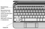
In the bios, they hide under the names Cool " n " quiet, as well as C 1 E- they should be put out of position.
Photo energo-enabled
1.1. Bus overclocking technique
1. We go into the bios. We reset everything to default with the F2 or F5 or F8 or F9 key, etc. - Each motherboard is different. We save and exit.
2. We go into the bios.
We look at the part that is responsible for overclocking. In my case, everything looks like this:


We remember (beginners can also write down on a piece of paper) these numbers:
Current CPU Speed- current processor frequency.
Target CPU Speed- the frequency of the processor, which we set at the moment.
Current Memory Frequency- current frequency of RAM.
Current NB Frequency- the current frequency of the memory controller built into the processor and the cache memory of the third level (L3), it is also called CPU / NB. It is this frequency that decides at what speed the processor and RAM will "talk". The CPU/NB frequency can also be overclocked - and the increase from it is more noticeable than with a similar overclocking of the processor itself.
Current HT Link Speed- current frequency of the Hyper Transport bus (hereinafter - HT), which connects the northbridge and the processor. Although initially the real frequencies of CPU/NB and HT are equal, the effective speed (more precisely, the bandwidth) of the HT bus is so high (5.2 billion messages per second) that it doesn't even need overclocking.
In addition, its architecture is such that the HT frequency cannot be higher than the CPU/NB frequency. Therefore, only the CPU / NB should be overclocked, and the HT frequency should be left at its nominal value - 2000 MHz.
3. Now we start fixing the necessary parameters:

AI Overclock Tuner- from set to, that is, we transfer automatic overclocking to manual mode. This allows us to control the bus frequency.
CPU Ratio- we translate the multiplier of the processor from to , using the "plus" and "minus" keys. That is, we fix / fix the nominal multiplier - so that the BIOS does not “accidentally” change it automatically.
CPU Bus Frequency- we set the proca bus from - these are nominal 200 MHz.
PCI - E Frequency- PCI-E bus fixed at nominal 100 MHz.
Memory Frequency- the memory frequency is fixed on native 1333 MHz.
CPU / NB Frequency- the frequency is fixed on native 2000 MHz.
HT Link Speed- also fixed on native 2000 MHz.
CPU Spread Spectrum- set to - disable the feature that reduces EMP from the computer, this gives stability during overclocking. Why - read.

PCI - E Spread Spectrum- also put in - purely for reinsurance.
EPU power Saving mode- Energy-saving technology from Asus, which allows you to regulate the power consumption of motherboard components. As I wrote above - in a state of overclocking - all sorts of "energy savers" are evil, so we put it in .
Then there are voltage adjustments (subsection digi + VRM) - here we touch only those that are directly responsible for controlling the processor voltage. This:
CPU Voltage Frequency- translate from position set to - for manual voltage adjustment.

CPU & NB Voltage-translate from to - this allows you to manually directly specify the voltage of the processor. In the mode, the processor voltage is indicated by an offset (plus or minus) relative to rated voltage, which is, as the photo clearly shows - 1.368 V. And such an adjustment is of no use to us - it only confuses beginners more.
CPU Manual Voltage- using the "plus" and "minus" keys, fix the rated voltage - 1.368750 V.
This is how we fixed all the nominal voltages of the computer so that no bios automation could change them. Save bios and reboot.
4. Let's go to the OS.
Download and install the most fresh/latest versions programs:
- CPU - Z- to monitor the state of the processor - the multiplier and the final frequency of the processor, as well as its voltage.
- Core Temp- to monitor the temperature of the processor.
- Lin X- a program for creating maximum load on the processor. This program loads the processor with a system of linear algebraic equations, which load all the processor cores evenly to the eyeballs, since they are well parallelized.
For more or less accurate testing of processor stability on the specified bundle [frequency CPU - voltage CPU ] in principle, it is enough to specify 10 runs in the LinX program settings, using more than 50% of the total RAM. With 8 GB of memory, I recommend using 5 GB of memory.
In the picture below, I have indicated, as you can see, 10 runs using 1 GB of memory (1024 MiB). MiB (mebibyte) is the same Russian megabyte - 2 20, but according to the IEC standard. So there is no difference and you should not be afraid.
5. Open CPU-Z, Core Temp and Linx. We put their windows side by side so that they do not interfere with each other.
We start LinX in 10 runs.

After we reboot.
6. We go into the bios.
And increase CPU Bus Frequency c 200 to 210 MHz.

As you can see the parameter Target CPU Speed simultaneously increases to 3570 MHz. Those. we overclocked the CPU to this frequency from the nominal 3400 MHz.
Memory - 1399 MHz.
CPU / NB and HT - 2100 MHz each.
under the word " not much different" means that they fall within (+/-) 100 MHz from the nominal frequencies.
7. Let's go to the OS.
We start LinX in 10 runs.
To make a photo!!!
And we look at how much the maximum warms up the processor. We remember the performance of the processor in Gflops.
After we reboot.
8. We go into the bios.
And increase CPU Bus Frequency c 210 to 220 MHz.

As you can see the parameter Target CPU Speed simultaneously increases to 3740 MHz. Those. we overclocked the CPU to this frequency from the nominal 3400 MHz.
Memory became 1466 MHz.
CPU / NB and HT steel at 2200 MHz.
Therefore, so that the memory frequencies do not "raise" too high relative to the nominal 1333 MHz, we reduce it as in the pictures below (this can also be done with the plus and minus keys) to 1172 MHz.
We start LinX in 10 runs.

And we look at how much the maximum warms up the processor. We remember the performance of the processor in Gflops.
After we reboot.
10. We go into the bios.
And increase CPU Bus Frequency c 220 to 230 MHz.

As you can see the parameter Target CPU Speed simultaneously increases to 3910 MHz. Those. we overclocked the CPU to this frequency from the nominal 3400 MHz.
At the same time, the memory, CPU/NB and HT frequencies also increase.
Memory - 1225 MHz.
CPU / NB and HT - 2070 MHz each.
The frequencies of the memory, CPU/NB and HT do not differ much from the nominal ones - that's why we don't touch them.
Save and reload.
11. Let's go to the OS.
We start LinX in 10 runs.

And we look at how much the maximum warms up the processor. We remember the performance of the processor in Gflops.
After we reboot.
12. We go into the bios.
And increase CPU Bus Frequency c 230 to 240 MHz.

As you can see the parameter Target CPU Speed simultaneously increases to 4080 MHz. Those. we overclocked the CPU to this frequency from the nominal 3400 MHz.
But - at the same time, the frequencies of memory, CPU / NB and HT are also growing.
Memory became 1279 MHz. We do not touch it, since it enters the interval 1333 MHz (+/-) 100 MHz.
CPU / NB and HT steel at 2160 MHz.
We reduce the CPU / NB and HT frequencies to an acceptable 1920 MHz. Let me remind you that the nominal frequencies of CPU/NB and HT are 2000 MHz.


Thus, when overclocking via the bus, we constantly have to make sure that the CPU / NB and HT memory frequencies do not deviate too far from the nominal ones. Why - I will explain later.
Save and reload.
13. Let's go to the OS.
Oops! Suddenly there is a blue screen of death - this means one thing - for a given processor frequency ( 4080 MHz) exposed processor voltage in the BIOS (according to clause 3) - 1.368750 V- lacks.

We press the button reset and reboot.
14. We go into the bios.
According to item 3, we find the parameter CPU Manual Voltage- and again using the "plus" and "minus" keys we increase and fix the voltage - 1.381250 V.

Save and reload.
Continued tomorrow.
P35 Platinum motherboard BIOS menu. All performance-related functions, except for peripherals (peripherals), system time (time), power management (power management), are in the “Cell Menu”. Users who wish to adjust the frequency of the processor, memory, or other devices (such as graphics card bus and southbridge) can use this menu.
Remember that if you are not familiar with the BIOS settings, it is recommended that you complete all the settings quickly by completing the “Load Optimized Defaults” item, which will ensure the normal operation of the system. Before overclocking, we recommend users to complete this item first, and then make fine adjustments.

Cell Menu Board P35 Platinum
All settings related to overclocking are located in the "Cell Menu" section, which includes:- Intel EIST
- Adjust CPU FSB Frequency
- CPU Ratio CMOS Setting
- Advanced DRAM Configuration (special DRAM configuration)
- FSB/Memory Ratio
- PCIEx4 Speed Controller (PCIEx4 speed control)
- Adjust PCIE Frequency
- Auto Disable DIMM/PCI Frequency
- CPU Voltage (CPU supply voltage)
- Memory Voltage
- VTT FSB Voltage (voltage VTT FSB)
- NB Voltage (Northbridge voltage)
- SB I/O Power (Southbridge I/O Power)
- SB Core Power (Southbridge core power)
- Spread Spectrum (Clock Spectrum Limitation)
The user interface of the Cell Menu is very simple. Related functions are grouped in it. Users can match parameter values and make settings step by step.
Before overclocking, please set the functions“ D.O.T. control” and “Intel EIST” to “Disabled” state (Default is Enabled). These settings allow you to set custom values for the processor supply voltage and system bus frequency. After disabling these functions, the option “ CPU Ratio CMOS Setting” .


1. CPU frequency: After loading the optimal settings, this option will automatically show the CPU frequency. For example, for an Intel Core 2 Duo E6850 processor, it will show “333 (MHz)”. The frequency setting can be done with the numeric keys or the “Page Up” and “Page Down” keys. When adjusting, the value displayed in gray font “Adjusted CPU Frequency” will change according to the set frequency.

2. CPU frequency multiplier: Depending on the nominal frequency of the processor, for example, 1333MHz, 1066MHz and 800MHz, the range of multiplier values will be different.

3. Special DRAM configuration: This option is for setting the duration of the memory delay. The smaller its value, the higher the speed of operation. However, the limit of its increase depends on the quality of the memory modules.
Advice: If you are using commercially available overclockable memory modules, we recommend that you go to "Cell Menu" > Advanced DRAM Configuration > Configure DRAM Timing by SPD, set this option to Disable, then you will see 9 additional custom options to improve memory performance.

4. FSB/Memory Ratio (Frequency Ratio of FSB and Memory) : This setting determines the relationship between the FSB and memory frequencies. When set to ”Auto”, the memory frequency will be equal to the processor frequency. When setting a custom value, please follow the 1:1.25 rule. For example, a processor with a frequency of 1333MHz and DDR2-800 memory. Then 1333MHz / 4 x 1.25 x 2 = 833MHz and the DDR2 frequency will be 833MHz.

5. Adjust PCIE Frequency : Typically, PCI Express bus clock speed has no direct relationship to overclocking; however, tweaking it can also help overclocking. (The default value is 100. It is not recommended to set this value to more than 120 as it may damage the graphics card.)
6. CPU Voltage (CPU supply voltage): This item plays a crucial role in overclocking, however, due to the complexity of the relationships, it is not so easy to find the best setting for it. We recommend that users perform this setting with caution, as an incorrect value may cause processor failure. According to our experience, when using a good fan, it is not necessary to set this value to the limit value. For example, for Core 2 Duo E6850, it is recommended to set the supply voltage to 1.45~1.5V.
7. Memory Voltage (memory supply voltage): Since the memory is controlled by the Northbridge, the memory supply voltage should be increased at the same time as the supply voltage of the main nodes. Of course, the limit of this increase depends on the quality of the memory modules.
8. VTT FSB Voltage (supply voltage VTT FSB): To ensure that all major components of the system have close operating voltages, the VTT FSB supply voltage must also be increased. This value should not be too high, so as not to cause undesirable effects.
9. NB Voltage (Northbridge supply voltage): The Northbridge plays the most important role in overclocking. Maintaining the stability of the processor, memory and graphics card can be achieved by increasing this voltage. We recommend that users fine-tune this setting.
10. SB I/O Power (South Bridge I/O Power): The southbridge controls the connection of peripherals and expansion cards, which play a more important role on new platforms from Intel. The default voltage value for the ICH9R is 1.5V, which determines the I/O voltage setting for peripheral devices. We recommend increasing the voltage to 1.7~1.8V, which will increase the stability of the connection between the North and South bridges, as well as help overclocking.
11. SB Core Power (South Bridge Core Voltage): Previously, during overclocking, the Southbridge was ignored, however, as the supply voltage increases, it improves performance.
It should be remembered that MSI highlights the values of the settings in different colors: gray indicates the default settings, white indicates safe values, dangerous ones are highlighted in red.

Adviсe: MSI Warning: Check fan speed frequently. Good cooling plays a decisive role in overclocking.