- Be kind, explain why I have after reinstalling Windows 7, RealTek sound card, installed the sound driver from the motherboard CD, the Realtek manager is installed and there is sound in the operating system. But I connect the headphones to the front panel and there is no sound, before reinstalling the operating system the sound was. Georgy.
- Letter number 2 Answer such a question, I recently reset the configuration of my BIOS to default (by default) and now I have front sound panel does not workThe network says it is necessary to install the RealTek manager, but it never happened to me, it means that something else is probably in the BIOS settings. Anton.
- Letter number 3 why I have no sound in headphones in Windows 7 When connecting them to the front panel? Realtek sound card. On one of the forums on the Internet, I was advised to enter the playback devices and simply turn on the headphones, but I can't work, because they are written High Definition Audio supporter is not connected And if you click on them with the right mouse, then this menu will come out and as you can see them can be turned off, and not turn on. I also read on one site that you need to go through-\u003e Control Panel-\u003e Sound - on tabs Reproduction Or write to select the correct device and click the default, but also does not help. Kristina.
Front sound panel does not work
This article Friends will suit both the Windows 7, Windows 8 operating system and for Windows XP, if there is a difference, I will definitely show you where.The answer to the first question. Let's figure out with a non-working front sound panel, firstly in most cases, you need to install Realtek Manager. If it is installed, it means there should be its icon on the taskbar
if it is not there, go to the launch - Control Panel - Realtek Manager. In Windows 7.


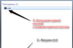
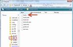
if there is also absent, try to find it in the folder
When you run the Realtek Manager in Windows 7, press the speakers button, then click the mouse on the yellow daddy in the upper right corner and window appears Connector parameters,

we see a warning If the definition of the front panel nockets does not work properly, check this check box. Disable the definition of the front panel nockets., put a tick on this point and click OK.

After these actions, the front sound panel should earn.
In the Windows XP operating system, the REALTEK manager looks a little different, but the essence of the same. Press the left mouse on the button with a wrench

and in the window that appears, mark the checkbox Disable the front panel nocket definition and ok

the front sound panel should earn.
We can also click on the button Additional settings Devices in this window and adjust everything as we need, for example, to note the item -. This means that when you connect to the front sound panel of headphones, the sound speakers connected to the motherboard are immediately disconnected.
In Windows 7.


Now I am responsible for the second letter. It happens friends that the drivers on the sound card are installed and the sound is present in the system, but the front sound panel does not work, the reasons for this are usually two.
First: the front sound panel works for you on a slightly outdated AC "97 and the cable running from it is connected to the connector on the AAFP ANALOG AUDIO FRONT PANEL ( designed specifically for connecting audio front panel connections).
- Note: AC'97- Outdated standard audio codecs, veteran can be said, Intel has developed in 1997, applied in motherboards, as well as cases with the front panel audio panel. But the sound subsystem built into your motherboard works on a newer standard-high definition Audio or HD Audio, because of this, the front sound panel may not work. Intel High Definition Audio- is a relatively new Specification for audio codecs, developed by Intel in 2004, characterized by the improved digital sound quality, an increase in channels, a higher frequency of transmission compared to AC "97.
Reboot and go to the BIOS. We go to the ADVANCED item, then Onboard Devices Configuration

and finally, the option is responsible for the front audio panel Front Panel Type, it can still be called:
Front Panel Support Type, HIGH DEFINITION FRONT PANEL AUDIO, Legacy Front Panel Audio, is located by default in the HD Audio position,

rearrange it to position, save the changed settings and leave the BIOS. After rebooting, the front sound panel should work.


Just if your front panel works in HD Audio, then in BIOS you need to switch it from the position to the HD Audio. In any case, experiment.
Friends if you connect the front audio panel AC "97 to the AAFP connector on the High Definition Audio Specification Motherboard,

That all you will work fine, only in some cases, when connecting headphones to the front sound panel, in the audio columns will not turn off the soundEven if you disconnect in the Realtek Manager settings Disable the sound of the rear output device when the front output device is connected to the headphone.
All this due to the fact that the manufacturers of the front sound panel use the simplified cable splitting circuit and the front panel outputs of the AC97.
Output here Two, the first to turn it (not so simple), the second to buy a new case, with the support of the front sound panel HD Audio, and in case of purchasing a new computer, refine all from the seller, do not be surprised if you buy a new system unit in a non-specialized supermarket, Faced with the complete ignorance of consultants in this matter.
Well, the latter that you need to check if the front sound panel does not work, it is connected to a motherboard with a cable, sometimes it can simply forget to connect it when assembling a computer, as on this virginity.
The front sound panel Cable AC "97 forgot to connect to the AAFP ANALOG AUDIO FRONT PANEL connector on the motherboard.

Well, Christine from the third letter, we set a new version of the driver from the official site and set up the front audio panel in the RealTek Manager, everything is written in our article. How to install a driver for sound Detailed.
In this article, you will learn how to connect the power switch, reset and LEDs, as well as audio and USB ports to the motherboard. Before trying to connect them, it is very important to know the place, and the polarity of the connection. To do this, it is necessary to find schemes in the motherboard manual, which will prompt you exactly where every set of contacts on the motherboard is located or use the information in this article.
Connecting indicators and power buttons
The computer case has buttons for power management that are connected to the motherboard, and LEDs to designate the motherboard. You must connect these buttons and indicators to the motherboard using wires from the front of the housing shown in Figure No. 1, in the connector on the motherboard (Fig. No. 2). The inscription on the motherboard near the panel connector shows the connection site of each wire and the polarity of each of them however, the inscriptions with the designations are not always present on the motherboard.
Find the front panel connectors in the computer case (see Fig. 1). Next, we find a connector on the motherboard usually it is at the bottom of the motherboard, and signed by the inscription Panel1 or JFP1, it may be in different design (see Fig. 2.0, 2.1).
Fig. №1. Front panel connectors.  Figure No. 2.0. Front panel connector on motherboard.
  Fig. No. 2.1. Front panel connector on motherboard.
A group of system cables shown in Picture No. 1 have two wires that have a color marking. Black or White Wire This Earth (GND), and wires of other colors (red, blue, green, orange) is meal. Connection is carried out from left to right, when connected all the plus contacts will always be left in addition to the RESET button, however, the polarity of the buttons of the buttons as the buttons press the contacts are closed.
Just install these wires to the connector with the same name on the motherboard, observing the polarity of the LEDs.
 Fig. No. 2.2. The polarity of the front panel wires.
 The abbreviated names for them are listed below, which will be recorded on the connectors themselves.
PWR-SW, PW SW, PW \u003d Power button (POWER SWITCH) (Polarity is not required). Control Power Button, which allows you to turn on and off the computer.
PWR-LED, P-LED, MSG \u003d Power LED (Polarity Required). The indicator shows when the computer is turned on or is in standby mode.
RES-SW, R-SW, RES \u003d Reset Switch (Reset Switch) (no polarity required). Reset button to restart the computer.
HDD-LED, HD\u003d Hard Disk Drive LED LED (polarity required). This indicator flashes when recording and reading information from a hard disk.
SPK, SPKR, SPEAK \u003d Internal speaker (SPEAKER) (Polarity requires) used to sound sound signals that you hear from the computer when loading.
 Figure 3. Pickup Contacts of the Front Panel on the motherboard
 Connecting the front panel USB to the motherboard
First, we find the USB connector on the motherboard, it is usually located at the bottom of the motherboard and signed an F_USB or USB inscription. Also on each wired connector (Fig. No. 4.0), you can read its value that can be + 5V (or VCC or POWER), D +, D - and GND.
 Figure No. 4.0. USB polarity.
  Figure No. 4.1. Connecting USB 2.0 front panel to the motherboard.
  Figure No. 4.2. Connecting USB 3.0 front panel to the motherboard.
  Figure No. 4.3. Connecting USB 2.0 to the motherboard.
 Connecting the audio front panel to the motherboard
To use these connectors, your motherboard must have a built-in audio card (in other words, built-in sound). However, the installation is not as simple as it seems, and in today's column we will explain how to do it.
At the end of each wire there is a small black connector, and in this connector we can read the wire function. You will find the following wires: MIC IN (or MIC DATA), RET L, RET R, L OUT (or EAR L), R OUT (or EAR R) and two GND (or Ground). If you look carefully, you will see the RET L and L OUT wires are connected to each other, the same thing happens between the wires RET R and R OUT.
 Figure No. 5.0. Connect audio to motherboard.
 You must find the place of installation of such wires in your motherboard. This place is indicated as Audio, External Audio, EXT Audio, Front Audio, F Audio, HD Audio or something like that. This connector consists of a 9-pin connector, and there are two jumpers that establish a connection of some of these contacts. The exact position of this connector varies depending on the model of the motherboard.
 Figure No. 5.1. View of the audio plug on the motherboard.
 To install wires, the first step is to understand the numbering system of the pins of the motherboard connector. There are nine contacts in the connector, but the connector is considered to be 10-pin, because one of the contacts was removed (contact 8). The jumpers connect the contacts 5 and 6 and 9 and 10. Since there is a space without a pin (contact 8), it is easy to detect the numbering of other contacts.
 Figure No. 5.2. Cutting audio on the motherboard.
 Remove jumper. Wiring must be connected as follows: MIC IN TO PIN 1; GND - contacts 2 and 3; R to output 5; RET R for output 6; L Conclusion to contact 9, and RET L - on contact 10.
Good day, dear readers. As you understand from the header, we will talk about connecting the front panel and the connectors of the mat. Payment to the body or vice versa.
This article, which represents a small addition to the once written material about the assembly of a computer under the same name "We collect the computer with your own hands" or "what is that in the computer, part 2".
It will be about a small missed, but important element, - connecting the connectors (all sorts of the buttons, light bulbs, etc.) of the front panel.
Go.
Connecting the front panel - Instructions for connecting
On the front panel of the system unit, the power and manual reboot buttons are usually located. They also need to connect to. Connection cables are usually made in the form of pins (what is pins are above).
They look like this (clickable):

Power SW - Cable Turning Button; Power LED + - - power cables (light bulbs); HDD LED - load indicator cable (the same light bulb that usually flashes); Reset SW - Reboot Button Cable.
The correct connection of the front panel connection is also important, since without this, the computer will simply not turn on.
Each motherboard is the so-called FRONT PANEL contact unit or abbreviated F-Panel. It is usually located in the lower right corner of the board, but there are exceptions. This is how about it looks:

Connecting the front panel connection and its pins is carried out manually and for this in the accompanying documents to the motherboard necessarily there are tips.

If there are documents, you are not difficult to connect. If not, then on the motherboard around or next to the F-Panel block are tips. If you are lucky repeatedly, then in a set with a mat. Pay there is such an adapter:

In which you just stick, as shown above, the connectors themselves, and then this adapter in the mat. Pay and everything turns out quickly and simply. But luck is so far away, and you probably got here because you are trying to connect everything for an already former (and not new) motherboard.
What else is worth knowing
In addition, on the front panel of the system unit, there are sometimes USB interface connectors (usually their pair of pieces) and headphone / columns and microphone ports. It looks like this:

Cables for connecting these external USB ports, inside the system unit look like this:

They are connected to the blocks of pins on the motherboard, which are called F- USB1 and F-USB2, respectively (look in color and location may not quite as in the screenshot below, but in the form and quantity \\ location of the pins is all the same):

Approximately similar to the ports of connecting external audio inputs, it is distinguished by the position \\ number of pins, so that the front panel connection in this regard is not a completely complex task.
Connect them simply (in other blocks of pins they simply do not fit). But for them in the accompanying documents for the mat board, there are also tips:

Actually, everything and nothing complicated in it.
What should I do if the documentation for the mat is not preserved
Or take a magnifying glass and carefully read the connector mentioned above for connecting to the computer's motherboard:

Usually it is somehow somehow, but it is symbolic signed, times so from the second or the third you can guess what everything is going on there and connect everything correctly. Wires are connected, as a rule, inscription:

Occasionally, the second row (far) looks inscriptions in the other side, but this is rare enough. One way or another, as I wrote above, not from the first, so from the second time - guess :)
If you can not consider anything (you never know a little vision or the inscriptions are poorly spelled out), then you open the site of the manufacturer Mat. payments and there are looking for the section "Support" (or type of one), where you can usually download the instructions from the mat. Payment, where always described Connection.

If you could not find on the site manufacturer, you can find on the Internet on the request "card name" + word MANUAL, with minimal knowledge of English, you will definitely find it, and there it is already a matter to open, look and connect.
Afterword
If there are any questions or additions, write in the comments or using. I will be glad to help and just listen to you.
PS: The figures presented in the figures are shown exclusively for examples and familiarization. No advertising.
PS2: The article is written by a person who lives in the network under Nick (a friend and assistant project). For what he is so many thanks.
Hello, guests and frequent visitors of my blog;).
Did you decide to assemble your computer yourself? Or, on the contrary, first disassembled, because the ports did not work ahead of the system unit, and now you want to return everything back? You got, where you need. Here you will learn how to connect the front panel to the motherboard.
I do not advise you to skip this article in the confidence that you and without it do it right. Of course, this does not apply to professionals, although in this case the error is not uncommon.
Why?
The fact is that the process not only seems simple - he is also. However, one important nuance assumes - the assembly sequence. If it is not respected, some ports may not work.

Also those who collect the systemist for the first time can get confused in the abundance of wires. Not literally, although who knows. So I recommend that you not only read my publication to the end, but also armed with the instructions for your motherboard. The location of the ports on all models is usually equally equally, but sometimes there is a marking of the connectors, which can mislead you.

No manual in my arms? Find it on the Internet. If it did not come out with this, then carefully follow the actions described in this article, and I think you will succeed.
Guide to the assembly
As mentioned, it is necessary to collect consistently, so I deal my manual on several blocks. So you definitely do not confuse.
Indicators and buttons
The light bulbs on and restarting the computer, as well as the node with the buttons are connected first. These elements are on one plume, from which separate connectors of different colors come out. They can also be called differently, depending on the model of your iron. But the designations are usually similar, so you can easily figure out what.

What contacts are dealing with?
- Power SW (PWRBTN) - belongs to the start button of the computer;
- D.D.LED (+ HDLED) - Winchester indicator, which constantly flashes;
- RESTART SW (RESET) - is responsible for the reboot button;
- Power LED + - - Turn button light bulb.
All these wiring are connected to one port located in the lower corner of the motherboard on the right. It can be written "F_PANEL" or "PANEL". Also usually tip the prompts that to insert. But just in case I make a photo.

By the way, in nature there are comfortable extension glands, in case, if you suddenly do not have enough length of your wiring.
You will also need to connect a small speaker - SPEAKER, which beeps when the PC is turned on or with system or hardware errors. Typically, a separate port is given to 4 pins for him, but it happens that it is inserted along with the above connectors.
USB
Now go to the USB connection on the front panel. His contacts are similar to the previous ones. But the situation is simplified by the fact that they are connected in one fork and do not need to insert each separately.
The place for them is assigned at the bottom of the board and signed as F_USB1, 2. Ports for these connectors may be several. It does not matter what exactly you connect them. The only nuance: Plugs yusb 3.0 and 2.0, differ slightly. The third revision is sewn and with a large number of contacts.

Audio connectors
It's time to connect the sound. The cable is similar to Yusb-shny, that is, the connectors are also combined into one fork. The port is usually located next to USB and is indicated as AAFP, AUDIO, A_AUDIO.

At your disposal will be the "HD Audio" or "AU 97" cable (if you do not have a discrete sound card). If after it is connected, the headphone or microphone connector does not work, check the front audio panel settings in the BIOS. It happens that the system is the "AC97" driver, and "HD Audio" is installed in the BIOS. Place the correct parameters.

In principle, everything, nothing here is not enough :)
Subscribe to updates and tell someone in social networks, how to connect the front panel to the motherboard. By throwing a link to this article.
I will be very happy to see you as often as possible on the blog pages.
On the front panel of the system unit are the buttons that are required to turn on / off / restart PCs, hard drives, light indicators and a drive, if the last two are provided with the design. The process of connecting to the motherboard front of the system unit is a mandatory procedure.
To begin with, learn the appearance of each free connector on the system board, as well as cables to connect the front panel components. When connected, it is important to comply with a certain order, because If you connect one or another item in a non-order, then it can work incorrectly, not to work at all or disrupt the operation of the entire system.
Therefore, it is important to study the location of all elements in advance. It will be very good if there is an instruction or other paper to the maternal card, which explains the scene of connecting certain components to the board. Even if the documentation for the motherboard on another, different from the Russian language, do not throw it out.
Remember the location and the name of all elements is easy, because They have a certain appearance and marked. It should be remembered that the instruction given in the article is common, so the location of some components on your maternal card may be a little different.
Stage 1: Connect buttons and indicators
This stage is vital for the computer, therefore it is required to be performed first. Before starting work, it is recommended to turn off the computer from the network to avoid a sudden voltage jump.
On the motherboard highlighted a special unit, which is intended only for alignment of wires of indicators and buttons. He is called "Front Panel", "Panel" or F-Panel. On all motherboards, it is signed and located at the bottom, closer to the alleged location of the front panel.
Consider connecting wires in more detail:
- Red wire - Designed to connect the Turn on / off button;
- The yellow wire is connected to the computer's reset button;
- The blue cable is responsible for one of the indicators of the system status, which is usually lit when the PC is rebooting (there are no such cases on some models);
- Green cable is designed to connect a motherboard with a computer power indicator.
- White cable is needed to connect power.

Sometimes red and yellow wires "change" with their functions, which can be confused, so it is desirable to study the instructions before starting work.
Places to connect each wire are usually designated by the appropriate color or have a special identifier that is prescribed either on the cable itself or in the instructions. If you do not know where to connect one or another wire, connect it "at random", because Then you can still reconnect.

To check the correctness of the connection of cables, connect the computer to the network and try to enable using the button on the housing. If the computer turned on and all indicators are burning - it means that you all connected everything. If not, then turn off the computer again and try to change the wires in some places, you may just install the cable not on that connector.
Stage 2: Connecting the remaining components
At this stage, you must connect the connector for USB and the system block speaker. The design of some enclosures does not provide data to the elements on the front panel, so if you did not find any outputs for USB on the case, you can skip this step.
Places to connect connectors are not far from the slot to connect buttons and indicators. They also wear certain names - F_USB1. (the most common option). It should be borne in mind that these places can be more than one on the motherboard, but you can connect to anyone. Cables have the appropriate signatures - USB and HD Audio..

Connecting the USB-input Wire Looks like this: Take the Cable with the inscription "USB" or "F_USB" And connect it to one of the blue connections on the motherboard. If you have a USB 3.0 version, you will have to read the instructions, because In this case, you will have to connect the cable only to one of the connectors, otherwise the computer will incorrectly work with USB drives.

Similarly, you need to connect the sound cable HD Audio.. The connector under it looks almost the same as under USB outputs, but has another coloring and is called either AAFP.either AC90.. It is usually located next to the USB connection site. On the motherboard he is only one.
Connect the front panel elements to the motherboard is easy. If you allow something error, then this can be fixed at any time. However, if you do not fix it, the computer can work incorrectly.