What are blocks in AutoCAD? To answer this question, we will immediately give a definition. A block is a set of primitives (segments, polylines, circles, etc.) and individual elements that are grouped into a single solid object.
The use of blocks in AutoCAD greatly facilitates their reuse both within one drawing and in other projects.
Blocks are either static or dynamic. The dynamism of a block can consist, for example, in changing its size, shape, scale, etc. Looking ahead, I would like to note that dynamic blocks in AutoCAD allow you to solve a wider range of tasks than static ones. On fig. Figure 1 shows an example of AutoCAD blocks from the Cars collection.
Fig.1. Using blocks in AutoCAD on the example of cars.
When it comes to blocks you need to clearly understand what a block entry in AutoCAD is, and what a definition is.
Definition of the AutoCAD block.
After you have drawn the graphic elements, you need to convert them to a block. To do this, select the "Create Block" command, and then set the name, base point, and indicate the drawing elements themselves (read more about creating blocks in AutoCAD). An AutoCAD block definition is information about the name, base point, and geometric entities included in the block.
Block entry in AutoCAD.
Blocks for AutoCAD are a very important feature!
There are very important features of AutoCAD blocks. To understand them, consider an example.
Let's imagine a situation: with the help of a block, an element was created, the occurrence of which in the drawing will be repeated a very large number of times (for example, windows on the facade of a multi-storey building). After the completion of the project, at the request of the customer, it became necessary to change the appearance of this element.

Fig.2. Application of blocks in AutoCAD on the example of windows.
So, the biggest advantage of blocks is that it is enough to edit only one block definition (ie its main description), and all other occurrences will automatically change. Otherwise, you would have to edit each object separately, or make changes for one element, copy it and paste it again.
Thus, it is possible to collectively control the properties of the blocks. You need to understand that blocks for AutoCAD are just graphic links to the data area of the file, where the block description itself lies. That is why the use of blocks in AutoCAD significantly reduces the file size.
Summarize. Now you know what blocks are for in AutoCAD. The main thing is that you realize the importance of their use, because. it saves computer resources, your time and nerves!
Changing Data in Block Attributes
Editing Block Attribute Definitions
Splitting a Block into Components (Explosion)
Editing block definitions
Bottom of page
Procedure
Quick Reference
Changes to block definitions in the current drawing affect both block references already created in the drawing and future ones.
The user can override block definitions in the current drawing. Changes to block definitions in the current drawing affect both block references already created in the drawing and future ones, as well as any attributes associated with the blocks.
There are two ways to edit a block definition:
Change the definition of a block in the current drawing.
Change the block definition in the source file and re-insert it into the current drawing.
The choice of method depends on whether you want to make changes only to the current drawing, or you also need to change the original block file.
Change the definition of a block in the current drawing
To change a block definition, follow all the steps for creating a new block, but the name you enter must match the name of the block definition you are editing. When overridden, any existing block occurrences in the drawing are immediately updated.
To make things easier, you can insert a block and explode it, and then use the resulting objects to create a new block definition.
Block update when source file changes
Changing the source drawing of a block does not have an immediate effect on the current drawing where the block is inserted. To update a block in the current drawing pasted from a source file, use the INSERT command.
Updating a Block When a Component Library Changes
When you insert a block definition of the same name using the Design Center, the block already in the drawing is not deleted. To update a block definition from a library, you can use the WBLOCK command, which creates a separate block file from the Content Center. The INSERT command is then used to overwrite the block definition in the drawing where the block is used.
Note When using the INSERT command, the descriptions for the blocks are reset. Text descriptions for blocks displayed in the "Block Definition" dialog box can be copied between block descriptions via the clipboard.
Editing Block Descriptions
To change the descriptions for the blocks displayed in the Control Center, use the BLOCK command. In addition, you can also add descriptions to existing blocks in the Block Definition dialog box.
Redefining Block Attributes
Attributes are associated with a block when it is created or redefined. Required attributes are included in the block during feature selection for the block. Redefining attributes in a block description has the following effects on already created block occurrences:
Permanent attributes that have fixed values (constants) are lost or replaced by new attributes.
Variable attributes remain unchanged even if there are no attributes at all in the new block definition.
New attributes do not appear in existing block occurrences.
see also
Attaching Data to Blocks (Block Attributes)
Changing Dynamic Block Definitions
Procedure
To change the definition of an existing block
Select an editable block.
Right-click on the block and select "Properties" from the context menu.
In the "Properties" window, select and change the values X and Y base point coordinates, scale factors, rotation angle and other parameters.
To update a block when the source file changes
To edit the block description
Changing Data in Block Attributes
The user can edit attribute values that are attached to the block and inserted into the drawing.
There are several ways to edit attribute values associated with a block:
Double click on the block to open the "Advanced Attribute Editor"
Hold down the Ctrl key and double-click on the block to open the context editor
Open the Properties palette and select the block
You can also change the position of attributes in a block using grips. You can also use grips to change the text width when working with multi-line attributes.
Note If you hold down the CTRL key and double-click on an attribute that contains a hyperlink, the corresponding web page will open. To edit an attribute, use one of the following methods.
Procedure
To edit attributes
Editing Block Attribute Definitions
You can edit the values and other properties of attributes already associated with blocks inserted in the drawing.
Modifying block definition attributes is done using the Block Attribute Manager. For example, in it you can edit:
Properties that determine the order in which values are assigned to attributes and are responsible for displaying or suppressing the display of values in the graphics area
Properties that control the display of attribute text in a drawing
Properties that define the layer, color, weight, and linetype for attribute output
By default, changing attributes affects all existing block references in the current drawing.
Changing the attribute properties of existing block references does not affect the values associated with those blocks. For example, if a block attribute is named "Cost" with a value of 19.99, then changing the attribute name to "Unit Cost" will keep the value the same.
Updating attributes with the same name can produce unpredictable results. You can use the Block Attribute Manager to identify duplicate names and change them.
To update block references in the graphics area after changing their permanent and nested block attributes, use the REGEN command.
Changing the Order of Attribute Value Prompts
When you create a block definition, the attribute selection order determines the order in which you are prompted for their values when you insert the block. You can change this order using the Block Attribute Manager.
Removing Block Attributes
In the current drawing, the user can remove attributes from block definitions as well as from all existing block references. Attributes removed from block references do not disappear from the drawing area until the drawing is regenerated by the user using the REGEN command.
You cannot remove all attributes from a block in this way; at least one attribute in the block must remain. If you need to remove all attributes, you must redefine the block.
Update block references
After making changes to block definitions, the user can update the block references in the current drawing. When editing attribute properties in block definitions using the Block Attribute Manager, existing block references in the drawing are not automatically updated. Once the changes are complete, the user can apply the changes to all blocks in the current drawing.
You can also use ATROUPDATE to update attribute properties on block references to match block definitions, or to update a block instance after redefining a block attribute using the BLOCK, -BLOCK, or BLOCKRED commands.
Updating attribute properties on block references has no effect on the values of those attributes.
Editing Attributes in Block References
You can select an attribute in a block reference and use the Properties palette to modify its properties, or you can use the Advanced Attribute Editor to modify all attributes in the selected block reference.
Procedure
To edit attributes in block descriptions
To enable or disable applying changes to existing block references
To apply your changes to existing block references, select the Apply to existing references check box.
To apply your changes only to new block occurrences, clear the Apply to existing occurrences check box.
Click OK.
To find duplicate block attribute names
To change the order of attribute value prompts
For the selected block, a list of attributes is displayed in the order in which requests for their values were made.
To change the position of an attribute in the list, select it and press the "Up" button to move up the list or the "Down" button to move down.
Note For constant attributes (Mode=C) that define constants, these buttons are not available.
To remove an attribute from a block definition and from all occurrences of blocks
Attributes removed from existing block instances do not disappear from the graphics area until the drawing is regenerated by the user using the REGEN command.
To update changed attributes in existing block references
To update the attributes in the entries associated with the selected block description
Enter name, then enter the name of the block whose entries you want to update.
Enter ? to get a list of blocks, then type name and block name.
Press Enter and then point to the block in the drawing area using the pointing device.
If you enter the name of a block that does not exist, or if you select a block that does not have attributes, an error message appears.
Another way
Click "Apply" to save the changes. The Block Attribute Editor remains open.
When you click the Cancel button to exit the Block Attribute Editor, any changes saved by clicking the Apply button remain in effect.
Click "OK" to save your changes and exit the Block Attribute Editor.
Click "Select block" to edit the attributes of another block. If the changes made to the current block have not been saved, a save prompt is issued before starting to select a new block.
Splitting a Block into Components (Exploding)
In order to be able to edit individual objects included in the block, it is necessary to split it into separate components. After that, the user can:
Create new block definition
Override the definition of an existing block
When a block reference is exploded, it is split into its constituent objects; however, the block definition is retained so that pasting can be performed later.
You can automatically explode blocks at the location of block references you create by selecting the Explode check box in the Insert dialog box.
Procedure
Controlling properties when exploding an object
Enter dismember
Select objects to explode.
If more than one object is selected, enter and to manage properties for individual objects, or type G to manage properties for all selected objects.
Enter an option for the property you want to change.
The property is applied to the composite object and the tooltip is re-displayed.
Enter another option or enter R to explode the selected objects.
The selected objects are exploded and the specified properties are applied to the component objects.
Block Definition Dialog Box
Quick Reference
Used to create a block definition and give it a name.

Access methods
Button
Ribbon: Main tab Block panel CreateNot available on the ribbon in the current workspace.
Menu: Draw BlockCreateNot available on the menu in the current workspace.
Panel: Painting
Command input:block
Parameter List
The name given to the block. The name can be up to 255 characters long and contain letters, numbers, spaces, and any special characters not otherwise used by the operating system or this program.
The block definition is saved in the current drawing.
View
If an existing block is selected in the Name section, a preview of the block is performed.
base point
Sets the base insertion point of the block. The default value is 0,0,0.
Specify on screen
Displays a prompt to specify a base point when the dialog box closes.
Specify base insertion point
Temporarily closes the dialog box for specifying the base insertion point in the current drawing.
Axis coordinate value X.
Axis coordinate value Y.
Axis coordinate value Z.
Objects
Specifies the objects included in the block, as well as the behavior of the program in relation to them after the block is created.
Specify on screen
You are prompted to specify an object when you close the dialog box.
Select objects
Temporarily closes the dialog box so that the user can select the desired objects for the block in the drawing. When you finish selecting objects and press Enter, the Block Descriptions dialog box reappears on the screen.
Quick Pick
Displays the Quick Select dialog box, where you can select objects by their properties.
Leave
The selected objects remain unchanged in the drawing.
Convert to Block
The selected objects are converted to the newly created block reference.
Delete
The selected objects are removed from the drawing.
Objects selected
Display information about the number of selected objects.
Behavior
Sets the block operation mode.
Annotative
Indicates that the block is annotative. This property automates the process of scaling annotations for printing or display to fit the required paper size.
Block orientation by sheet
Allows you to match the orientation of block references in paper space viewports with the paper orientation. This option is not available if the "Annotative" option is deselected.
same scale
Indicates whether the block reference is protected from being scaled differently.
Allow dismemberment
Specifies whether the block reference can be exploded
Settings
Parameters for the block.
Block units
Specifies the insertion units for the block reference.
Description
Specifies a description of the block text.
Open in block editor
Opens the current block definition in the Block Editor when OK is clicked.
Attribute Definition Dialog Box
Quick Reference
Here you set the attribute mode, its name, tooltip and initial value, as well as the insertion point and text options.

Access methods
Button
Ribbon: Main tab Block panelSet AttributesNot available on the ribbon in the current workspace.
Menu: Draw BlockSet AttributesNot available in the menu in the current workspace.
Command input:atopr
Parameter List
The following options are displayed.
Mode
Block attribute value settings that are inserted into the drawing.
The default values are stored in the AFLAGS system variable. Changing the AFLAGS value changes the default mode for new attribute definitions and does not affect existing attribute definitions.
Hidden
Specifies that the attribute value of the inserted block should not be visible on the screen or printed. ATECR overrides stealth mode.
Constant
Specifies a fixed attribute value for all occurrences of the block.
Controlled
Allows validation of the attribute value during the block insertion process.
Installed
Sets the attribute to its default value when the block is inserted.
Fixed position
Fixing the position of an attribute within a block reference. When you unpin an attribute, you can move it relative to the rest of the block using the edit handles; multiline attributes can be resized.
multiline
When this option is selected, the attribute value can contain multiple lines of text. In this case, you can set the width of the attribute border.
Note In a dynamic block, the position of an attribute must be fixed in order for the attribute to be included in the action set.
Attribute
Set attribute data.
The name of an attribute by which all of its occurrences in the drawing can be set. The name can consist of any characters except spaces. All lowercase letters are automatically converted to uppercase.
clue
The attribute tooltip that is displayed whenever a block containing the attribute is inserted. If you leave the hint field blank, AutoCAD will use the attribute name as the hint. If the "Constant" option is enabled in the "Mode" group, the "Hint" field is not available.
Default
The value that is assigned to the default attribute.
Adding a field
The Field dialog box is displayed. The user can insert the field as the entire value of the attribute or only part of it.
Multiline Text Editor Button
If the multiline text mode is selected, a contextual text editor with a text formatting bar and a ruler is called. Depending on the value of the ATTIPE system variable, the Text Formatting panel is displayed in full or in a reduced form.
For more information, see the Context Editor section.
Note Some features in the full version of the in-place text editor are greyed out and not available; this is done to ensure compatibility with single-line attributes.
Insertion point
Sets the position of the attribute. Here you can enter numerical coordinates or, by clicking the "Pick on screen" button, determine the insertion point of the attribute relative to the objects with which this attribute is associated.
Specify on screen
Displays a prompt for the starting point when the dialog box closes. Use a pointing device to indicate the attribute's position relative to the objects it will be associated with.
Specifies the coordinate X for the attribute insertion point.
Specifies the coordinate Y for the attribute insertion point.
Specifies the coordinate Z for the attribute insertion point.
Text options
The alignment, text style, height, and rotation of the attribute text are set here.
alignment
Sets the text alignment of the attribute. For a description of the alignment options, see the TEXT section.
Text Style
A predefined text style for the attribute text. The text style currently loaded is displayed. For more information about loading or creating text styles, see STYLE.
Annotative
Indicates that the attribute is annotative. If the block is annotative, the orientation of the attribute is the same as the orientation of the block. Click the information icon to learn more about annotative objects.
Text Height
The height of the attribute text. The user can enter a value or display it on the screen by clicking this button. The height of the text is equal to the distance between the two specified points. In cases where a style with a non-zero height value is selected, or if the "Fit" alignment option is selected, the text height input field is not available.
Turn
Specifies the rotation angle of the attribute text. The user can enter a value or display it on the screen by clicking this button. The angle of rotation is equal to the angle between the horizontal axis and the segment given by two points. If the alignment option "Fit" or "Fit to Width" is selected, the rotation angle input field is not available.
Frame width
Specifies the maximum value for the length of lines of text in a multiline attribute, beyond which it wraps to the next line. If the value is 0.000, there is no limit on the length of lines of text.
The option is not available for single-line attributes.
Align with previous attribute
Placing the attribute name directly below the previous one. If no attribute description has yet been created, the option is not available.
EXERCISE


Homework: Draw an electrical circuit using blocks.


Blocks are a great way to automate design work in AutoCAD. Often, when using blocks, it becomes necessary to redefine their already used occurrences - change the geometry, attributes, insertion point, etc. Today I propose to consider possible ways to redefine blocks in AutoCAD drawings.
Explode and recreate block
The first, most obvious way is to explode an existing block, correct its geometry and attributes, and then re-create the block with the same name and parameters.
The process is extremely simple:
Insert an extra block, split it into separate primitives
We change as necessary and create the block again. However, when you try to save a new block with the same name, the system will prompt you to override existing block occurrences.

Agreeing, we get redefined blocks in the entire drawing

What is important in this method is that the base point of the block and its initial orientation must remain the same, otherwise the binding of the existing blocks will “fly off” and the entire drawing will become unusable.
Insert new block into file
Usually, the same blocks are used in different files. It is very easy to redefine blocks in one of the files if you insert a modified block from another file into it. In this case, of course, the name and insertion point of the blocks must match.
When inserting, the system will prompt you to update the existing block occurrences.
Block editor
Perhaps the easiest way. To redefine a block, just open it in the block editor

Change it according to the task and close the editor.

All occurrences of blocks will be updated automatically throughout the file.

The advantage of this method is that you do not need to think about insertion points, orientation and other block parameters that are set by the block editor in accordance with the existing ones. But be careful - in the block editor, the point with coordinates 0,0 is taken as the insertion point! Do not transfer the geometry, otherwise the insertion point will “fly off”.
Editing in place
Team REFEDIT (_REFEDIT) allows you to edit blocks and external links in place. The advantage of this method is that when you start this editing method, the rest of the drawing, not related to the block, is darkened and remains available for bindings, i.e. we have the ability to edit the block in the context of the surrounding geometry.
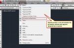
To edit in place, you can enter the REFEDIT command and select a block, or select a block and select in the context menu In-context block editing

As you can see, the block's environment has darkened, but is available for binding.

After creating the desired geometry, you must press the button Save Changes on tape