In many cases, it is necessary to insert a scan, a picture, a map, a photo, a raster format diagram or another image into AutoCAD as a background, in order to work on it with the vector tools of AutoCAD.
Important: To avoid problems when transferring drawing files and underlays, copying to other folders - place DWG drawing files and inserts (images) together in the same folder. Or underlays in the Underlays subfolder.
Although Autodesk Autocad is a vector editor, it has some capabilities for working with bitmaps. Shown here using Autocad 2013 as an example.
So, to insert a picture, use the insert menu.
If you are using the AutoCAD Classic interface, to insert a scanned image or picture into AutoCAD, select the menu "Insert" - Bitmap:

In the window that appears, select the required file:

To insert a picture into AutoCAD correctly- you need to specify the required parameters. For example, try to indicate "Relative" path to the image, this will avoid losing the underlay when moving or copying the DWG drawing. When you select the scale with a tick "Specify on screen"- after pressing the OK button, you can specify the scale manually with the mouse. Usually indicate 1 (then it can still be changed by means of AutoCAD scaling), or another coefficient. "Insertion point" - you can specify the exact coordinates, or just poke on the screen and then move the background, if necessary.

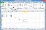
We decided on the parameters, click OK. An image frame will appear:

Click the mouse (if the insertion point is "Specify on screen") - the picture will appear in the workspace of the AutoCAD model. By the way, in the "Sheet" space, substrates are inserted analogously.

Advice: If possible, try to use black-and-white (monochrome) images in TIF format with compression as substrates, for example CCiTT FAX 4. It is more convenient to work with them visually in AutoCAD, because they do not have a background, and also take up little disk space and RAM.
Here is an example of an inserted black and white (not to be confused with grayscale) image:

How to remove the outline of an image inserted into AutoCAD?
If the "extra" frame of the inserted picture interferes with printing and work, it can be disabled with the command: " IMAGEFRAME 0". Include outline:" IMAGEFRAME 1".
Or through the menu "Edit" - "Object" - "Image" - "Contour". You may need to access this menu enable menu bar in AutoCAD, through the item "Show menu bar".

Then "Edit" - "Object" - "Image" - "Contour". By the way, there are also many more interesting menu items for working with various AutoCAD objects.

Keep in mind that after turning off the image outline, you will not be able to select it, and accordingly move it and do other operations. To do this, you will need to turn on the picture frame again, in the same way.
The concept that the company is guided by is the priority of quality in everything due to compliance with the requirements of the modern market, continuous improvement of the effectiveness of the management system, quality and monitoring of completed projects
Inventory, accounting of green spaces, entering inventory data into the AIS "Register of green spaces" in Moscow, making a "Territory Improvement Passport"
Primary activity inventory of green spaces, accounting for green spaces, making passports for improvement of the territory, entering data into the AIS Register of green spaces, agreeing on the passport for improvement of the territory in the JKKHiB and DPiOOS.
We have been taking inventory and certification of green spaces and road facilities in Moscow for 9 years.
During this time, we have inventoried about 5,000 hectares:
Landscaped areas 1,2,3 categories of content,
Forests, parks, squares, roads, courtyards, incl.
Alexander Garden (garden near the Moscow Kremlin),
Kremlin embankment, green areas on Red Square near GUM,
Novy Arbat, Pokrovsky Cathedral, shopping and entertainment complex "Manezh",
Solntsevo district, Vernadsky Avenue district, Dorogomilovo district, Troparevo-Nikulino district,
District Vykhino-Zhulebino, Lefortovo, Maryino, Nekrasovka, Ryazansky
Southern Administrative District,
South-Eastern Administrative District,
Districts of New Moscow (TiNAO),
Squares and parks of the Central Administrative District,
Green areas along the MKAD,
Green areas along the Third Ring Road,
Vnukovo airport,
All-Russian Dispatch Center Vnukovo,
All radial highways in Moscow (Shchelkovskoye highway and Entuziastov highway, Altufevskoye and Yaroslavskoye highways, Kashirskoye and Varshavskoye highways, Mozhayskoye and Rublevskoye highways, Volokolamskoye and Zvenigorodskoye highways, Mezhdunarodnoe highway, Kievskoye highway, etc.)
A large number of hospitals, polyclinic (GBUZ), schools (GBOU), industrial and commercial territories, and this is not an exhaustive list of territories that we have stockpiled.
Grounds for performing work on the inventory of green spaces in Moscow:
Decree of the Moscow Government dated August 12, 2014 No. 461-PP “On the automated information system“ Register of green spaces ”(as amended on October 4, 2017)”;
Resolution of the Moscow Government dated September 10, 2002 N 743-PP (as amended on October 4, 2017) "On approval of the Rules for the creation, maintenance and protection of green spaces in the city of Moscow";
Decree of the Moscow Government dated September 2, 2014 No. 501-PP "On the development of passports for the improvement of courtyard territories, amending the legal acts of the city of Moscow and invalidating the legal acts of the city of Moscow";
Law of the city of Moscow dated 05.05.1999 No. 17 "On the protection of green spaces" (as amended on May 7, 2014).
The inventory of the territories of the green fund of the city of Moscow is carried out in order to:
Obtaining reliable data on the state of green spaces, species, age composition, on the quantitative and area characteristics of natural communities, elements of integrated improvement for urban management at all levels of management, operation and financing;
Obtaining information on the location of green spaces, elements of complex improvement on the territory of the green fund of the city of Moscow, indicating the rights holders of land plots of the territory responsible for its safety and condition;
Determination of the conformity of the activities carried out by the rightholders of the land plots of the territory of the green fund of the city of Moscow at the greening objects, the established purpose of the territories;
Analysis of the state of the green fund of the city of Moscow;
Determination of land plots occupied by various types of plantations, infrastructure or other elements in their composition;
Information support for the preparation of planning projects for natural, specially protected natural (hereinafter - specially protected natural areas) (for which there are no plans for planning), specially protected green areas (hereinafter referred to as SPNT), green areas and other territories occupied by green spaces in the city of Moscow;
Development of measures for the preservation and restoration of natural communities and recommendations for the management of land plots; infrastructure and improvement elements in specially protected natural and other natural areas for the revision period for the management of the State Budgetary Institution "Moscow City Administration of Natural Territories";
Determination of the effectiveness of reforestation work, the quality state of the created forest cultures, their compliance with the current standards and technical conditions. These materials make it possible to determine measures to improve the condition of crops;
Development of proposals for adjusting plans for the planning of protected areas, natural, green areas and other areas occupied by green spaces, the city of Moscow, territorial schemes for the development of protected areas in the city of Moscow;
Regulation of work and determination of costs for the preservation and maintenance of natural communities, green spaces, landscaping elements and complex improvement and overhaul on the territory of the green fund of the city of Moscow (based on the obtained characteristics of the state of the elements of landscaping and complex improvement);
Drawing up a title list for green spaces, elements of landscaping and complex improvement for the calculation of natural indicators for the territories of the green fund of the city of Moscow;
Preparation of data for filling the State Cadastre of Protected Areas of the City of Moscow, the Automated Information System "Register of Green Spaces", the Automated Control System "United Dispatch Service of the Department of Housing and Communal Services and Improvement of the City of Moscow" (hereinafter - the ACS "ODS DZHKHiB"), other information systems of the city Moscow, if such is established by the legislation of the Russian Federation and the city of Moscow.
Types of work on certification of green spaces:
1.Conducting preparatory work
Obtaining the boundaries of the inventory territory;
Reconnaissance survey of the inventory territory;
Establishment of the area of the inventory territory;
Establishing the classification of the inventory object
Determination of the location of trees in nature in the inventory territory;
Determination of the location of the bush in nature in the inventory territory;
Collection of general information about the inventory territory (including administrative-territorial affiliation;
Indication of the responsible land user;
Establishment of the status of the object, the functional purpose of the land plot;
2.Conducting field work on inventory of green areas:
Geodetic survey of the inventory area using geodetic equipment and local measurements;
Determination of woody vegetation in kind, numbering in kind, measurement of diameter, age, height, description of the state;
Determination of shrub vegetation in kind, numbering in kind, measurement of diameter, age, height, description of the state;
Determination of the state of lawns, measurement of the area, description of quality characteristics, determination of the type of lawn;
Description of flower beds, measuring the area, assigning a serial number, determining the type of flower garden, planted plant material;
Description of the road and path network, determination of the condition, type of coverage, purpose, measurement of the area;
Determination of the location of the LFA and improvement elements, their quantity, numbering, characteristics and description of the state;
Definition of buildings and structures in the inventory area, their purpose and area measurement;
Determination of plane structures, their type, area and coverage;
Determination of the elements of the organization of the relief, their type, area;
Determination of functional support systems, their type and number;
Collection of information about repair work;
Collection of additional information (date of the last repair or reconstruction, mode of urban planning activities);
3.Conducting office work on inventory of green areas:
Creation of an inventory plan of the object M1: 500, with registration in accordance with the decree of the Government of Moscow dated 04.10.2005, No. 770-PP "On methodological recommendations for the preparation of dendrological plans and counting lists";
Applying trees and shrubs to the plan with the assignment of ordinal numbering in accordance with the list of green spaces;
Calculation of the total area of the object, and entering the data into the statement;
Drawing flower beds on the plan, calculating their areas and entering into a statement;
Drawing on the plan of buildings and structures, calculating their areas and entering them into a statement;
Calculation of the operational area of the object and entering the data into the statement;
Drawing planar structures on the plan, calculating their areas and entering them into a statement;
Drawing on the plan of the road and path network, calculating its areas and entering into the statement;
Drawing a lawn on a plan, calculating areas and entering into a statement;
Drawing on the LFA plan, miscalculation by quantity and entering into the statement by type;
Drawing on the plan of functional support systems, miscalculation by quantity and entering into a statement by type;
Drawing on the plan of the elements of the organization of the relief, calculating the areas and entering into the statement;
Data collection and printing of field records on a computer;
Calculation of the total number of trees in the facility;
Calculation of the total number of shrubs on site;
Calculation of transplanted trees on site;
Calculation of transplanted shrubs on site;
Calculation of cut trees at the facility;
Calculation of cut down shrubs on site;
Calculation of the stored trees on the object;
Calculation of preserved shrubs on site;
Drawing up the balance of the territory;
4. Conduct cartographic works:
Ensuring electronic registration of landscaping objects and green spaces when maintaining AIS "Register of green spaces" and monitoring green spaces;
Drawing up a topographic plan in electronic form with reference to the Unified State Cartographic Framework of the City of Moscow in formats that provide free import of data into geographic information systems;
Registration of an inventory plan in accordance with the existing requirements M1: 500;
Approval of the Territory Improvement Passport in electronic form in the Department of Housing and Communal Services and the Department of Natural Resources and Environmental Protection.
We are proud of the work done, because our main principle in any work is honesty, integrity, and love for the business you are doing.

Completed projects
News: 2 April 2015 New requirements for approvals of the Territory Improvement Passport Instructions on how to approve the Customer's passport in the Register. 30 March 2015 Clarifications on changes in the requirements for passports for the improvement of the territory (accounting area) In the passport of the accounting site, the name (Passport of the territory improvement) and the procedure for approval have changed. 29 March 2015 For a green space passport. From Decree N 743-PP dated 12.12.2014. Methodology for conducting an inventory in the territories of the green fund of the city of Moscow Published information from the decree on the methodology of inventory of green spaces in Moscow March 29, 2015
Note: AutoLISP programs can only be run on the full version of AutoCAD, they do not work under AutoCAD LT. (excluding the cases of downloading additional applications such as LT Extender and the like, which are specially designed to run lisp and (or) arx applications in the AutoCAD LT environment.)
Saving the program code on your computer
Using the cursor, select this code and copy it to the clipboard by right-clicking and selecting Copy(or Ctrl + C).
Launch Notepad and paste our code using the menu Edit >> Insert(or Ctrl + V):
The code:
| (defun C: OFF2 (/ d obj ent adoc * error * undo lays Flag) (defun * error * (msg) (vla-EndUndoMark adoc)) (vl-load-com) (setq adoc (vla-get-activedocument ( vlax-get-acad-object)) lays (vla-get-layers adoc)) (vla-StartUndoMark adoc) (setvar "CMDECHO" 0) (if (null * OFF2 *) (setq * OFF2 * (abs (getvar " OFFSETDIST ")))) (if (zerop * OFF2 *) (setq * OFF2 * 1)) (setq d (getvar" UNDOCTL ")) (cond ((= d 0) (vl-cmdf" _.UNDO "" _All ")) ((= d 3) (vl-cmdf" _.UNDO "" _Control "" _All ")) (t nil)); _ end of cond (princ" \ n Offset value: ") (initget 6 ) (if (null (setq d (getdist))) (setq d * OFF2 *)) (setq * OFF2 * d undo 0 Flag t) (initget "Undo Undo Undo G J Exit Exit U D _Undo Undo Undo Undo Exit Exit Exit Exit ") (while Flag (setq obj (entsel (strcat" \ n Select object ["(if (not (zerop undo))" Cancel / "" ")" Exit]: "))) (cond ((= obj "Undo") (if (not (zerop undo)) (progn (vl-cmdf "_UNDO" "_B") (setq undo (1- undo))) (alert "Nothing more to undo"))) ((= obj "Exit") (setq Flag nil)) ((null obj) (if (= (get var "ERRNO") 52) (setq Flag nil) (princ "*** Past ***"))) (t (setq ent (vlax-ename-> vla-object (car obj))) (cond (( = (vla-get-lock (vla-item lays (vla-get-layer ent))): vlax-true) (alert "On the locked layer!")) ((vlax-method-applicable-p ent "Offset) (vl-cmdf "_UNDO" "_M") (setq undo (1+ undo)) (vla-offset ent d) (vla-offset ent (- 0 d))) (t (alert "Unable to create object like this "))))) (initget" Undo Undo G J Exit Exit U D _Undo Undo Undo Exit Exit Exit Exit ")) (vla-EndUndoMark adoc) (princ)) (princ" \ nType OFF2 ") ) |
After inserting the code into notepad, we should have something like this:
Now we have to save the file. The file can be named whatever you like, but it must have an extension .LSP... It would be more correct (but not necessary) to name the file the same as the command name in the code you found. The command is always preceded by a prefix C: after the word defun... In the example above, you can see that the command was named OFF2, respectively, the file is called off2.lsp... This way we can avoid clutter because we will know what is in the file off2.lsp there is a team OFF2.
Sometimes several functions are presented in the code. It is necessary to find the "main". Such a function is either prefixed WITH:, or the author of the code himself specifies what "to use as". In the case of multiple "masters", the naming of the file cannot be of any recommendation.
Loading lisp file
Next, launch AutoCAD and select Service >> Autolisp >> Download (Tools >> AutoLISP >> Load _appload.
We should see a dialog box as shown below:

Use the following sequence to download off2.lsp:
- Navigate to the folder where you saved the lisp file.
- Select the file you want to download from the list.
- Click the button Download.
(If everything went well, you should see the inscription "off2.lsp successfully loaded") - Click the button Close to complete the command.
Team or function?
First you need to decide what we have: a team or a function?
A bit of theory.
In the description of almost any code, there is a line like
It can be called (provided that it is loaded) from the command line directly:
Command: test
And actions will be performed
But this one:
Then on the command line you need to type command_name> without a prefix C:.
Tips: You can also load the lisp file by drag and drop ( drag-and-drop) file icons in the graphic window of an open AutoCAD document.
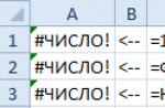
AutoCAD; error: no function definition:
If your function or command does not work or exits with a message like in the example below, then a simple method can help you.
Your lisp should now work without error.
What is this (vl-load-com)?
This function loads a large number of functions included in the AutoLisp extension, which allows you to work with ActiveX objects, properties, methods and events. An indication of the need to load the AutoLisp extension is the presence in the text of your program of functions starting with prefixes vla-(For example vla- get-activedocument), vlax-(For example vlax- get-acad-object), vl-(For example vl- catch-all-apply) and vlr-(For example vlr- pers).
It never hurts to add anyway (vl-load-com) to the beginning of the file to avoid such errors.
Organization of a library of lisp files.
What if there are enough files? Dial each time _appload to download this or that application? Organizing your library will be most effective. First, let's agree that we will put all our files in one folder. For instance, D: \ MyLisp... Let's register this folder in the AutoCAD access paths. For this we choose Service >> Customization (Tools >> Options) or type in the command line _options... Go to the bookmark Files (Files) and expand the list Access path to support files (Support File Search Path).
We should see a dialog box as shown below:

Use the following sequence to register the folder in the access paths:
- Click the button Add.
- Click the button Overview and select the target folder (in our case, D: \ MyLisp)
- The folder path should appear in the dialog box.
- Click the button OK to complete the command.
Now our folder is registered in the AutoCAD access paths. What does it give us? We can load our files without specifying a specific path, but only the file name.
We can type on the command line (load "") to load the required code like (load "off2")... Note that adding an extension .lsp optional, although not prohibited.
And, finally, and most importantly, this will allow us to create panels with buttons for loading a particular program. The button will have the following content:
^ C ^ C (if (null C:) (load "")) ;;
In our case:
^ C ^ C (if (null C: OFF2) (load "off2")); OFF2;
Autoloading files.
If there is a need to load your lsp files when opening a drawing, then you need to add the necessary files to the autoloading list.
Launch AutoCAD and select Service >> Autolisp >> Download (Tools >> AutoLISP >> Load) or type in the command line _appload.
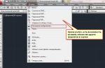
In the dialog box that opens, click on the button Applications next to the portfolio image

In the next dialog box, click on the button Add and point to the required files.

They should appear in the list of applications.
Now the listed files will be loaded every time you open a picture.
It is important to understand that (at least in the full version of AutoCAD) loading applications placed in Autoload (Startup Suite), as a rule, is executed in all profiles and sessions of AutoCAD "a.
Besides, there is one more point. If there are 2 or more files that describe functions with the same name, the one that was loaded last will be executed. Since it is impossible to predict the sequence in which applications will be loaded, such situations should be avoided.
The process of inserting blocks into a drawing is much the same as inserting individual objects. In this case, you can change the scaling or rotate the block to the desired level. You can also design a dynamic block with various scaling and copy rotation angles. We will talk about blocks of this type a little later.
How to insert blocks into drawings
To insert a block into a drawing file, you will need to follow these steps:
- Call the block insert window.
a) enter "Paste" into the command line.
b) execute the commands Insert> Block.
c) Click the corresponding icon in the block panel.
- We select to insert a block or a separate file.
a) To insert a block from the working drawing, select the desired option from the "Name" window.
b) Insert the file using the "Browse" option.
3.Set the flag next to the option "Specify on screen". We assign it to the insertion point, scale and rotation angle.
- We also put a check mark in the "Equal scales" option.
- Finally, check or uncheck the Explode function.
- We complete the process by choosing the "Ok" option.
- The software will automatically ask you to specify the necessary parameters if they were not specified earlier:
- Specify the insertion point, as described in the first lesson, the insertion point coincides with the base point of the block.
- Specify the scale of the inserted block, the default scale is 1: 1. In order to change the scale along the axes, when prompted to enter the scale, enter X at the command line. After that, the command will ask you to enter the scale along the axis X and axes Y... For 3D models, entering the scales along the axes is similar. Specifying a negative scale along one axis creates a mirror image about the second axis.
- You can specify the angle of rotation either by entering the angle value in the command line, or by specifying the angle points with the cursor.
When inserting a drawing file, paper space objects are not included in the insert, in order to insert such objects, you must define them in the block.
How to work with DesignCenter
DesignCenter is an explorer window that helps you select one block from already saved drawings or a library with a preview option.
Select the block and insert it into the drawings
- Open DesignCenter and hold down ctrl + 2.
- We indicate the direct path to the folder with the desired file using the explorer.
- Open the desired drawing in the open folder.
- This will give the user access to all parameters and attributes.
- Select the blocks tab.
- We look at a row of icons with blocks of the selected drawing.

To insert a block, you will need to carry out a procedure similar to the one described above.
To insert a block, you can simply drag it to the field of an open drawing. The program will automatically prompt the user to edit the drawing. You can insert many blocks of different types, sizes and contents into one drawing.
We are ending our tutorial on inserting blocks and filesystems. Next, we will talk about working with their management and library sections.
Fine-tuning the user interface allows you to add your own functions, keyboard shortcuts, mouse key combinations, and change standard panels to the functionality of the standard AutoCAD interface.
This manual is useful for an experienced user who understands which tools he uses often, and which tools are not used at all, or which are lacking.
Benefits of Fine-tuning the interface
1. Setting up the interface clearly for yourself
2. Adding your own commands
3. Removing unnecessary buttons
4. Adding speed dialing keys
After installing AutoCAD and initial configuration, we get the following interface
I will describe the disadvantages of the layout of this interface:
- All panels are scattered around the perimeter of the screen;
- There are buttons in the toolbars that are not used;
- Command line enabled (reduces visible space);
- Included unnecessary toolbars
Fine-tuning the interface
1. Organization of toolbars
We include all commonly used toolbars. I will give my list
As shown in the figure, all panels are grouped in the upper left corner (as it seems to me, we are used to perceiving information from left to right)
2. Configuring the command line:
- Ctrl + F9(In AutoCAD< 2010 версии)
- Drag the command line to the model field and set the opacity to 0%.
 |
| Fig. 3 Command line transparency. |
3. Customize the toolbar.
To start customizing the toolbar, run the command: _CUI(Customize User Interface)
Here you can configure:
- Quick Launch Panel;
- Ribbon (for a "ribbon" interface);
- Toolbar (toolbars);
- Keyboard shortcuts, etc.
Let's create our own toolbar and name it "SCSENG_TOOLBAR"
Go to the section: Toolbar -> RMB -> New Toolbar
Only registered functions and commands. How to register a function in the article "Automating routine tasks or using scripts Lisp, ARX, etc.".
Add to the panel "SCSENG_TOOLBAR"
Commands: " dlina "," plus1 "," Deselect All ".
Drag the created panel.
Button " Deselect All " allows you to quickly reset selected objects (very convenient when you need to copy or select a lot).
All adding buttons is ready.
3.2 Removing unnecessary buttons
In the toolbar, right-click and delete unnecessary buttons.
By removing unnecessary buttons, we save panel space. This is especially useful when using small screen sizes.
3.3 Customizing keyboard shortcuts
4. Saving the configured interface
After adjusting the location of toolbars, keyboard shortcuts, you need to save your workplace.
 |
| Rice. 12. Preservation of the workplace |