The simplest and most accessible way for radio amateurs to measure the inductance of a low-frequency coil (low-frequency inductor, steel-core transformer winding, etc.) is as follows:
1) assemble the circuit shown in Fig. ; as a device that measures the voltage across the variable resistor R and the coil L x use a tester or a separate AC voltmeter; the maximum value of the resistance of the resistor with a dissipation power of 0.25-1-0.5 W is chosen in the range of 100-30000 ohms (depending on the expected value).
2.32. Measurement of inductances of low-frequency coils
2) install with autotransformer AT voltage at 10 V and notice the reading U 1 voltmeter, that is, the voltage drop across the investigated coil;
3) move the switch slider from the position 1-3 into position 1-2 , thus connecting a voltmeter in parallel with the resistor, and select such a resistance value R = R2, at which the voltage drop across the resistor is also equal to U 1.
4) calculate the inductance of the coil according to the formula:
L "x \u003d 0.00318 √ RR 2 Gn, (32)
where R1 and R2- resistance of the resistor (Ohm) when the switch slider is in positions 1-3 and 1-2.
In the absence of a variable resistor, the inductance of the coil is measured using a fixed resistor. The scheme and measurement process remain the same, the formula for counting L x- complemented by a multiplier U1/U2, that is, it takes the form:
L "" x \u003d 0.00318 R (U 1 / U 2) Gn, (33)
where R- resistor resistance, Ohm,
U 1 and U 2- voltmeter readings in positions 1-3 and 1-2 of the switch slider.
In most cases, the inductive reactances of the windings are much higher than their active resistances, so the above formulas give fairly accurate inductance values.
However, if the number of turns of the coil is small, and the resistance to direct (or alternating) current is large (several tens or hundreds of ohms), then L" x and L"" x calculated according to other, more precise formulas, namely:
where R- resistance of the resistor when the switch slider is in position 1-2; U- voltage on series-connected R and L x; U 2- the voltage across the resistor is equal to the voltage U 1 on a reel L x;
L x "= 0.00318 R 0 / tg α,
where R- active resistance of the winding;
α - the angle formed by the side BC of the triangle ABC () and the perpendicular dropped from point B to the continuation of the side LS.

Rice. 2.40. Stress triangle defining angle α
Angle tangent α find so. Set aside on an arbitrary line MN() section AC, proportional to voltage U 2 on a resistor R. Then draw from points A and WITH, as from centers, with radii proportional to stress U power supply and voltage U 1 on the winding, two arcs. connect the dot V intersection of these arcs with a point WITH and lowered from the point V perpendicular BD directly MN. In conclusion, lengthen the height BD triangle ABC up to 100 mm (cut DK) and pass through the point TO direct KP, parallel to the side sun triangle ABC. If we take the segment DK per unit, then cut off at the same time on a straight line MN section PD and will be numerically equal to the tangent of the angle α .
In cases where the resistance of the coil to direct current exceeds its inductive resistance, the measurement L x carried out at a different, higher frequency (for example, 400 or 800 Hz). The shape of the voltage curve at the output of the voltage source of this increased (audio) frequency must be sinusoidal.

Rice. 2.41. On the question of finding the tangent of an angle α
When switching to a frequency not equal to 50 Hz, formulas (32) ~ (35) are introduced instead of the coefficient 0,00318 factor 1/2πf circuit power supply, where f- frequency of the circuit power supply.
Devices for direct evaluation and comparison
Measuring instruments for direct assessment of the value of the measured capacitance include microfaradmeters, the action of which is based on the dependence of the current or voltage in the alternating current circuit on the value included in it. The capacitance value is determined on the scale of the pointer meter.
More widely used for measurement and inductances balanced AC bridges, allowing to obtain a small measurement error (up to 1%). The bridge is powered by generators operating at a fixed frequency of 400-1000 Hz. As indicators, rectifier or electronic millivoltmeters, as well as oscilloscope indicators, are used.
The measurement is made by balancing the bridge as a result of alternating adjustment of its two arms. The readings are taken from the limbs of the handles of those shoulders with which the bridge is balanced.
As an example, consider measuring bridges, which are the basis of the EZ-3 inductance meter (Fig. 1) and the E8-3 capacitance meter (Fig. 2).

Rice. 1. Diagram of a bridge for measuring inductance

Rice. Fig. 2. Bridge circuit for measuring capacitance with small (a) and large (b) losses
When the bridge is balanced (Fig. 1), the inductance of the coil and its quality factor are determined by the formulas Lx = R1R2C2; Qx = wR1C1.
When balancing bridges (Fig. 2), the measured capacitance and loss resistance are determined by the formulas

Measurement of capacitance and inductance using the ammeter-voltmeter method
To measure small capacitances (no more than 0.01 - 0.05 μF) and high-frequency inductors in the range of their operating frequencies, resonant methods are widely used. The resonant circuit usually includes a high-frequency generator, inductively or through a capacitance connected to the measuring LC circuit. As resonance indicators, sensitive high-frequency devices are used that respond to current or voltage.

Using the ammeter-voltmeter method, relatively large capacitances and inductances are measured when the measuring circuit is powered from a low-frequency source of 50 - 1000 Hz.
For measurements, you can use the diagrams in Fig. 3.

Figure 3. Schemes for measuring large (a) and small (b) resistances to alternating current
According to the readings of the instruments, the impedance
![]()
where

from these expressions it is possible to determine

When active losses in a capacitor or inductor can be neglected, the circuit of Fig. 4. In this case


Rice. 4. Schemes for measuring large (a) and small (b) resistances using the ammeter - voltmeter method

Measuring the mutual inductance of two coils
Coils inductances are elements in the marking of which the parameters are usually not indicated. In addition, often the coils are wound independently. In both cases, determine inductance coil is only allowed by measuring it. It can be carried out in different ways, involving the use of equipment of varying difficulty. Some of these ways are thoughtful and require calculations. But direct-reading LC meters are free from these shortcomings, they allow you to measure inductance quickly and without additional calculations.
You will need
- Direct-reading LC meter or multimeter with inductance measurement function
Instruction
1. Buy an LC meter. In most cases, they are similar to ordinary multimeters. There are also multimeters with the function of measuring inductance - such a device will suit you too. Any of these devices can be bought in specialized stores selling electronic components.

2. De-energize the board on which the coil is located. If necessary, discharge the capacitors on the board. Solder the coil inductance which you want to measure, from the board (if this is not done, a noticeable error will be introduced into the measurement), and then connect to the input jacks of the device (to which ones, it is indicated in its instructions). Switch the instrument to the most accurate limit, usually indicated as “2 mH”. If inductance coils smaller than 2 millihenries, then it will be determined and shown on the indicator, after which the measurement can be considered completed. If it is larger than this value, the device will show an overload - a unit will appear in the highest digit, and spaces in the rest.
3. In case the meter showed overload, switch the device to a further, more audacious limit - “20 mH”. Please note that the decimal point on the indicator has moved - the scale has changed. If the measurement doesn't make a splash this time, keep switching the limits to more daring ones until the overload disappears. Read the summary later. After looking at the switch after that, you will find out in what units this total is expressed: in henry or in millihenry.
4. Disconnect the coil from the input sockets of the device, then solder it back to the board.
5. If the device shows zero even at the most accurate limit, then the coil either has a very small inductance, or contains short-circuited turns. If, even at the most daring limit, an overload is indicated, the coil is either broken or has too much inductance which the instrument is not designed to measure.
In order to measure inductance coils, use an ammeter, voltmeter and frequency meter (in case the frequency of the AC source is not known), then take readings and calculate inductance. In the case of a solenoid (a coil whose length is much larger than its diameter), to determine the inductance, you need to measure the length of the solenoid, its cross-sectional area and the number of turns of the conductor.

You will need
- inductor, tester
Instruction
1. Measuring inductance using a voltmeter-ammeter method. In order to detect inductance conductor in this way, use an alternating current source with a driven frequency. If the frequency is not known, then measure it with a frequency meter by connecting it to the source. Connect a coil to the current source, inductance which is being measured. After that, stepwise turn on the ammeter in the circuit, and in parallel to the ends of the coil - a voltmeter. After passing the current through the coil, take the readings of the instruments. Accordingly, the current strength in amperes and voltage in volts.
2. From this data, calculate the value of the inductance of the coil. To do this, divide the voltage value in steps by 2, the number 3.14, the values of the frequency of the current and the strength of the current. The result will be the value of the inductance for this coil in Henry (H). Main note: connect the coil only to an alternating current source. The energetic resistance of the conductor used in the coil should be slightly negligible.
3. Measuring the inductance of a solenoid. To measure the inductance of a solenoid, take a ruler or other tool for determining lengths and distances, and determine the length and diameter of the solenoid in meters. After this, count the number of its turns.
4. After that, discover inductance solenoid. To do this, raise the number of its turns to the second power, multiply the result by 3.14, the diameter to the 2nd power and divide the result by 4. Divide the resulting number by the length of the solenoid and multiply by 0.0000012566 (1.2566 * 10-6) . This will be the value of the inductance of the solenoid.
5. If there is such a possibility, use a special device to determine the inductance of this conductor. It is based on a circuit called an AC bridge.
An inductor is capable of storing magnetic energy when an electric current flows. The main parameter of the coil is its inductance. Inductance is measured in Henry (H) and is denoted by the letter L.

You will need
- Inductor parameters
Instruction
1. The inductance of a short conductor is determined by the formula: L = 2l(ln(4l/d)-1)*(10^-3), where l is the length of the wire in centimeters and d is the diameter of the wire in centimeters. If the wire is wound on the frame, then an inductor is formed. The magnetic flux is concentrated, and, as a result, the value of the inductance increases.
2. The inductance of the coil is proportional to the linear dimensions of the coil, the magnetic permeability of the core and the square of the number of winding turns. The inductance of a coil wound on a toroidal core is: L = ?0*?r*s*(N^2)/l. In this formula, ?0 is the magnetic continuous, ?r is the relative magnetic permeability of the core material, which depends on the frequency), s is the cross-sectional area of the core, l is the length of the center line of the core, N is the number of turns of the coil.
3. The inductance of the inductor in µH can also be calculated using the formula: L = L0*(N^2)*D*(10^-3). Here N is the number of turns, D is the diameter of the coil in centimeters. The index L0 depends on the ratio of the length of the coil to its diameter. For a single-layer coil, it is: L0 = 1/(0.1*((l/D)+0.45)).
4. If the coils are connected stepwise in the circuit, then their total inductance is equal to the sum of the inductances of all coils: L = (L1 + L2 + ... + Ln) If the coils are connected in parallel, then their total inductance is: L = 1 / ((1 / L1) + ( 1/L2)+…+(1/Ln)).
Related videos
The inductance of a coil can be measured spontaneously or indirectly. In the first case, you will need a direct-reading or bridge device, and in the second you will have to use a generator, a voltmeter and a milliammeter, and then carry out a series of calculations.

You will need
- - direct-reading or bridge inductance meter;
- – sinusoidal voltage generator;
- – AC voltmeter and milliammeter;
- – frequency meter;
- - scientific calculator.
Instruction
1. In order to measure the inductance with a direct-reading device, connect a coil to it, and then, stepwise selecting the measurement limits with a switch, select one of them so that the result is approximately in the middle of the range. Read the summary. If the meter has an analog scale, take the division value into account when reading the total, as well as the value indicated next to the corresponding switch location.
2. On the bridge device, after the entire range switching, move the axle balancing knob to any of the extreme positions, and then turn it all the way in the opposite direction. Find the range in which this knob is allowed to balance the bridge. Having achieved the disappearance of the sound in the speaker or headphones or the decrease in the readings of the dial indicator to zero, read the readings on the scale of the regulator (but not the dial gauge). At the same time, as in the previous case, consider the price of the division and the indicator for the one that should be multiplied in this reading range.
3. To measure inductance indirectly, assemble a measuring circuit. An AC voltmeter, switched to the limit at which the upper limit of the range corresponds to a voltage of several volts, connect in parallel with the generator output. Connect the frequency meter there as well. Also, in parallel with them, connect a series circuit consisting of the inductor under test, as well as an AC milliammeter. Both devices are required to show the actual, and not the amplitude values of the measured quantities, and also be designed for a sinusoidal waveform.
4. On the generator, turn on the sinusoidal voltage generation mode. Get the voltmeter to show about 2 volts. Increase the frequency until the milliammeter reading begins to decrease. Get them reduced to about half the original value. Select the limit on the frequency meter that corresponds to the measured frequency. Read the readings of all 3 instruments, and then turn off the generator and disassemble the measuring circuit.
5. Convert instrument readings to SI units. Divide the voltage by the current. The inductive reactance of the coil will be obtained at the frequency at which the measurement was carried out. It will be expressed in ohms.
6. Calculate the inductance using the formula: L=X/(2?F), where L is the frequency, G (henry), X is the inductive reactance, Ohm, F is the frequency, Hz. If necessary, convert the result of the calculation to derived units (say, millihenry, microhenry).
Note!
Do not touch the elements of the measuring circuit when it is energized.
Related videos
Note!
Never connect an LC meter to a live circuit.
Useful advice
Some LC meters have a special adjustment knob. Read the instructions for the device on how to use it. Without adjustment, the instrument readings will be inaccurate.
When working with any electrical appliances or conductive parts, the presence of measuring equipment is necessary, be it an ammeter, voltmeter or ohmmeter. But in order not to buy all these devices, it is better to get a multimeter.
The multimeter is a universal measuring device that allows you to measure any characteristic of electricity. Multimeters are either analog or digital.
Analog multimeter
This type of multimeter displays measurement readings with an arrow, under which a display with different scales of values \u200b\u200bis installed. Each scale displays the readings of a particular measurement, which are signed directly on the scoreboard. But for beginners, such a multimeter will not be the best choice, since it is rather difficult to understand all the symbols that are on the scoreboard. This may lead to incorrect understanding of the measurement results.
Digital multimeter
Unlike analog multimeters, this multimeter makes it easy to determine the quantities of interest, while its measurement accuracy is much higher compared to pointer devices. Also, the presence of a switch between different characteristics of electricity eliminates the possibility of confusing one or another value, since the user does not need to understand the gradation of the reading scale. The measurement results are displayed on the display (in earlier models - LED, and in modern ones - LCD). Due to this, the digital multimeter is comfortable for professionals and simple and straightforward to use for beginners.

Multimeter inductance meter
Although it is rare to determine the inductance when working with electronics, it is still sometimes necessary, and multimeters with the measurement of inductance are difficult to find. In this situation, a special attachment to the multimeter will help, which allows you to measure the inductance.

Often, for such a set-top box, a digital multimeter is used that is set to measure voltage with a measurement accuracy threshold of 200 mV, which can be purchased at any store of electrical and radio equipment in finished form. This will allow you to make a simple prefix to a digital multimeter.
Set-top board assembly.
You can assemble a tester attachment to a multimeter for measuring inductance without any problems at home, having basic knowledge and skills in the field of radio engineering and soldering microcircuits.
In the board circuit, transistors KT361B, KT361G and KT3701 with any letter markers can be used, but to obtain more accurate measurements it is better to use transistors marked KT362B and KT363. These transistors are installed on the board in positions VT1 and VT2. At position VT3, it is necessary to install a silicon transistor with a p-n-p structure, for example, KT209V with any letter marking. Positions VT4 and VT5 are intended for buffer amplifiers. Most high-frequency transistors will do, with h21E parameters for one not less than 150, and for the other more than 50.
For positions VD and VD2, any high-frequency silicon diodes are suitable.
The resistor can be selected MLT 0.125 or similar. Capacitor C1 is taken with a nominal capacity of 25330 pF, since it is responsible for the accuracy of measurements and its value should be selected with a deviation of no more than 1%. Such a capacitor can be made by combining thermostable capacitors of different capacities (for example, 2 at 10000 pF, 1 at 5100 pF and 1 at 220 pF). For other positions, any small-sized electrolytic and ceramic capacitors with an allowable spread of 1.5-2 times are suitable.
Contact wires to the board (position X1) can be soldered or connected using spring clips for "acoustic" wires. Connector X3 is designed to connect the set-top box to.
It is better to take a shorter wire to the "bananas" and "crocodiles" in order to reduce the influence of their own inductance on the measurement readings. In the place where the wires are soldered to the board, the connection should be additionally fixed with a drop of hot melt adhesive.
If it is necessary to adjust the measurement range, a connector for a switch can be added to the board (for example, for three ranges).
Housing for the multimeter
The case can be made from a ready-made box of a suitable size or you can make the box yourself. You can choose any material, for example, plastic or thin fiberglass. The box is made to the size of the board, and holes are prepared in it for its fastening. Holes are also made for wiring. Everything is fixed with small screws.

The set-top box is powered from the mains using a 12 V power supply.
Setting up an inductance meter
In order to calibrate the inductance measuring attachment, you will need several induction coils with a known inductance (for example, 100 μH and 15 μH). The coils are connected in turn to the attachment and, depending on the inductance, the value of 100.0 for a 100 μH coil and 15 for a 15 μH coil with an accuracy of 5% is set by the trimmer resistor engine on the multimeter screen. Using the same method, the device is tuned in other ranges. An important factor is that for an accurate calibration of the attachment, the exact values of the test inductors are needed.
An alternative method for determining inductance is the LIMP program. But this method requires some preparation and understanding of the program.
But both in the first and in the second case, the accuracy of such inductance measurements will not be very high. This inductance meter is not suitable for working with high-precision equipment, but for home use or for radio amateurs it will be a great helper.
Carrying out measurements of inductance
After assembly, the prefix to the multimeter must be tested. There are several ways to check the device:
- Determination of the inductance of the measuring attachment. To do this, it is necessary to close two wires intended for connection to an inductive coil. For example, with a length of each wire and jumper of 3 cm, one turn of the induction coil is formed. This coil has an inductance of 0.1 - 0.2 μH. When determining inductance over 5 μH, this error is not taken into account in the calculations. In the range of 0.5 - 5 µH, the inductance of the device must be taken into account when measuring. Readings less than 0.5 µH are indicative.
- Measurement of an unknown value of inductance. Knowing the frequency of the coil, using a simplified formula for calculating the inductance, you can determine this value.
- In the case when the response threshold of silicon p-n junctions is higher than the amplitude of the measured electrical circuit (from 70 to 80 mV), it is possible to measure the inductance of the coils directly in the circuit itself (after de-energizing it). Since the self-capacitance of the set-top box is of great importance (25330 pF), the error of such measurements will be no more than 5%, provided that the capacitance of the measured circuit does not exceed 1200 pF.
When connecting the set-top box directly to the coils located on the board, 30 cm long wiring with clamps for fixing or probes is used. The wires are twisted with the calculation of one turn per centimeter of length. In this case, the inductance of the attachment is formed in the range of 0.5 - 0.6 μH, which must also be taken into account when measuring the inductance.
Attachment for measuring inductance and its application in the practice of a radio amateur
The proposed attachment to the frequency meter for calculating the inductance in the range of 0.2 μH ... 4 H differs from the prototypes by a reduced voltage on the measured inductance (amplitude not more than 100 mV), which reduces the measurement error for coils on small-sized ring and closed magnetic circuits and gives the ability to measure the initial magnetic permeability of magnetic circuits with sufficient accuracy for practice. In addition, the low value of the voltage on the circuit allows you to evaluate the inductance of the coil directly in the structure, without dismantling.
For many novice radio amateurs, the manufacture and evaluation of the inductance of coils, chokes, transformers becomes a "stumbling block". Industrial meters are inaccessible, self-made finished designs, as a rule, are difficult to repeat, and industrial devices are required when setting them up. Therefore, simple attachments to a frequency meter or oscilloscope are especially popular.
Descriptions and diagrams of similar devices have been published in periodicals. They are easy to repeat and easy to use. But the information in the articles regarding the declared errors and measurement limits often leads to erroneous conclusions and distorted results. So it is indicated that the attachment allows you to measure the inductance of more than 0.1 μH, and the measurement error depends on the selection of the capacitor, which in the author's design has a permissible deviation of the nominal capacitance of no more than ±1%. And this despite the fact that on the transistors indicated in the diagram, stable generation begins with an inductance of the oscillating circuit of 0.15 ... ...0.14 µH. Another article indicates an error of up to 1.5% of the upper limit (by the way, note that the lower limit is 0.5 μH with an error of 0.9 μH - and this is true, in other words, the measurement of such quantities is an estimate) for both small and and large values of inductance, without taking into account the self-capacitance of the coils. And such a capacitance can reach a value commensurate with the contour value and introduce an additional error of up to 10 ... 20%.
This article attempts to fill in some way the noted gap and show methods for estimating measurement error and how to apply a really simple and useful design in the laboratory of every radio amateur.
The proposed prefix to the frequency meter is designed to evaluate and measure inductance with sufficient accuracy for practice in the range of 0.2 μH ... 4 H. It differs from the prototypes by a reduced voltage on the measured inductance (amplitude not more than 100 mV), which reduces the error in measuring the inductance on small-sized ring and closed magnetic cores and makes it possible to measure the initial magnetic permeability of the magnetic cores. In addition, the low value of the voltage on the circuit allows you to evaluate the inductance of the coil directly in the structure, without dismantling. This opportunity will be appreciated by those who often have to deal with the repair and adjustment of equipment in the absence of diagrams and descriptions.
To work with the prefix, any home-made or industrial frequency meters are suitable, allowing you to measure the frequency up to 3 MHz with an accuracy of at least 3 digits. If you don't have a frequency counter, an oscilloscope will do. The accuracy of measuring the time parameters of the latter, as a rule, is of the order of 7 ... 10%, which will determine the measurement error of the inductance.
The current consumed by the attachment at a supply voltage in the range of 5 ... 15 V, not more than 22 mA.
The principle of measuring inductance is based on a well-known relationship that connects the parameters of the elements of the oscillatory circuit with the frequency of its resonance (Thomson's formula)
With a circuit capacitance Sk = 25330 pF, the formula is simplified
Where T is the period in microseconds.
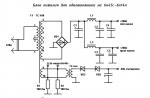
In the console (its diagram is shown in rice. one) an emitter-coupled generator is used in a two-stage amplifier, the frequency of harmonic oscillations of which is determined by the capacitance of the capacitor C1 and the measured inductance Lx connected to the spring terminals X1. Since the base of the transistor VT1 is directly connected to the collector VT2, the loop gain of the generator is high, which ensures stable generation when the L / C ratio changes over a wide range. The loop gain is proportional to the steepness of the transistors used and can be effectively controlled by changing the emitter current, for which a rectifier based on diodes VD1, VD2 and a control transistor VT3 are used. The introduction of an amplifier based on the VT4 transistor with КU= 8…9 made it possible to reduce the voltage amplitude on the circuit to the level of 80…90 mV with an output amplitude of 0.7 V. The emitter follower provides operation for a low-resistance load.

The device is operational when the supply voltage changes in the range of 5 ... 15 V, while the variations in the output voltage level do not exceed 20%, and the frequency drift is F = 168.5 kHz (with a high quality coil wound on a 50 VCh core with an inductance L = 35 µH) not more than 40 Hz!
In the design, transistors KT361B, KT361G, KT 3107 with any letter index can be used in positions VT1, VT2, although somewhat better results are achieved with KT326B; in position VT3 - silicon transistors of p-n-p structure, for example, KT209V, KT361B, KT361G, KT3107 with any letter index. For the buffer amplifier (VT4, VT5), most high-frequency transistors are suitable. The parameter h21Э for the transistor VT4 is more than 150, for the rest it is not less than 50.
Diodes VD, VD2 - any high-frequency silicon, for example, series KD503, KD509, KD521, KD522.
Resistors - MLT-0.125 or similar. Capacitors, except for C1, are small-sized, respectively, ceramic and electrolytic, let's say the spread is 1.5 ... 2 times.
Capacitor C1 with a capacity of 25330 pF determines the measurement accuracy, therefore it is advisable to select its value with a deviation of no more than ±1% (it can be made up of several thermostable capacitors, for example 10000 + 10000 + 5100 pF from the KSO, K31 group. If it is not possible to accurately select the capacitance, you can use the method described below.
It is convenient to use spring clips for "acoustic" cables as connector X1. Connector X3 for connection with a frequency meter - SR-50-73F.
Parts are mounted on a printed circuit board ( rice. 2) from one-sided foil fiberglass. It is permissible to use a wall-mounted installation. Any box of any material that is suitable in size can be used as a case for the attachment. It is necessary to place the X1 connector in such a way as to ensure the minimum length of the conductors connecting it to the board.

After checking the correct installation, apply 12 V power supply without connecting the coils to the X1 connector. The voltage at the emitter VT5 should be approximately equal to half the supply voltage; if the deviation is greater, the selection of the resistor R4 will be required. The current consumption will be close to 20 mA.
Connect an Lx coil with an inductance in the range of tens to hundreds of microhenries (the exact value is not critical) to connector X1, and an oscilloscope or a high-frequency voltmeter to connector X3. The output of the set-top box should have an alternating voltage of 0.45 ... 0.5 V eff (peak value 0.65 ... 0.7 V). If necessary, its level can be set in the range of 0.25 ... 0.7 Veff by selecting the resistor R8.
Now you can start calibrating the attachment by connecting it to the frequency meter. This can be done in several ways.
If it is possible to measure with an accuracy of at least 1% a coil on an open magnetic circuit with an inductance of the order of tens or hundreds of μH, then using it as a model, select the capacitance of the capacitors C1 ... C4 so that the readings of the attachment coincide with the required value.
In the second case, you will need one thermally stable reference capacitor, the capacitance of which is at least 1000 pF and is known with high accuracy. In the extreme case, if it is not possible to accurately measure the capacitance, capacitors KSO, K31 can be used with a tolerance of ± 2–5%, resigned to the probable increase in the error. The author used a K31-17 capacitor with a nominal capacitance of 5970 pF ± 0.5%. First, using the frequency meter, we fix the frequency F1 for the Lx coil without an additional external capacitor. Then we connect the reference capacitor Cet in parallel with the coil and fix the frequency F2. Now we can determine the real input capacitance of the assembled set-top box and the inductance of the coil Lx using the formulas
![]()
It takes a long time to manually do multiple recalculations, so the author uses the successful MIX10 calculation program, developed by A. Bespalchik and kindly posted by him on the TFR website < > .
In order to be able to use the simplified formulas given at the beginning of the article, it is necessary to set the capacitance Свх equal to 25330 ± 250 pF by selecting capacitors С1–С4. After the final adjustment of the capacitance by the capacitor C1, make a control measurement according to the above method to make sure that the capacitance Cin corresponds to the required one.
After that, the prefix is ready to work. Let's try to evaluate its capabilities; To do this, we will conduct several experiments.
1 . When measuring small inductance values, a large error is introduced by the set-top box's own inductance, which consists of the inductance of the conductors connecting the X1 connector to the board, and the mounting inductance. Let's try to measure it. First, we close the contacts of connector X1 with a straight short conductor. The twisted wires going to connector X1, 30 mm long, and the jumper, 30 mm long, form one turn of the coil. If there are KT326B transistors in the generator, oscillations occur only during shock excitation of the circuit by periodically turning on the power; in this case, the frequency F1 = 2.675 ... 2.73 MHz, which corresponds to an inductance of 0.14 μH (no generation occurs at all with KT3107B transistors). Now we will make a ring with a diameter of 3 from a wire with a diameter of 0.5 mm with a calculated inductance of about 0.08 μH and connect it to X1. For a generator based on KT326B transistors, the frequency meter showed a value of 2.310 MHz, which corresponds to an inductance of 0.19 μH. The variant on KT3107B transistors generated only with shock excitation of the circuit. Thus, the own inductance of the attachment turned out to be in the range of 0.1 ... 0.14 μH.
Conclusions: high measurement accuracy is provided for inductances over 5 µH. For values in the range of 0.5 ... 5 μH, it is necessary to take into account the intrinsic inductance of 0.1 ... 0.14 μH. With an inductance of less than 0.5 μH, the measurements are estimated. Confidently recorded minimum inductance value of 0.2 μH.
2 . Measurement of unknown inductance. Let's say for it the frequency F1 \u003d 0.16803 MHz, which, according to the simplified formula for calculating the inductance, gives 35.42 μH.
When checking with a reference capacitor, the frequency F2 = 0.15129 MHz corresponds to an inductance of 35.09 μH. The error is less than 1%.
3 . Using the measured inductance as a reference, you can estimate the input capacitance of the generator. The capacitance of the circuit consists of the capacitance of the capacitors C1–C4 and the capacitance Cgen, which consists of the sum of the mounting capacitance and the capacitance introduced by the transistors VT1, VT2, i.e. Cv = C1 + C gene.
To determine the C gene value, we turn off the capacitors C1–C4 and measure the frequency F3 with the inductance used. Now Cgen can be calculated by the formula
![]()
In the author's version of the attachment with KT3107B transistors, the capacitance Cgen is 85 pF, and with KT326B transistors it is 39 pF. Compared to the required value of 25330 pF, this is less than 0.4%, which allows the use of almost any high-frequency transistors without a noticeable effect on measurement accuracy.
4 . Due to the large self-capacitance of the attachment, when measuring inductance up to 0.1 H, the error introduced by the self-capacitance of the coils is insignificant. So, when measuring the inductance of the primary winding of the output transformer from transistor receivers, the value L = 105.6 mH was obtained. When the oscillatory circuit was supplemented with a reference capacitor of 5970 pF, another value was obtained - L = 102 mH, and the self-capacitance of the winding Str = Cmeas - C1 = 25822 - 25330 = 392 pF.
5 . The amplitude on the measuring oscillatory circuit of 70 ... 80 mV turns out to be less than the threshold for opening silicon p-n junctions, which in many cases makes it possible to measure the inductance of coils and transformers directly in the circuit (of course, de-energized). Due to the large self-capacitance of the attachment (25330 pF), if the capacitance in the measured circuit is not more than 1200 pF, the measurement error will not exceed 5%.
So, when measuring the inductance of the coil of the IF circuit (the circuit capacitance is not more than 1000 pF), a value of 92.1 μH was obtained directly on the transistor receiver board. When measuring the inductance of a coil soldered from the board, the calculated value turned out to be less - 88.7 μH (error less than 4%).
To connect to the inductors placed on the boards, the author uses probes with connecting wires 30 cm long, twisted in increments of one twist per centimeter. They introduce an additional inductance of 0.5 ... 0.6 μH - this is important to know when measuring small quantities, to evaluate it, it is enough to close the probes together.
In conclusion, a few more useful tips.
You can determine the magnetic permeability of an annular magnetic circuit without marking using the following method. Wind 10 turns of wire, evenly distributing it around the ring, and measure the inductance of the winding, and substitute the resulting inductance value into the formula:

![]()
L-inductance
W- number of turns
D,d,h - ring size in mm
In practical calculations, it is convenient to use a simplified formula for calculating the number of turns on ring magnetic circuits
The values of the coefficient k for a number of widespread ring magnetic circuits according to V. T. Polyakov are given in tab. one.
Table 1
|
Size |
К18х8х4 |
К18х8х4 |
К18х8х4 |
К18х8х4 |
К18х8х4 |
К18х8х4 |
|
Magnetic permeability |
3000 |
2000 |
1000 |
2000 |
1000 |
|
For widespread armored magnetic circuits made of carbonyl iron, it is more convenient to calculate the inductance in microhenry, so we introduce the coefficient m, and the formula will change accordingly.
![]()
Some values for common armored magnetic circuits are given in tab. 2.
|
Core |
SB-9a |
SB-12a |
SB-23-17a |
SB23-11a |
To compile a similar table for your existing ring and armored magnetic circuits, using the proposed prefix, will not be difficult.
LITERATURE
1.Hyduk P. The frequency meter measures the inductance. - Radio amateur, 1996, No. 6, p. 30. 2. L-meter with linear scale. - Radio, 1984, No. 5, p. 58, 61. 3. Poliakov V. Coils of inductance. - Radio, 2003, No. 1, p. 53.4. Poliakov V. Radio amateurs about the direct conversion technique. - M.: Patriot, 1990, p. 137, 138. 5. Semiconductor receiving-amplifying devices: Handbook of a radio amateur. / Tereshchuk R. M. and others / ― Kiev: Naukova Dumka, 1987, p. 104.
S. Belenetsky, Lugansk, Ukraine
Radio, 2005, No. 5, pp. 26-28