Capacitors. Now I will tell you in detail how to check it using an inexpensive and common measuring instrument - a multimeter, as well as how to use it with the appropriate function to find out the capacitance value.
Before checking the capacitor must be removed from the circuit, because without soldering it is almost impossible to do this due to the influence on the measurements of other components of the circuit. In most cases, without soldering from the circuit, you can only check with a multimeter only for a breakdown, in which there will be a short circuit at the capacitor terminals.
Some radio amateurs use the method to check on the board by charging - discharging the capacitor, changing the polarity by rearranging the ends of the multimeter or tester. Doubtful method, I once tried this method to use and I could not check anything, because there were many other capacitors in the circuit. I recommend that if an external examination failed to reveal anything, solder the capacitor for a correct check.
Remember that starting any work with capacitors- it is necessary to defuse his conclusions before this. To do this, I use a screwdriver with an insulated handle, which you need to hold to close the capacitor contacts. Powerful models in order to avoid spark damage to the metal part of the screwdriver, it is better to discharge with an incandescent bulb. It is necessary to hold on to the insulated part of the wires and touch the terminals of the capacitor. The lamp flashes and goes out, after which a full discharge will occur. But one bulb only needs to be discharged at an operating voltage of 220 Volts, for 380 Volts, use 2 bulbs connected in series.
How to check capacitors by external inspection
Before soldering from the circuit capacitor, inspect it externally. Very often, a visual malfunction is determined when inspecting electrolytic capacitors. 
If you find electrolyte smudges in the lower part and traces of corrosion (left picture) or swelling in the crosshair area on top (right picture), then such capacitors must be replaced.
Pretty simple in most cases, it is possible to check 220 volt capacitors using the following method:
- We check with a probe or a short circuit tester inside the capacitor.
- We charge capacitor from the mains with operating voltage in compliance with safety precautions.
- Disable it from the power supply.
- Shorting or we connect a light bulb, as described above - we saw a spark discharge or a flash in a light bulb, then the capacitor is in order.
How to test a capacitor with a multimeter
Capacitors are polar and non-polar. Only electrolytic ones are polar. They are soldered into the circuits only in compliance with the polarity to the positive positive contact, to the negative - negative contact. The minus opposite the contact is indicated by a tick on the golden or light longitudinal line on the capacitor case.
non-polar - no difference what contacts to connect or solder into the circuit.
Before starting the test don't forget to short the outputs. After that, we take the multimeter and switch it to mode.  A serviceable capacitor immediately after connection will start charging with direct current and the resistance on the display will be minimal (Figure 1). Further, the resistance will gradually increase until it reaches the maximum value or infinity (Figure 2).
In the event of a capacitor failure:
- When checking with a multimeter immediately infinity flashes. This indicates that a break has occurred inside the capacitor.
- The multimeter beeps and shows zero resistance - an insulator breakdown has occurred in the capacitor and a short circuit has occurred.
In both cases, the capacitors must be replaced.
Non-polar capacitors much easier to check. We set the resistance measurement limit on the Mega Ohm multimeter and touch the capacitor contacts with the measuring probes. A faulty capacitor will have a resistance of less than 2 Mega ohms.
You must consider that most tester models allow you to check only non-polar and polar capacitors with a rating of less than 0.25 uF for a short circuit.
How to determine the capacitance of a capacitor
All parameters are applied on the case of capacitors, to check the compliance of the capacitance or if this value cannot be read, it is necessary to use a multimeter with the “Cx” capacitance measurement function.
For measuring capacitance value, switch the multimeter to Cx mode with the expected maximum measurement limit for this capacitor. Some models have special sockets for testing small capacitors, into which contact legs are inserted according to the measurement limits. In others, measuring probes are used for this.
 The figure shows an example of measuring a capacitor at 9.5 microfarads, so the limit is set to 20 microfarads.
Do not forget Always discharge the capacitors before testing.
Related content:

It's been about a year and a half since I started doing electronics repairs on a regular basis. As it turned out, this is no less interesting than the design of electronic structures. Little by little people appeared who wanted, some from time to time, and some regularly, to cooperate with me as with a master. Due to the fact that the profitability of most of the repairs made does not allow renting a room, otherwise the rent eats up most of the profits, I work mainly at home or go out with tools to familiar individual entrepreneurs who buy consumer electronics and a workshop.
These are absolutely any circuits using stabilizers, DC-DC power converters, switching power supplies for any equipment, from computers to mobile chargers.

Swollen capacitor
Without this device, a significant part of the repairs performed by me either could not have been performed at all, or nevertheless were performed, but with great inconvenience in the form of constant soldering and soldering back electrolytic capacitors of small denomination, in order to measure the equivalent series resistance using a transistor tester. My own device allows you to measure this parameter without soldering the part, simply by touching the capacitor terminals with tweezers.
These capacitors with a nominal value of 0.33-22 uF, as you know, very rarely have notches in the upper part of the case, along which capacitors of a larger rating swell and open with a rosette, for example, familiar capacitors on motherboards and power supplies. The fact is that a capacitor that does not have these notches for releasing the excessive pressure that has formed, visually, without measuring with a device, even for an experienced electronics engineer, is indistinguishable from a fully working one.

Of course, if a home master has a one-time repair, for example, an ATX format computer power supply, it does not make sense to assemble this device, it is easier to immediately replace all low-value capacitors with new ones, but if you repair at least five power supplies every six months, this device is already desirable for you. assembly. What alternatives are there to assembling this meter? A purchased device worth about 2000 rubles, ESR micro.

ESR micro - photo
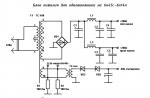
Of the differences and advantages of a purchased device, I can only name that its readings are displayed immediately in milliOhms, and my device needs to be converted from millivolts to milliohms. Which, however, does not cause difficulties, it is enough to calibrate the device according to the values \u200b\u200bof low-resistance precision resistors and compile a table for yourself. After working with the device for a couple of months, already visually, without any tables, just by looking at the multimeter display you already see the normal ESR value of the capacitor - on the verge or a replacement is already needed. The scheme of my device, by the way, was once taken from the Radio magazine.
Schematic diagram of the device

Initially, the device was assembled with self-made probes - tweezers with wide jaws, inconvenient when measuring on boards, with tight mounting. Then I looked at Ali express probes - tweezers for measuring SMD, connected to a multimeter. When ordering tweezers, the wire was mercilessly shortened so that the accuracy did not suffer greatly during the measurement, due to the length of the probe wires. Do not forget, there the bill goes to milliohms.

At first, my device was connected with probes to a multimeter and was made in the form of a prefix, but gradually I got tired of turning the multimeter knob each time, thereby developing a switching resource. Just then, a friend gave me a multimeter, due to the fact that I temporarily burned mine on an undischarged electrolytic capacitor. Subsequently, the device was restored, the resistors were soldered, and this multimeter, its connectors for connecting probes on the board were broken off, and jumpers were thrown by someone, but the measurement accuracy was no longer the same.

But for my purposes, an error of 1-2 percent did not solve anything and decided to make the device completely autonomous. To do this, I fastened the case of the multimeter and the case of the ESR meter with screws, and for greater convenience, switched the simultaneous switching on, the built-in multimeter and the ESR meter using a switch for two groups of contacts. The connections between the multimeter and the ESR meter, previously made with probes, were made with wires inside connected cases.

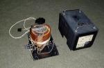
Capacitor tester - appearance
As practice has shown, the time to bring the device to combat readiness, and then, after measurements, turn it off, began to go significantly less, and, accordingly, the usability increased. Of the further improvements planned in this device is to transfer it to battery power, from a Li-ion battery from a phone, with the ability to recharge from the charge adapter board via the built-in Mini USB socket, from any charger from a smartphone with the ability to connect a USB cable.

As practice has shown, I have already converted it to battery power using a similar method, which, like the ESR meter, also has high consumption due to the graphic display installed in it. Feelings from the alteration were only positive. I've only charged once in six months. A step-up DC-DC converter was installed in the device, which turns 3.7 volts at the battery output into 9 volts, necessary for the operation of the device.

In this case, my device will have a double voltage conversion: first, from 3.7 volts to 9 volts, although I may also set the minimum voltage allowed for the input of the 7805 CV stabilizer to 7.5 volts, the device circuit is now powered from this stabilizer. The device itself, as you can see in the photo, is initially powered by a Krona battery, which, as you know, has a relatively small capacity.
The supply voltage of this microcircuit allows you to power it directly from 9 volts, but the fact is that as the battery discharges, I noticed that the readings during the measurement begin to slowly float away. To combat this, a 7805 stabilizer was installed, which, as you know, gives us a stable 5 volts at the output.

Also, due to the fact that the device often has to be carried with you in a diplomat, for repairs on the road, and there have already been cases of the switch turning on spontaneously, and, accordingly, the Kron battery was dropped to zero, what now, when this switch switches 2 power lines, a multimeter and the device itself, it would be more undesirable, since in this case, you will have to buy two crowns, worth 45 rubles.

It was decided to simply glue on the hot glue, along the edges of the switch, two self-tapping screws, from the cooler mount, in the computer power supply. The microcircuit used in the device is widespread and quite cheap, I purchased it at a cost of only about 15-20 rubles.

The whole device cost me, taking into account a free multimeter, probes - tweezers, costing 100 rubles, and the cost of parts for assembling the device, and a krone battery, it took about 150 rubles in total, in total everything you need cost a ridiculous amount of 250 rubles.

Tweezers for measuring capacitors on the board
That paid off already with the use of the device in repairs for a long time and many times. Of course, anyone who has the opportunity and desire to purchase an ESR micro can now say why I need these inconveniences, each time converting from millivolts to milliohms, although this is not required, as I wrote above, if on a purchased device I can immediately see , ready-made values.

Table of ESR values
The fact is that such devices incorporate a microcontroller, and during the measurement they are connected directly, relatively speaking, by the “port” of the microcontroller to the measured capacitor. What is highly undesirable, it is enough not to discharge the capacitor once after the circuit is de-energized before measurement, by closing its terminals with a metal object, such as a screwdriver, as we risk getting a non-working device.
The first version of probes

With its rather high cost, you see, it is not the best option. In my device, a 100 Ohm resistor is connected in parallel with the measured capacitor, which means that if the capacitor is still charged, it will start to discharge when the probes are connected. In the most extreme case, if the microcircuit used in my device burns out, you will only need to remove the microcircuit from the DIP socket and plug in a new one to make repairs.
Instrument upgrade

Everything, the repair of the device is over, you can take measurements again. And given the low cost of the microcircuit, this does not become a problem, it is enough just to purchase one or two microcircuits in reserve when purchasing parts for assembling this EPS meter.
Final version

In general, the device turned out to be simply chic and very convenient, and even if the parts for its assembly cost 2 times more, I would still safely recommend this EPS meter for assembly to all novice craftsmen who have a modest budget, or who want to save money and don't overpay. Good luck with your repairs! AKV.
Sometimes it becomes necessary to check electronic elements, including capacitors.
For a variety of reasons, capacitors fail, it can be an internal short circuit, an increase in leakage current, a breakdown of the capacitor due to exceeding the maximum allowable voltage, or the usual decrease in capacitance - a reason that over time comprehends almost all electrolytic capacitors.
The methods for checking the capacitor, we will consider, are quite simple, the main thing here is the ability to use a tester or multimeter and correctly apply these instructions.
First you need to know that all capacitors are divided into polar and non-polar. Electrolytic capacitors are polar, all the rest are non-polar.
The polar capacitors in the circuit should be placed in such a way that there is a minus supply on the indicated negative terminal, and a plus on the positive terminal, only this way.
If the polarity is reversed then at least this capacitor will fail, but with sufficient voltage it will swell and explode, so that in an emergency the capacitor does not break into fragments, in imported capacitors, in the upper part the case is made of thin material and special dividing slots are applied, with In an explosion, such a capacitor simply shoots up and does not touch the elements around it.
Checking Capacitors
The capacitor must be discharged before testing. any metal object by shorting its conclusions, and so before each test.
If the capacitor under test is located on the board, it is necessary to free at least one of its outputs from the circuit and then proceed to measurements. But since most modern capacitors have a fairly low fit, it is better to unsolder the capacitor completely.
Checking the capacitor with a multimeter
Using a multimeter, you can check almost any capacitor with a capacitance greater than 0.25 microfarads.
The polarity of the capacitor is indicated on the case in the form of a strip with minus signs - this is the negative terminal of the capacitor.
And so we set the tester to either continuity or resistance mode. The multimeter in this mode will have a constant voltage on its probes.
We touch the capacitor contacts with the probes and see how the resistance indicator increases smoothly - the capacitor is charging.
The charge rate will directly depend on the capacitance of the capacitor. After a certain time, the capacitor will be charged and the multimeter will display the value "1" or, in other words, "infinity", this already indicates that the capacitor is not broken and not closed.

But if, when the probes touch the capacitor contacts, we immediately observe the value "1", then this indicates an internal break - the capacitor is not working.
There is another, the value "000" or a close very small value that does not change (when charging), sometimes the multimeter beeps, this indicates a breakdown or short circuit of the plates inside the capacitor.
Non-polar capacitors they are checked quite simply, we set the tester to the resistance measurement mode (megaohms), touching the capacitor contacts with the probes - the resistance should be at least 2 Megohm. If less is observed, then the capacitor is faulty, but make sure that you did not touch the probes with your fingers at the time of measurement.
Checking capacitors with a pointer tester
Checking with a dial gauge. The essence of the test is the same as with a multimeter, but here you can already more clearly observe the process of charging the capacitor, because we see the deviations of the arrow and not the flashing numbers on the display. A serviceable capacitor in contact with the probes, do not forget to discharge, must first deflect the arrow and then slowly and smoothly return the arrow back, the return speed of the arrow will depend on the capacitance of the capacitor.
If the arrow does not deviate or deviates does not return, this indicates a clear malfunction of the capacitor.

But if the capacitance of the capacitor is very small, "charging" may not be noticed - almost immediately the arrow will go to infinity, that is, it will not budge. For a capacitor, more than 500 microfarads - such a picture will almost immediately indicate an internal break.
A good way would be to check a known good capacitor (for clarity) and compare with the test. This method will make it possible to more confidently answer the question - is the capacitor working?
AC voltage test
Since it is impossible to observe such a fast charging process for testing small capacitors there is a special method that will accurately determine whether there is a break in it.A small circuit is assembled consisting of a series-connected capacitor, an alternating current ammeter and a current-limiting resistor.
The connected circuit is connected to an alternating voltage source, with a voltage not exceeding 20% of the maximum voltage of the capacitor.
If the ammeter needle does not deviate, this indicates an internal break in the capacitor.
Checking the capacitance of the capacitor
To check the capacitance, we need to make sure that the real capacitance of the capacitor corresponds to that indicated on its case.All electrolytic capacitors eventually (during operation) "dry up" and lose their capacity, this is a natural process, and for each specific circuit there are allowances and deviations.
Check the capacitance with a multimeter in the "Cx" mode, select an approximate capacitance with a maximum limit.
The capacitor is discharged on a metal object, such as tweezers, and inserted into the capacitor test socket.
For more accurate readings, it is necessary to ensure that there is a new and not discharged "crown" in the multimeter.

They also use special devices that are outwardly similar to a multimeter, which are specialized specifically for testing capacitors and have a fairly wide range of capacitance measurements, from units of picofarads to tens of thousands of microfarads, not every professional multimeter can boast even half of that capacitance range.

But if you don’t have a multimeter or a “microfaradmeter” at hand, you can approximately measure the capacitance with an ohmmeter.
As it was written above, the capacitor is charged by touching the probes to its contacts - we "detect" the time the arrow deflected back and compare the time with a known good (new) capacitor, if the time does not differ much, then the capacitance is within normal limits and the capacitor is working.
In the same way, you can determine the leakage current of the capacitor. To do this, the capacitor is charged with probes until the arrow deflects back.
With an interval of several seconds (depending on the capacitance), the probes are applied again, if the arrow again makes the same all the way, then this indicates an increased leakage current and already a partial malfunction of the capacitor. In a serviceable capacitor, for several seconds, the larger the capacitance, the longer the time, the “charge” should remain and the arrow should no longer show such a low resistance at the beginning as during the first charge.
"Voltage charging".
This method of checking a similar situation is suitable for higher-voltage capacitors, since at low voltage (from the tester) the whole situation may not be clear.
And so the essence of the method lies in the fact that the capacitor is charged from a constant voltage source, for this the voltage is chosen slightly less than the maximum and the capacitor contacts are charged, usually 1-2 seconds is enough. After that, the "charging" is disconnected and the voltage at the capacitor's contacts is measured with a multimeter, it should be practically the same as that used when charging, if this is not the case and it is greatly underestimated, then the capacitor has a large leakage current and it is faulty.
The voltage is observed with a multimeter for some time, the capacitor will gradually lose voltage, the speed will depend on the capacitance and ESR (internal resistance).
How to check a capacitor without instruments?
In some situations, in the absence of an ohmmeter or voltmeter, the health of the electrolytic capacitor can only be checked if there is a source of suitable voltage. The capacitor is charged for 1-2 seconds, and then you need to close its contacts with a metal screwdriver.
A good capacitor should have a bright spark. If it is dim or barely noticeable, then this indicates that the capacitor is faulty and does not hold a charge well.
Capacitors- the most common components of electronic circuits after resistors. In addition, they are used in power electronics and electrical engineering devices: power supplies, electric motor starting circuits, in reactive power compensation installations. Therefore, it is not so rare to check the health of capacitors. Let's see how it's done.
Capacitors are divided into categories, which have their own characteristics when checking.
Consider the methods of testing each category separately.
Checking electrolytic capacitors
They are checked first appearance. Foreign barrel-shaped capacitors have a cruciform notch on top. Malfunctions of electrolytic capacitors are often accompanied by an increase in pressure inside the case. At the same time, domestic components can explode, staining everything around with the contents. The notch on imported capacitors avoids this. When the pressure rises, it swells and then bursts. If during the inspection elements with a swollen or damaged body are found, then their malfunction is beyond doubt.
For further verification, the capacitor will have to solder. It is impossible to check it as part of the scheme, since there will always be elements in it that distort the test results. The same applies to other categories of capacitors.
Before checking the health of the capacitor, it unload. To do this, close its conclusions to each other using tweezers, a piece of wire or another accessible metal object. High-capacity capacitors rated at 50 V or more that are used in power devices are best discharged in two stages. First - through the load (light bulb or resistor), then - by short-circuiting the leads. If the device they are part of has just been disconnected from the mains, then the element must be discharged before being soldered from the circuit and after that.

To check you will need multimeter or tester. In this case, the tester is preferable, since the movement of the arrow illustrates the process more clearly. The device is switched to a resistance measurement limit of at least 1 megohm. Please note that some instruments require an external power supply to operate at this limit.
When checking observe the polarity of the connection: we connect the positive terminal of the device to the terminal of the capacitor, marked with a “+” sign. Do not touch both probes of the instrument at the same time. This will measure the resistance of your body.
We touch the leads of the element under test with the probes. The check is that the measuring device will charge the capacitor with its battery. At the moment of the start of charging, the current is greatest, while the resistance of the element tends to zero. As it charges, the current drops and the resistance increases. When the capacitor is charged, the current through a healthy element is zero, and its resistance is infinity. With a leakage current through the capacitor, the resistance at the end of the charge differs from infinity. When closing between the plates, the device will show zero.
The larger the capacitance of the capacitor, the slower it charges. But in order to determine the capacity by the charge time, you need a wealth of experience gained by checking more than one hundred elements. And the loss of capacitance is one of the faults of capacitors. To measure it, you need a multimeter with the ability to measure capacitances. But these devices have a drawback: the upper limit of the measured capacitance is limited to 20 microfarads.

To measure capacitance over a wide range, LC meters or digital capacitance meters. They look like an ordinary multimeter, but they do not measure anything other than capacitance.

Not always the described methods help to determine the faulty element. Some faults only manifest themselves at operating voltage. on the capacitor plates, and all devices have a power supply of no more than 1.5 - 4.5 V. In such cases, only the installation of a known-good element will help instead of the one being tested.
Checking Non-Polar Fixed Capacitors
By charging the capacitor from a multimeter or tester, you can check the health of the elements whose capacitance not lower than 0.5 uF. The polarity of the connection does not matter. At lower values, you will not have time to notice changes in the readings of the device. In this case, only a digital capacitance meter will help. If the capacity of the tested element does not fit within the limits determined by its nominal value, taking into account the tolerance, then it is faulty. The multimeter can only show a pronounced short circuit between the plates.
Capacitors with an operating voltage of 400V and above can be tested by charging it from the network. In this case, the connection point must be protected from short circuit by a circuit breaker, and a resistor with a resistance of at least 100 ohms must be connected in series with the capacitor to limit the initial current surge. Immediately after charging and after some time, the voltage at the terminals of the element is measured, the charge must be maintained for a long time. Then it needs to be discharged, for which it is better to use the same resistor through which it was charged.
When soldering an element from the circuit, it inevitably heats up. Sometimes, at the same time, its performance is restored, so there is never a full guarantee that the soldered capacitor is in good condition after a successful check. If during troubleshooting you reach a dead end, try changing the elements to new ones one by one.
Features of testing capacitors with variable capacitance
The nominal value of the capacitance of variables and trimmer capacitors consists of two values - the minimum and maximum. Within these limits, the capacitance changes when adjusted. Therefore, it is necessary to check their serviceability by measuring with a digital capacitance meter at the extreme positions. In addition, it is worth looking at how the readings change when the regulator is moved from one extreme position to another. In the event of abrupt changes in the measured values or their disappearance, the capacitor is also rejected.
For variable capacitors, the absence of mechanical damage, the absence of rubbing and short circuits between the plates during movement is visually checked.
The cause of electrical breakdown is often the failure of the capacitor. To carry out repairs, you need to know how to check the capacitor with a multimeter. Of the tools, you will still need a soldering iron, since the part will have to be soldered from the board.
Polar capacitors are easy to check in ohmmeter mode. If the resistance of the part is infinitely large (one is on in the left corner), this means that a break has occurred.
Capacitor capacitance testing
An electrolytic capacitor dries out over time and its capacitance changes. To measure it, you need a special device. How to test an electrolytic capacitor with a multimeter? The device is connected to the part, and the required measurement limit is selected by the switch.

When an overload signal appears on the indicator, the tool switches to a lower accuracy. Similarly, the capacitance of non-polar capacitors is measured.
Types of capacitor faults
- The capacity has decreased due to drying out.
- Increased leakage current.
- Increased active losses in the circuit.
- Breakdown of insulation (short circuit of the plates).
- A break inside between the lining and the output.
Visual inspection of capacitors
Malfunctions occur due to mechanical damage, overheating, power surges, etc. Most often, a capacitor fails due to breakdown. It can be seen by the following defects: darkening, swelling or cracks. For domestic parts, when swollen, a small explosion may occur. Foreign capacitors are protected from it by a cross-shaped slot at the end of the part, where a slight swelling occurs, visible to the eye. A part with this malfunction may have a normal appearance, but be inoperative.
To check the element is unsoldered from the board, otherwise it is impossible to test it. The check can be done using the resistance map on the board, but for a specific model it is not always at hand, even during service.
Troubleshooting Non-Polar Capacitors
The resistance of a non-polar capacitor is measured. If it has a value of less than 2 mΩ, there is a malfunction (leakage or breakdown). A good part usually shows a resistance of more than 2 mΩ or infinity. When measuring, do not touch the probes with your hands, since the resistance of the body will be measured.
Breakdown testing can also be done in diode test mode.
A break in capacitors of small capacity cannot be detected by an indirect method. How to check the capacitance of a capacitor with a multimeter in a similar situation? Here you need a device where there is a necessary function.

Checking electrolytic capacitors
There are slight differences, how to check the capacitor with a multimeter in ohmmeter mode. Polar capacitors are checked in the same way, but their measurement threshold is 100 kOhm. As soon as the device is charged and the reading exceeds this value, it can be judged that the part is working.
Important! Before checking the performance of the capacitor with a multimeter, it should be discharged by connecting the leads. High-voltage parts from power supplies are connected to an active load, for example, through an incandescent lamp. If the charge is left, you can damage the device or get a noticeable discharge by touching the leads with your hands.
Probes are connected to the capacitor, showing an increase in resistance in a serviceable part. The black probe with negative polarity is connected to the negative conductor, and the red probe to the positive one. On the surface of an electrolytic capacitor, minus is indicated by a white stripe on the side.

On pointer instruments, it is more convenient to carry out such a check, since the capacitance value can be judged by the speed of movement of the pointer. You can test good parts with known values and compile a table that roughly determines the capacitance from the readings of the rate of voltage drop.
After the capacitor is charged during testing (usually up to 3 V), the voltage value is measured on it. If it is 1V or less, the part needs to be replaced because it is not charged. After checking, a working capacitor is soldered back, but it must first be discharged by shorting the legs with a probe.
The guarantee for an electrolytic capacitor means that for a given time, the value of its capacity will not go beyond the specified limits, usually not exceeding 20%. When the service life is exceeded, the part remains operational, but its capacitance value is different, and it must be controlled. How to check the capacitor with a multimeter in this case? Here, the capacitance is measured with a special device.
A break is difficult to detect with an ohmmeter. Its sign is the absence of a change in readings in the ohmmeter mode.
How to test a capacitor with a multimeter without soldering
The difficulty of checking the capacitor without dismantling lies in the fact that elements such as transformer windings or inductances, which have little direct current resistance, are adjacent to it. Measurements can be made in the usual way when there are no low-resistance parts nearby.

Conclusion
The home master should know how to check the capacitor with a multimeter. There are direct and indirect methods for this. Do not forget about the need to discharge the capacitor before each measurement.