MINISTRY OF TRANSPORT
RUSSIAN FEDERATION
MOSCOW STATE UNIVERSITY OF COMMUNICATIONS (MIIT)
B.V. Zhelenkov
BUILDING BASICS
LOGIC ELEMENTS
MOSCOW-2003
Ministry of Railways of the Russian Federation
Moscow State University of Railways
messages (MIIT)
Department of "Electronic Computers"
B.V. Zhelenkov
Approved
editorial and publishing
university council
BUILDING BASICS
LOGIC ELEMENTS
Guidelines for laboratory work
discipline "Computer circuitry"
For 3rd year students
Specialties 220100, 552800
Moscow-2003
UDC 681.3
Zhelenkov B.V. Fundamentals of constructing logical elements. Guidelines for laboratory work on the discipline "Computer circuitry" - M .: MIIT, 2003.-82s.
The guidelines are intended for third-year students of the specialty "Computers, complexes, systems and networks" and are necessary for performing laboratory work and UIRS in the discipline "Computer circuitry". The necessary information for preparing for work, a description of the equipment, the order of execution, options for tasks, an example of laboratory work and a list of necessary literature are provided.
These guidelines are compiled on the basis of the materials of the guidelines: "Study of measuring, recording and research equipment", "Study of the first type logical signal shaper", "Study of the second type logical signal shaper", "Research of TTL circuits", "Research of CMOS circuits" by the authors Gramolina V.V. and Urusova A.V.
© Moscow State University of Railway Engineering (MIIT), 2003
Educational and methodical edition
Zhelenkov Boris Vladimirovich
BUILDING BASICS
LOGIC ELEMENTS
Guidelines for laboratory work
discipline "Computer circuitry"
127994 Moscow, st. Obraztsova, 15
Printing house of MIIT
DESCRIPTION OF EQUIPMENT FOR
PERFORMANCE OF LABORATORY WORKS.
Technical data and rules
Work with the oscilloscope S1-67
Using the S1-67 oscilloscope, you can observe periodic signals in the frequency range of 5 Hz - 10 MHz with an amplitude of 5 mV to 140V. Using the S1-67 oscilloscope, you can accurately measure time intervals from 0.1 ms to 0.2 s. The pulse edge measurement accuracy is guaranteed when the rise time is greater than 30ns. With shorter rise times, the measurement error increases.
1.1.1. Controls and their purpose
The main controls of the C1-67 oscilloscope are shown in fig. 1.1.
Toggle switch "NETWORK" - is used to turn on the device.
Handle "BRIGHTNESS" - serves to set the required brightness of the beam.
PIP "FOCUS" - serves to focus the beam.
Handle "SCALE" - serves to adjust the illumination of the scale.
Amplifier
The input jack "1MOm 40pF" is used to supply the signal under study to the input of the oscilloscope.
The input switch has three positions to select one of the following inputs:
position "≈" - the so-called "potential input", i.e. the entire signal under study (both variable and constant components) will be fed to the input of the vertical deflection amplifier. This provision is the most used;
position "~" - the so-called "capacitive input", i.e. only the variable component of the signal under study is fed to the input of the vertical deflection amplifier;
“^” position - in this case, the amplifier input is disconnected from the input jack and grounded. The position is used to determine the zero level for amplitude measurements.
Rice. 1.1. The front panel of the oscilloscope C1-67:
1 - oscilloscope input; 2 - input of an external signal that synchronizes the sweep.
The "GAIN" knob is used to set the value of the division of the vertical scale. This handle is structurally made in the form of two handles on the same axis. The handle, which has a larger diameter and is located closer to the instrument panel, switches the amplitude ranges ("VOLTS / DIV"). The grid cell of the screen is taken as the division of the scale. The smaller diameter knob smoothly changes the gain. To accurately set the required division price, you need to turn the smooth amplification knob to the right (clockwise) until it stops, and then use the range switch to select the division price according to the scale printed on the instrument panel. It must be remembered that the value of the division of the vertical scale is equal to the set value only if the central knob of smooth amplification is in the extreme right position (in which it is fixed).
The "b" knob is used to move the beam vertically. With this knob, you can set the zero level, for example, in the center of the screen. To do this, the input must be set to the "^" position. .
Scan
Handles "SMOOTH", "COARSE" are used to move the beginning of the beam sweep horizontally.
The DURATION knob is used to set the value of the division of the horizontal scale. This handle is structurally made in the form of two handles on the same axis. The handle, which has a larger diameter and is located closer to the instrument panel, switches the sweep duration range (“TIME / DIV”). A smaller diameter knob smoothly changes the duration of the sweep. To accurately set the required division value, you need to turn the smooth adjustment knob to the right (clockwise) until it stops, and then select the division value using the switch according to the scale printed on the instrument panel. It must always be remembered that the division value of the horizontal scale is equal to the set value only if the smooth adjustment knob is in the extreme right position (in which it is fixed).
The sweep multiplier switch has two positions:
"x1" - the division price is precisely determined by the sweep duration switch;
"x0.2" - the division price is reduced by 5 times, while the timing diagram is stretched relative to the center of the screen.
For ease of setting the division price, the toggle switch is most often in the “x1” position. And only if the measured interval occupies few divisions even with the extreme right position of the switch, then in this case the toggle switch is brought to the “x0.2” position.
The STAB knob is used to select the operating mode of the sweep generator (waiting, self-oscillating).
Synchronization
The switch for the type of synchronization, having the positions "INSIDE" and "EXTERNAL", is used to set the internal or external synchronization, respectively. In the case of external synchronization, the switch has two positions: "1:1" and "1:10".
In the "1:10" position, the external trigger signal is attenuated by a factor of 10.
The “≈, ~, +, -” switch triggers the sweep on the rising (+) or falling (-) of an external trigger signal, and also allows you to select potential (≈) or capacitive (~) input for this signal.
The "LEVEL" knob is used to bind the start of the sweep to a certain level of the external clock signal.
The “SYNC” jack is used to supply an external trigger signal (sync signal), used in the external synchronization mode.
Turning on and setting up the oscilloscope
1. Turn on the device with the "NETWORK" toggle switch and warm it up for 1 - 2 minutes.
2. Use the “≈,┴, ~” switch to ground the input of the amplifier.
3. If there is no beam on the screen:
move to the extreme right position (clockwise) the "STAB" and "BRIGHTNESS" knobs; use the handles "↔" and "↕" to find the beam and move it to the working area of the screen.
4. Use the FOCUS and BRIGHTNESS knobs to adjust the beam.
5. Use the “↕” knob to move the beam to the central axis of the screen; in the general case, it is taken as the zero level.
6. Set the input switch to the potential input ≈ (it can be used in the vast majority of cases) and apply the test signal to the input of the oscilloscope (jack "1MOm 40pF").
7. Set the required division price on the vertical (gain) and horizontal (scan) scales.
8. To obtain a stable "picture", it is necessary to use a waiting sweep, and to study the relative temporal location of various signals - external synchronization.
This mode is the most convenient and frequently used. To obtain this mode, you must:
apply an external trigger signal to the “SYNCHR” socket;
switch "INT. EXT” set to the position “EXT 1:1”;
turn the "LEVEL" knob to the extreme left position;
turn the STAB knob to the left until the image breaks on the screen (5-10° to the left of the break point);
turn the "LEVEL" knob to achieve a stable image. If this does not work out, then you should slightly turn the “STAB” knob to the right and use the “LEVEL” knob to achieve full image stability.
Types of oscilloscope adjustments
Consider the front panel of the two-channel oscilloscope C1-83 (see Fig. 16).
Figure 16: Front panel of the C1-83 oscilloscope.
A - channel I control.
B - channel display control.
B - channel control II.
G - adjustment of the brightness of the beam, focusing and backlighting of the screen.
D - sweep control.
E - synchronization control.
It is clearly seen that the oscilloscope screen is divided into cells. These cells are called divisions and are used in measurements: all vertical and horizontal scales are attached to them. The vertical scale is volts per division (V/div or V/div), the horizontal scale is seconds (milli- and microseconds) per division. Typically, the oscilloscope has 6 ... 10 horizontal divisions and 4 ... 8 vertical divisions. The central vertical and horizontal lines have additional risks dividing the division into 5 or 10 parts (see Fig. 17). Risks serve for more precise measurements, they are fractions of a division.

Figure 17: Oscilloscope screen divisions
The controls for both channels are the same. Consider it using the example of channel I (see Fig. 18)

Figure 18: Channel I controls.
1. Input mode switch. In the upper position “ ”, both direct and alternating voltage are supplied to the input. This is called "open input" - that is, open to DC. In the lower “~” position, only AC voltage passes to the input, this allows you to measure a small AC voltage against a large DC voltage, for example, in amplifiers. This is implemented very simply: the input of the amplifier is connected through a capacitor. This is called "closed entrance". It should be noted that when the input is closed, very low frequencies (below 1 ... 5 Hz) are greatly attenuated, so they can only be measured when the input is open. In the middle position of switch 1, the oscilloscope amplifier input is disconnected from the input connector and shorted to ground. This allows using knob 7 to set the scan line to the right place.
2. Channel input connector.
3, 4, 5, 6. Vertical deflection channel sensitivity control (vertical scale). Switch 4 sets the scale in steps. The values it sets are marked next to it. The selected value is indicated by notch 5 on the switch. In the figure, it indicates a value of 0.2 volts / division. Handle 3, located correspondingly with the switch, allows you to smoothly reduce the scale by 2...3 times. In the extreme right position (in Fig. 18 the knob is “smoothly” exactly in it), this knob has a fixation, then the vertical scale is exactly equal to that set by switch 4. The scale values highlighted by bracket 6 are indicated in millivolts per division - this is indicated by the inscription "mV" inside the bracket.
7. The handle has two functions. When rotated, it moves the channel chart vertically up or down. When “pulling out”, it sets the vertical scale multiplier: the extended handle (see Fig. 19) sets the x1 multiplier, and the recessed multiplier x10. The recessed and extended positions are symbolically shown above and below the handle.

Figure 19: The vertical scale multiplier knob is pulled out to the "x1" position
Channel II (see fig. 20) is similar to channel I:

Figure 20: Channel II controls
But the second channel has an additional switch 6 that allows you to invert its input signal. In the pressed position, the channel works as usual, and in the extended position it is inverted, that is, with a negative input signal, the beam moves up, and with a positive input, it moves down. This is necessary when measuring, for example, phase shift.
On fig. 21 shows the channel display control, which is determined by pressing one of the buttons.

Figure 21: Channel Display Control
1 - Only channel I works, channel II is disabled.
2 - Both channels are displayed simultaneously (the beam switches between channels very quickly) and the mutual position of the waveforms of both channels is correct. In this mode, phase shift can be measured.
3 - The oscilloscope shows the sum or difference of the signals in the channels (the sign of the second channel is determined by the position of the knob 6 in Fig. 20).
4 - The signals of both channels are displayed, but they are independent in time, so no comparison of the signals with respect to time and phase shift can be made.
5 - Only channel II works, channel I is disabled.

Figure 22: Sweep controls
The sweep control panel (see Figure 22) is similar to the vertical deflection channel control panel. It contains a knob 4 that allows you to shift the image left-right and a combined regulator (1 - steps, 3 - smoothly) of the sweep speed (horizontal scale). Notch 2 on the switch indicates the set value. As with the vertical channels, the sweep rate switch has different units: seconds s, milliseconds ms, microseconds µs. Extended/recessed knob 4 sets the sweep speed multiplier x0.2 and x1, respectively.

Figure 23: Synchronization controls
On the synchronization control panel (see Fig. 23) you can set:
1 - Source of internal synchronization: the voltage of which channel synchronizes the movement of the beam. This synchronization is produced by the input signal, therefore it is called internal. This mode is used for most measurements. The options here are: either synchronization only with the signal of channel I. Or an attempt to synchronize from channel I, and if it does not work, then synchronization is performed by the signal of channel II. The first option sometimes works a little better, so you need to try to get the signal of the first channel to be large enough for stable synchronization. In the vast majority of cases, for normal operation, this particular synchronization mode should be selected by turning on the “I” button.
2 - External synchronization. The motion of the beam is synchronized by pulses supplied from a special external source to the synchronization input of the oscilloscope. This mode is sometimes required to study specific signals.
If there is no external synchronization source, then it is impossible to obtain a stable image. Buttons "0.5-5" and "5-50" set the range of input voltages from an external synchronization source. The "X-Y" button, together with the "II X-Y" button for controlling the display of channels (see Fig. 21), sends a channel II signal to the horizontal scanning plates. In this mode, you can observe the Lissajous figures.
3 - "Sync Level" knob. Sets the clock voltage. In the depressed position of this knob, the sweep is automatic. In this case, the movement of the beam will occur even if synchronization does not occur. The beam is delayed at the beginning of the movement for some time until the moment of synchronization, but after a while it still starts moving. This is a "soft" mode, more comfortable to work with, as the beam always remains visible. In the extended position of the handle, the waiting sweep is turned on. In this mode, the beam will not start moving until synchronization occurs. If synchronization does not occur, the beam is not moving. This mode is well suited for observing non-periodic signals.
4 - "Polarity" of synchronization. In fact, the signs "+" and "-" mean something else. In the “+” position, synchronization occurs along the front, i.e. at the moment when the input voltage reaches the set value (with the “Synchronization level” knob) when the input voltage increases (changes from “-” to “+”), fig. 24. In the "-" position, synchronization occurs on a decline - when the input voltage decreases (changes from "+" to "-"). In the oscilloscope, two different circuits are used in the synchronization circuit: one determines whether the input voltage is equal to the specified one, and if it is, it starts the movement of the beam. This voltage is set by the Sync Level knob. The second circuit determines how the input voltage changes - increases or decreases. And accordingly allows the first scheme to work.

Figure 24: Synchronization "polarity".
5 - Synchronization input mode. Applies to both external and internal synchronization. In the "~" position, the input is closed, and synchronization occurs only from alternating voltage. In the position, the input is open, and both alternating voltage and constant voltage act on the operation of the synchronization circuit. The LF mode is the same, but the signal enters the synchronization circuit through a low-pass filter that cuts off high-frequency noise. This mode is not available on all oscilloscopes.
6 - Input for external synchronization signal.
Comparative characteristics of oscilloscopes S1-67 and S1-102M

Figure 25: Oscilloscope C1-67

Figure 26: Oscilloscope S1-102M
Table 1: Comparative characteristics of oscilloscopes
|
Number of beams (channels) CRT |
|
|
two-channel |
single channel |
|
Range of measured voltages |
|
|
28 mV - 140 V |
28 mV - 200 V |
|
Range of measured time intervals |
|
|
0.4 µs - 0.2 s |
0.2 µs - 0.2 s |
|
Bandwidth |
|
|
Rise time |
|
|
Signal amplitude measurement error |
|
|
Not more than 5% |
Not more than 5% |
|
Measurement error of time intervals |
|
|
Not more than 5% |
Not more than 5% |
|
Release on PH |
|
|
Not more than 3% |
No more than 10% |
|
Beam line width |
|
|
Horizontal screen area |
|
|
Supply voltage |
|
|
220 V, 50 Hz; 115 V, 400 Hz |
220 V, 50 Hz; 115 V, 400 Hz |
|
Power consumption |
|
|
Operating temperature range |
|
|
Y channel parameters |
|
|
Channel 1 and 2 sensitivity |
|
|
5 mV/div - 10 V/div |
10 mV/div - 20 mV/div |
|
Channel input impedance |
|
|
Channel input capacitance |
|
|
Channel parameters X |
|
|
Minimum sweep duration |
|
|
0.1 µs/div |
0.1 µs/div |
|
Sweep duration maximum |
|
|
20 ms/div |
|
|
External clock amplitude |
|
|
External sync frequency range |
|
|
3 Hz - 50 MHz |
5 Hz - 10 MHz |
|
External sync input impedance |
|
|
Channel Z parameters |
|
|
Channel frequency range |
|
|
1 Hz - 50 MHz |
20 Hz - 2 MHz |
|
Input voltage range |
|
|
Channel input impedance |
|
|
Calibration channel parameters |
|
|
Calibration signal frequency Square wave |
|
|
Calibration signal voltage |
|
|
0.06 or 0.6 V |
Conclusion
Based on the data I have given, I will describe and review the S1-65A oscilloscope, as it is used at the Kola Nuclear Power Plant in the Thermal Automation and Measurements workshop.
From 08/10/2019 to 09/07/2019 technical break.
We will resume receiving parcels from 09/08/2019.
Buying an oscilloscope C1-67, prices and content of precious metals
The company Radiodetali Plus has been operating since 03.2012. During this time we have accumulated a solid store of knowledge and experience in running this business. More than 90% of radio components have been thoroughly studied by us.
Of course, not all the details and elements are familiar to us, and it’s impossible to know everything, since new samples are constantly appearing for study, but we accept the details that we have studied and entered into our photo catalog on an ongoing basis.
We also buy Soviet-made measuring instruments. Imported devices have been little studied, but they contain few radio components containing precious metals. In any case, each new device that we have not studied is interesting.
This page presents containing precious metals in radio components that are on boards inside the device. Oscilloscope price C1-67 is the most important factor by which our customers are guided by the sale of this device. We will be able to give a higher purchase price oscilloscope S1-67 than our competitors, has already been verified by customers who come to our radio components reception point.
| the name of detail | Qty |
|---|---|
| Capacitors KM green common group H90 | 9.6 g |
| Capacitors KM red group 1MO with release date | 1.6 g |
| Capacitors KM red group 2M2 with release date | 2.2 g |
| Capacitors KM green group H30 | 7.9 g |
| KT 201 transistors with yellow leads | 5 pieces. |
| KT 306 transistors with yellow leads | 19 pcs. |
| Transistors KT 3102 in a white case | 9 pcs. |
| Transistor KT 602 in a white case | 6 pcs. |
| Transistor KT 608 in a white case | 1 PC. |
| Transistor KT 608 with yellow leads | 1 PC. |
| Resistors SP5-1 VA | 2 pcs. |
| Resistor PP3-43 with the sign "rhombus" | 1 PC. |
Attention!!! Delivery of ALL devices that are listed on the site takes place throughout the territory of the following countries: Russian Federation, Ukraine, Republic of Belarus, Republic of Kazakhstan and other CIS countries.
In Russia, there is an established delivery system to such cities: Moscow, St. Petersburg, Surgut, Nizhnevartovsk, Omsk, Perm, Ufa, Norilsk, Chelyabinsk, Novokuznetsk, Cherepovets, Almetyevsk, Volgograd, Lipetsk Magnitogorsk, Togliatti, Kogalym, Kstovo, Novy Urengoy, Nizhnekamsk, Nefteyugansk, Nizhny Tagil, Khanty-Mansiysk, Yekaterinburg, Samara, Kaliningrad, Nadym, Noyabrsk, Vyksa, Nizhny Novgorod, Kaluga, Novosibirsk, Rostov-on-Don, Verkhnyaya Pyshma, Krasnoyarsk, Kazan, Naberezhnye Chelny, Murmansk, Vsevolozhsk, Yaroslavl, Kemerovo, Ryazan, Saratov, Tula, Usinsk, Orenburg, Novotroitsk, Krasnodar, Ulyanovsk, Izhevsk, Irkutsk, Tyumen, Voronezh, Cheboksary, Neftekamsk, Veliky Novgorod, Tver, Astrakhan, Novomoskovsk, Tomsk, Prokopyevsk, Penza, Uray, Pervouralsk , Belgorod, Kursk, Taganrog, Vladimir, Neftegorsk, Kirov, Bryansk, Smolensk, Saransk, Ulan-Ude, Vladivostok, Vorkuta, Podolsk, Krasnogorsk, Novouralsk, Novorossiysk, Khabarovsk, Zheleznogorsk, Kostroma, Zelenogorsk, Tambov, Stavropol, Svetogorsk, Zhigulevsk, Arkhangelsk and other cities of the Russian Federation.
In Ukraine, there is an established delivery system to such cities: Kiev, Kharkov, Dnipro (Dnepropetrovsk), Odessa, Donetsk, Lviv, Zaporozhye, Nikolaev, Luhansk, Vinnitsa, Simferopol, Kherson, Poltava, Chernihiv, Cherkasy, Sumy, Zhytomyr, Kirovograd, Khmelnitsky , Rivne, Chernivtsi, Ternopil, Ivano-Frankivsk, Lutsk, Uzhgorod and other cities of Ukraine.
In Belarus, there is an established delivery system to such cities: Minsk, Vitebsk, Mogilev, Gomel, Mozyr, Brest, Lida, Pinsk, Orsha, Polotsk, Grodno, Zhodino, Molodechno and other cities of the Republic of Belarus.
In Kazakhstan, there is an established delivery system to such cities: Astana, Almaty, Ekibastuz, Pavlodar, Aktobe, Karaganda, Uralsk, Aktau, Atyrau, Arkalyk, Balkhash, Zhezkazgan, Kokshetau, Kostanay, Taraz, Shymkent, Kyzylorda, Lisakovsk, Shakhtinsk, Petropavlovsk, Rieder, Rudny, Semey, Taldykorgan, Temirtau, Ust-Kamenogorsk and other cities of the Republic of Kazakhstan.
Manufacturer TM "Infrakar" is a manufacturer of multifunctional devices such as a gas analyzer and smoke meter.
If the website does not contain the information you need about the device in the technical description, you can always contact us for help. Our qualified managers will clarify for you the technical characteristics of the device from its technical documentation: operating instructions, passport, form, operating manual, diagrams. If necessary, we will take photos of the device, stand or device you are interested in.
You can leave feedback on the device, meter, device, indicator or product purchased from us. Your review, with your consent, will be published on the site without specifying contact information.
The description for the devices is taken from the technical documentation or from the technical literature. Most of the product photos are taken directly by our specialists before the goods are shipped. The description of the device provides the main technical characteristics of the devices: nominal value, measurement range, accuracy class, scale, supply voltage, dimensions (size), weight. If on the site you see a discrepancy between the name of the device (model) and the technical characteristics, photo or attached documents - let us know - you will receive a useful gift along with the purchased device.
If necessary, you can specify the total weight and dimensions or the size of a separate part of the meter in our service center. If necessary, our engineers will help you choose a complete analogue or the most suitable replacement for the device you are interested in. All analogues and replacements will be tested in one of our laboratories for full compliance with your requirements.
Our company carries out repair and maintenance of measuring equipment for more than 75 different manufacturing plants of the former USSR and the CIS. We also carry out such metrological procedures: calibration, taring, graduation, testing of measuring equipment.
Devices are delivered to the following countries: Azerbaijan (Baku), Armenia (Yerevan), Kyrgyzstan (Bishkek), Moldova (Chisinau), Tajikistan (Dushanbe), Turkmenistan (Ashgabat), Uzbekistan (Tashkent), Lithuania (Vilnius), Latvia (Riga) ), Estonia (Tallinn), Georgia (Tbilisi).
Zapadpribor LLC is a huge selection of measuring equipment at the best price-quality ratio. So that you can buy devices inexpensively, we monitor competitors' prices and are always ready to offer a lower price. We only sell quality products at the best prices. On our website you can buy cheap both the latest innovations and time-tested devices from the best manufacturers.
The site constantly operates the action "I will buy at the best price" - if on another Internet resource the product presented on our site has a lower price, then we will sell it to you even cheaper! Buyers also receive an additional discount for leaving a review or photos of the use of our products.
The price list does not contain all the range of products offered. Prices for goods not included in the price list can be found by contacting managers. Also, from our managers you can get detailed information on how to buy measuring instruments wholesale and retail at a cheap and profitable price. Phone and e-mail for consultations on purchase, delivery or receiving a discount are given above the product description. We have the most qualified employees, high-quality equipment and a favorable price.
Zapadpribor LLC is an official dealer of measuring equipment manufacturers. Our goal is to sell high quality products with the best price and service to our customers. Our company can not only sell the device you need, but also offer additional services for its verification, repair and installation. To make you have a pleasant experience after buying on our website, we have provided special guaranteed gifts for the most popular products.
The META plant is a manufacturer of the most reliable technical inspection devices. The STM brake tester is produced at this plant.
If you can repair the device yourself, then our engineers can provide you with a complete set of necessary technical documentation: electrical diagram, TO, RE, FO, PS. We also have an extensive database of technical and metrological documents: technical specifications (TU), terms of reference (TOR), GOST, industry standard (OST), verification methodology, certification methodology, verification scheme for more than 3500 types of measuring equipment from the manufacturer of this equipment. From the site you can download all the necessary software (program, driver) necessary for the operation of the purchased device.
We also have a library of legal documents that are related to our field of activity: law, code, resolution, decree, temporary situation.
At the request of the customer, verification or metrological certification is provided for each measuring device. Our employees can represent your interests in such metrological organizations as Rostest (Rosstandart), Gosstandart, Gospotrebstandart, TsLIT, OGMetr.
Sometimes customers may enter the name of our company incorrectly - for example, zapadpribor, zapadprylad, zapadpribor, zapadprilad, zakhіdpribor, zakhіdpribor, zahidpribor, zahidprilad, zahidprіbor, zahidprybor, zahidprylad. That's right - zapadpribor.
Zapadpribor LLC is a supplier of ammeters, voltmeters, wattmeters, frequency meters, phase meters, shunts and other devices from such measuring equipment manufacturers as: PO Elektrotochpribor (M2044, M2051), Omsk; JSC Instrument-Making Plant Vibrator (M1611, Ts1611), St. Petersburg; Krasnodar ZIP OJSC (E365, E377, E378), ZIP-Partner LLC (Ts301, Ts302, Ts300) and ZIP Yurimov LLC (M381, Ts33), Krasnodar; OJSC "VZEP" ("Vitebsk plant of electrical measuring instruments") (E8030, E8021), Vitebsk; JSC Elektropribor (M42300, M42301, M42303, M42304, M42305, M42306), Cheboksary; JSC "Elektroizmeritel" (Ts4342, Ts4352, Ts4353) Zhytomyr; PJSC "Uman Plant" Megommetr "(F4102, F4103, F4104, M4100), Uman.
The device (Fig. 6-4) is designed to observe electrical signals and measure their amplitude and time parameters.
Main technical characteristics
The range of measured voltages is 28 mV ... 200 V.
The range of measured time intervals is 0.2 ms.0.2 s.
The working area of the screen has 7 vertical divisions and 10 horizontal divisions (1 division = 0.6 cm). The width of the beam line on the screen is -0.6 mm.
The minimum sweep repetition rate when observing the fastest process is 400 Hz.
Bandwidth of the channel of vertical deflection of the beam with uneven amplitude-frequency characteristics of 3 dB - 0...10 MHz; transient response rise time - 35 ns; overshoot on the transient response -10% with a pulse with a front duration of 35 ns (absent with a pulse with a front duration of more than 100 ns); calibrated deviation factor within 10 mV/div ... 20 V/div is set in steps 1, 2, 5 and smoothly with overlap 1: 2, 5; input impedance - 1 MΩ ± 20 kΩ (10 ± 1 MΩ with remote divider 1:10); drop of the peak of the transient response - 10% with a closed input; the maximum allowable total signal voltage at the closed input is 300 V.
The calibrated sweep factor of the horizontal deflection channel of the beam is 0.1 µs/div... 20 ms/div (set in steps of 1, 2, 5, stretch multipliers -1 and 0.1).
Internal synchronization is carried out by signals with a vertical image size of more than 3 mm in the frequency range of 5 Hz ... 10 MHz and pulses with a duration of more than 0.1 μs; external synchronization - by signals with an amplitude of 0.5 ... 20 V in the frequency range of 5 Hz ... 10 MHz.
Rectangular pulses of the calibration signals of the deviation and sweep coefficients follow with a frequency of 2000 Hz, their amplitudes are 0.06 and 0.6 V; amplitude and frequency setting error - ±2%.
9. Bandwidth of the horizontal beam deflection channel in X-Y mode -0...2 MHz, deflection coefficient - 1 V/div.
Input impedance of channel Z - 10 kOhm; input voltage - 2...60 V; bandwidth - 20 Hz ... 2 MHz; measurement errors: amplitudes of pulse signals with a duration of more than 0.1 μs in the range of 40 mV ... 140 V - ± 5%, amplitudes of sinusoidal signals in the frequency range of 0 ... 2 MHz - ± 10%, additional (remote divider 1: 10 ) - ± 10%, time intervals in the range of 0.2 ... 0.4 µs - no more than ± 5% (± 10% using stretching).
The device is powered from an AC voltage of 220 ± 22 V with a frequency of 50 ± 0.5 Hz or a voltage of 115 ± 5.5 V with a frequency of 400 Hz or from a DC voltage source of 24 ± 2.4 V.
Power consumption from the AC voltage network - 45 V. A (from the DC voltage source, the current consumption is 1.1 A).
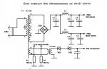
Device diagram
(Fig. 6-6). Using the input attenuator, which is a compensated voltage divider, the signal amplitude is set, convenient for observation and research on the screen of the cathode ray tube. In the vertical deflection channel of the beam, the signal is amplified to the required amplitude before entering the vertically deflecting plates of the tube. To be able to explore and observe the leading edge of short pulses, the channel has a delay line.
The trigger and trigger circuit generates constant-amplitude rectangular pulses, regardless of the amplitude and shape of the incoming signal. This achieves a stable start-up of the sweep generator, which produces a sawtooth voltage. The latter is amplified to the required value in the horizontal deflection channel and enters the deflecting plates of the tube. The device provides for the possibility of supplying an external signal to the sweep amplifier when it arrives at socket X; in this case, the sweep amplifier is disconnected from the generator.
From the vertical deflection channel to the delay line, the signal under study is fed to the input of the synchronization and sweep trigger circuit. An external signal connected to the SYNC input jack can be used for triggering.
The beam control circuit generates rectangular pulses that are fed to special blanking plates and extinguish the beam during the reverse sweep.

The Calibrator generates rectangular pulses used to calibrate the vertical deflection channel gain, offset compensation, and to calibrate the sweep duration.
The oscilloscope provides the ability to obtain brightness marks when an external signal is applied to the Z sockets.
The power supply provides power to the entire device.
The input attenuator is a frequency-compensated voltage divider having 11 division steps with division factors of 1, 2, 5, 10, 20, 50, 100, 200, 500, 1000 and 2000. In the first three positions of the attenuator (0.01; 0 0.02; 0.05) the division factor is adjusted by stepwise change in the gain of the amplifier, in other positions - by dividing the input signal by dividers made on passive elements R, C. The resistance of the precision resistors of the input attenuator is selected in such a way as to provide the same input impedance regardless of the position of the voltage divider VOLT/DIV. Variable capacitors C9, SP, C18, C19 are used to compensate for the characteristics of the attenuator in the entire frequency band. Capacitor C15 is designed for frequency compensation of the characteristics of the divider when two of its links are connected in series. With the help of an external divider (1:10), the total division ratio of the input attenuator is increased by 10 times.
To ensure a large input resistance and a small input capacitance of the vertical beam deflection channel, as well as a small temperature drift of the amplifier, the input stage of the preamplifier (board U1) is made according to a symmetrical scheme of a drain follower on a field-effect transistor.


The chain R16, C21 and diodes V15 ... V18 protect the field effect transistor VI from overloads from the input side. To balance the amplifier, the potentiometer R19 is used in the source circuit of transistors VI, V2. In order to lower the output impedance of the non-drain follower, a symmetrical cascade was used, made according to the scheme with a common collector on transistors V3, V4 (emitter followers). The subsequent stage is assembled according to a balanced circuit on transistors V5 ... V8. The amplifier on transistors V5, V7 (V6, V8) is covered by a deep series negative voltage feedback, which ensures the stability of its gain, expands the bandwidth, increases the input and reduces the output resistance of the amplifier.
The stability of the amplifier gain made it possible to simplify the input attenuator circuit, and the required input signal division factor is achieved by stepwise change in the amplifier gain under the influence of negative feedback by connecting resistors R17, R18 to the emitters of transistors V5, V6 through switch S2-10. Potentiometer R10 performs additional balancing of the amplifier, which is necessary to obtain the same potentials at the emitters of transistors V9 and V10, to which potentiometers R21 GAIN and R26 SENSITIVITY CALIBRATION are connected. The vertical movement of the beam is carried out by a variable resistor R20 ↕ changing the current passing through the transistors V5 and V6. The signal under study from the collectors of transistors V7, V8 is fed to the bases of transistors V9 and V10 of the amplifier, assembled according to a phase-inverted circuit with an emitter coupling between the stages. The latter are covered by feedback similar to the pre-amplifier The GAIN potentiometer R21 is combined with the input attenuator switch S2. In the right extreme position, the potentiometer has a mechanical fixation and in this position the sensitivity of the vertical deflection channel is calibrated with the potentiometer R26. Emitter followers V13, V14 are matching between the amplifier p, the LZ delay line.
The delay line provides the possibility of observing the leading edge of the pulses by creating a delay in the channel of the vertical deviation of the signal under study for the time spent by the synchronization circuit and the sweep trigger at the beginning of the formation of the sweep working stroke. To obtain matching over the entire frequency band, the input and output delay lines are loaded with terminating resistors.
The input stage of the terminal amplifier (U2 board) is assembled according to a common base circuit (Fig. 6.7) on transistors VI and V2, due to which its input resistance is minimal and matching with the delay line on the output side is determined mainly only by the active resistance of the resistors Rl, R2. In addition, the common-base stage has voltage gain. From the output of the stage, the signal is fed to the emitter followers V3 and V4, and then to the output stage.
The output stage is made according to the cascode circuit on transistors V5 ... V8. To correct its frequency response, current feedback is introduced (R16, R19, C5, C6). From the collector loads of the output stage, the signal is fed to switch S7 and then to the vertical deflection plates of the tube. Switch S7 is used to connect the deflection plates to the amplifier or to the sockets of the Y PLATE and feed the signal under study directly to the tube plates.
The calibrator (U4 board) is designed to calibrate the gain of the vertical deflection channel and the sweep duration. Transistors V2, V3 are part of the oscillator circuit of the calibrator. The generator frequency (2 kHz ± 2%) is determined by the circuit L1, C37, included in the collector circuit of the transistor V3. The resulting pulse on the resistor R7 with a frequency of 2 kHz is fed to the emitter follower VI, from the load of which the voltage calibrated in amplitude and frequency is removed. Switch S6 is used to select the type of calibration voltage, i.e. rectangular pulses or constant voltage, equal in amplitude to the pulse.
The synchronization selector is designed to select the type of synchronization (internal, external), the operating mode of the circuit (open or closed input), as well as to turn off the sweep generator and connect the sweep amplifier to the X socket. switch S6, the synchronization circuit is connected to the output of the pre-amplifier of the vertical beam deflection channel. Sweep synchronization is performed by the signal under study. In the OUT position. 1: 1 timing circuit is connected to the SYNC jack. 1:10 between the socket and the circuit, a divider is turned on, attenuating the clock signal by 10 times. In the X position of switch S6, the sweep amplifier input is connected to socket X, the sweep generator is turned off, and the beam control circuit is transferred to a state in which the beam is transferred to the center of the screen.
The sweep synchronization circuit (US board) controls the sweep generator to produce a still image of the signals under test on the tube screen. Synchronization of the generator is possible both from an external voltage source and by the signal under study, supplied from the channel of the vertical deflection of the beam. Switch S3 is designed to select the synchronization source. Open and closed inputs of the synchronization circuit are possible. The synchronization signal directly or through the capacitor SU (depending on the position of switch S4) is fed to the synchronization amplifier, assembled on transistors VI and V2. Diodes V16 ... V19 are included in the base circuit of the first transistor, protecting the amplifier from overloads. From the output of the synchronization amplifier, the signal is fed to the input of the differential stage, made on transistors V3, V4. Using switch S4, you can change the polarity of the pulse that triggers the sweep generator. In the + switch position on the collector of transistor V4, a pulse opposite in polarity to the input signal will be emitted, since in this case the transistor is connected according to a common emitter circuit. In the - switch position, the signal goes to the base of the transistor V3. In this case, the clock signal is applied to the emitter of transistor V4, which will operate in a common base circuit, resulting in an amplified trigger signal with the same polarity as at the input of the amplifier.
DC link synchronization amplifier with differential stage. Therefore, by changing the base current of the transistor VI of the amplifier using the LEVEL potentiometer R4, it is possible to change the current passing through the transistor V4.
The collector load of the differential stage is a single-stable multivibrator assembled on a V20 tunnel diode. When the collector current of the transistor V4 changes, the operating point shifts on the characteristic of the tunnel diode V20, as a result of which the multivibrator will be triggered by a synchronizing signal of a different level. From the output of the multivibrator, the synchronization signal is fed to the amplifying stage, made on the transistor V5. which forms a pointed differential pulse. From transformer T1, this pulse is applied to start the sweep generator. The differentiated pulse from the secondary winding of transformer 77 is fed to diode V21, which limits the negative part of the pulse, and the positive part is used to start or synchronize the multivibrator that controls the sweep.
This multivibrator (ultrasound board) is a combination of a V25 tunnel diode with an amplifier assembled according to a circuit with a common emitter on a V7 transistor included in the emitter circuit of the V6 transistor. Potentiometer R15 STAV. the potential of the base of the transistor V6 is regulated, which leads to a change in the emitter current, which, in turn, affects the position of the operating point on the characteristic of the tunnel diode, allowing you to get both standby and self-oscillating modes of the sweep generator and transfers the multivibrator that controls the sweep from a stable state into self-start mode. In the initial state, the operating point of the diode V25 is chosen so that the amplifier on the transistor V7 is locked. Positive polarity pulses arriving at the base of the transistor V7 from the synchronization channel transfer the V25 diode to the second stable state; at the same time, the transistor V7 opens, the potential on its collector decreases and a negative control pulse is generated. From the output of the multivibrator, this pulse is fed to the input of the sawtooth voltage generator and (through the emitter follower V8) to the blanking pulse generation circuit.
The sawtooth voltage generator (US board) is made according to the scheme with capacitive negative feedback (Miller integrator). In the initial state, the transistor V10 is open, the voltage at its emitter is greater than at the gate of VII, so that the diode V29 is open. Therefore, the timing capacitor will be shunted by an open transistor V10 and a diode V29. With the arrival of a negative control pulse at the base of the transistor V10, the key transistor closes, the potential of its emitter decreases, and the diode V29 is locked. This moment corresponds to the beginning of the forward sweep, during which the time-setting capacitor (C24 ... SZO) is charged through the corresponding time-setting resistor (R24 ... R29) from a -50 V voltage source, causing a decrease in the potential at the gate of transistor VII. Source follower VII increases the input impedance of the generator, which makes it possible to use high resistance resistors with a relatively small capacitance of capacitors in order to obtain the appropriate duration of the sawtooth voltage pulses. The decrease in the potential at the gate VII is transferred to the base of the transistor V13, as a result of which the potential of its collector and the voltage at the gate of the source follower VII increase.


This closes the negative voltage feedback loop. Due to the high gain of the V13 stage and deep negative feedback, the timing capacitor charges at a constant rate. During the charging process, a sweep stroke is created. Time-setting capacitors and resistors are switched by switch S5 TIME / DIVISION. Potentiometer R22 is used to smoothly change the sweep rate when working with the device. In the right extreme position, the potentiometer has a mechanical fixation, and the duration of the sweep can be adjusted.
The blocking circuit (US board) and reset prevents the sweep generator from restarting during the reverse run and recovery time of the entire generator circuit, and also sets the amplitude of the output sawtooth voltage. The blocking circuit consists of diodes V26 and V32, a tunnel diode V28, transistors V9, V12 and a timing circuit R22, C31 ... C36, selected by switch S5. At the beginning of the sweep stroke, the diodes V26 and V32 are locked, the tunnel diode V28 is in a low-voltage state, the transistors V9 and V12 are locked. When a certain amplitude of the sawtooth voltage is reached at the load of the emitter follower V14, the diode V32 opens. Transistor VI2 also opens, turning diode V28 into a high-voltage state, which leads to the unlocking of transistor V9. The voltage at its collector decreases and diode V26 opens. One of the bypass capacitors quickly discharges to the collector potential of transistor V9. The corresponding blocking capacitor is selected by switch 55. The negative voltage surge from the collector V9 is transmitted to the base of the emitter follower V6, locks it and puts the diode V25 in a low-voltage state, i.e. returns the multivibrator to its original position. In this case, the diode V10 opens and the diode V29 begins to conduct current. This moment corresponds to the beginning of the sweep reverse, i.e., the discharge of one of the capacitors C24 ... C30 through the transistor V10 and the diode V29. During the reverse sweep, when a certain potential is reached at the emitter of transistor V4, diode V32 is locked, turning diode V28 into a low-voltage state and thereby locking transistor V9. Diode V26 is also locked. One of the blocking capacitors C31 ... C36 begins to charge through the resistor R22 to a voltage determined by the position of the potentiometer R15 STAV .. The time constant of the circuit formed by the resistor R22 and each of the capacitors C31 ... C36 is such that during the reverse sweep and for a short period of time after it ends, the transistor V6 is held off so that the positive trigger pulses from the output of the timing circuit cannot switch the diode V25. When the voltage on the blocking capacitor during discharge reaches the trigger voltage of the diode V22, the base of the emitter follower V6 is fixed by the potential determined by the position of the potentiometer R15 slider. After that, the influence of the blocking circuit is eliminated and the multivibrator that controls the sweep can be transferred to a new state by a pulse supplied from the output of the synchronization circuit.
The sawtooth voltage from the output of the emitter follower V15 is fed to socket X, located on the front panel of the device, and (through switch S3) to the input of the horizontal beam deflection amplifier.
The horizontal beam deflection channel (U4 board) is designed to amplify the sawtooth voltage to the required value. From the output of the emitter follower of the generator, the sawtooth voltage (through the switch of the type of synchronization S3) is fed to the matching emitter follower V5. With the help of potentiometers R30 SMOOTH and R31 ROUGH, the horizontal position of the beam is controlled. The final stage of the amplifier is made according to a phase-inverted circuit on transistors V6 and V7, connected according to a circuit with a common emitter.
The gain of the final amplifier is controlled by changing the feedback voltage by means of potentiometers R26 and R29 in the emitter circuit of transistors V6, V7. In position X 0.2 of toggle switch S8, negative feedback is reduced compared to position X 1 so that the gain of the amplifier increases by a factor of 5, i.e., a fivefold stretch of the sweep is obtained.
In position X of the synchronization type switch, the amplifier from the sweep generator is turned off and connected to socket X. Resistor R1 increases the input impedance, and capacitor C2 corrects the frequency response of the amplifier in external sweep mode. From the output of the final amplifier, the signal goes directly to the deflecting plates of the tube. Adjusting capacitors C8 and C9 are used to correct the frequency response of the final stage of the amplifier.
The beam control circuit (U6 board) generates pulses intended for switching the beam during the forward and reverse strokes. It includes an electronic key V5, assembled according to the scheme with a common base, and an emitter follower V3. The circuit is controlled by pulses coming from a multivibrator that controls the sweep. For the electron beam to be within the screen of the tube, its blanking plates must be at the same potential. One of the plates is supplied with a voltage of +40 V, taken from the divider R38, R40. The second plate is connected to the output of the emitter follower. In the initial state, the transistor V5 is locked. The voltage at the output of the open emitter follower V3 is equal to the voltage of the +80 V power supply, and the electron beam is outside the screen. At the beginning of the sweep, the pulse supplied from the multivibrator opens the transistor V5, the voltage on its collector drops, the voltage drops at the output of the transistor V3. When the voltage at the emitter of transistor V3 drops to +40 V, diode VII opens, fixing it at this level. The potentials of the plates become equal and the beam illuminates the screen. At the end of the forward sweep, transistor V5 turns off, the plate potential increases, and the beam deflects beyond the screen.
The scheme provides for the possibility of modulating the beam in brightness by an external signal. The voltage that needs to modulate the beam is supplied to the Z sockets located on the rear wall of the device, and from there to the matching emitter follower V8. From the output of the latter, the signal is fed to the key transistor V5.
An 8L05I cathode-ray tube is used as an indicator in the device. It is powered by a stabilized voltage of -650 V, and its accelerating system - by a stabilized voltage of +2,500 V. The brightness is regulated by a potentiometer R37 included in the cathode circuit. The voltage from the R43 potentiometer slider is applied to the second anode of the tube to focus the beam. Potentiometer R46 is used to eliminate the phenomenon of astigmatism, and R48 - to reduce geometric distortion. The alignment of the sweep line with the scale lines is carried out
magnetic field of the coil L3. The strength and direction of the current in the coil are regulated by the potentiometer R47.
The power supply unit (U5 board) provides the entire oscilloscope circuit with supply voltages when it is connected to the network. Rectifiers of +10, -10, -50 and +80 V sources are assembled according to a full-wave voltage rectification circuit with a midpoint on diodes V3 ... V10. The rectified voltage is filtered by smoothing filters.
The -650 V source (U7 board) is made according to a half-wave voltage rectification circuit on the V3 diode with further filtering by its capacitor C3; + 2500 V source - according to a half-wave rectification circuit with voltage tripling on diodes VI, V2, V4 and capacitors C2, C4, C5. Additional filtering is carried out by the filter Rl, C1.
An alternating stabilized voltage of 6.3 V to power the filament of the tube is removed from the winding 13, 14 of the transformer T1, an alternating voltage of 9 V to illuminate the scale of the tube is taken from the winding 4, 5 of the transformer T2.
The 19 V voltage rectifier is assembled according to a full-wave rectification circuit with a midpoint on diodes V5, V6 with a C44 filter. The filtered voltage is supplied to the stabilizer, in which V3 is a pass transistor, V4 and V6 are composite transistors (U6 board). The voltage regulator works as follows. With an increase in the input voltage, the output voltage of the stabilizer also increases, which causes an increase in the positive potential at the bases of transistors V4 V7. The latter open slightly and the current flowing in their collector circuits increases. This leads to a decrease in the base current of transistors V6, V4 and V3, i.e. to their blocking. The voltage between the collector and emitter of the transistor V3 increases, and the output voltage remains almost unchanged. The circuit works similarly when the supply voltage decreases and the load current changes. The voltage taken from the zener diode V12 is used as a reference. The stabilizer has a circuit for thermal compensation of the reference voltage drift, made on diodes V13 ... V15. The output voltage of the stabilizer within 16 ... 20 V can be adjusted by potentiometer R5. Capacitors C43, C4 serve to eliminate the conditions of self-excitation of the stabilizer.
The master oscillator (U6 board) is made according to a push-pull scheme with self-excitation,
it has a voltage feedback, transistors VI and V2 of the power amplifier are connected according to a common emitter circuit. Generation frequency - 2000 Hz, pulse shape - rectangular.
When the device is powered from a 24 V source, the voltage is supplied directly to the input of the stabilizer. Diode V7 protects the circuit from improper connection to a DC voltage source.
Working with the device
To prepare the S1-67 device for operation, you must:
1. After grounding the oscilloscope case, set the control knobs to the following positions:
BRIGHTNESS - to the extreme left (counterclockwise);
STRENGTHENING - to the extreme right (clockwise);
STAV. - to the right extreme (clockwise);
TIME/DIVISION - to position 0.5 ms; DURATION - to the right extreme (clockwise);
toggle switch XI, X0.2 - to position XI;
the switch of a type of synchronization - in position INT.;
toggle switch NETWORK - to the off position.
After connecting the device to a power source, apply voltage to the oscilloscope by turning it on with the POWER toggle switch (the signal light should light up).
After 2 ... 3 minutes after turning on the device, adjust the brightness and focus of the scan line using the BRIGHTNESS, FOCUS and slot knobs.
Move the sweep line to the middle position of the working part of the tube screen; VOLT/DIV. move to position 0.01 and, using the BALANCER slot, return the sweep line to
previous position (repeat balancing until the sweep line stops moving when the VOLT / DIVISION knob is switched).
DIVISION, and turn the GAIN knob all the way to the right; using the SENSITIVITY CALIBRATION slot located on the left side of the device, set the image of the calibration voltage amplitude to 6 divisions of the tube scale. If the sweep line does not coincide with the horizontal lines of the scale, then the SET potentiometer. BEAM LINES to achieve their coincidence.
6. Calibrate the sweep speed, for which 10 periods of the calibration voltage should be placed in 10 divisions of the tube scale using the CALIBRATION DURATION X0.2 slot.
To work with the device in the standby sweep mode with synchronization by the signal under study, you need to:
The handle of the switch for the type of synchronization is in the INTERNAL position, the LEVEL handle is in one of the extreme positions.
Set the duration switch and the sweep multiplier toggle switch to the required positions if the duration of the process under study is approximately known.
VOLT/DIV switch set to a position in which the dimensions of the signal under study on the screen would be most convenient for observation.
4. Apply the signal under test to the socket, the STAB handle. turn to the right 1MΩ40pF until the image appears on the device screen. Rotate the same knob in the opposite direction to break the scan of the signal image. This knob position corresponds to the standby mode of the oscilloscope.
You can trigger the sweep from the positive or negative side of the waveform by setting the switch to the + or - position.
To work with the instrument in the continuous sweep mode with synchronization by the signal under study, it is necessary to perform the same operations with the instrument as for operation in the standby sweep mode. It should only be in the absence of a signal at the input handle STAB. turn so that the scan line appears on the screen. After applying the test signal to the 1MΩ40pF socket by turning the LEVEL knob and slightly turning the STAV knob. (if necessary) you should achieve a stable image of the signal on the oscilloscope screen.
To synchronize the operation of the device from an external source, the handle of the type of synchronization switch must be set to the position EXT., 1: 1 or 1: 10, depending on the amplitude of the synchronizing signal, and further operations should be performed the same as in the previous case.
To obtain a sweep using an external source in the case when a horizontal beam deflection requires not a sawtooth, but, for example, a sinusoidal voltage, you need:
Set the synchronization type switch knob to position X.
Apply the sweep voltage from an external source to socket X.
To obtain an external modulation of the beam in terms of brightness, the modulating signal must be applied to the Z sockets located on the rear wall of the device. To obtain fixed brightness marks with the same signal, you need to synchronize the sweep.
To measure the time intervals of a signal, you must:
Set the DURATION knob to the extreme right position (clockwise), at which the sweep is calibrated depending on the position of the TIME / DIVISION switch.
Check the calibration of the sweep duration using the instrument's internal calibrator.
Set the measured time interval to the center of the screen.
TIME/DIVISION switch and set the multiplier toggle switch to such positions that the measured interval occupies at least four scale divisions on the screen. To reduce the measurement error due to the thickness of the scanning line, measurements should be carried out only along the right or left edge of the signal image line. The accuracy of measuring time intervals increases as the size of the signal image on the tube screen increases horizontally.
The measured time interval is determined by the product of three quantities: the length of the measured interval on the screen horizontally in scale divisions; the value of the time per one division of the scale at a given position of the TIME / DIVISION switch; sweep multiplier value XI or X0.2.
Signal time intervals can also be measured using luminance markers. In this case, a sinusoidal or pulsed voltage is used to modulate the beam, and a clear still image of the signal on the instrument screen is obtained as a result of external synchronization of the sweep by the modulating signal. Use the BRIGHTNESS and FOCUS knobs to adjust the image so that clear bright marks with dark gaps between them are visible on the screen. The duration of the time interval of the signal in this case is equal to the number of periods of marks that fit on its image.
When measuring signal frequency, consider the following:
a) the frequency of a signal can be determined by measuring its period T, since f = 1/T. In this case, it is necessary to calculate the distance in whole numbers of signal periods that fit closest to 10 divisions of the scale. Let, for example, n = 16 periods occupy a distance I = 4.45 divisions with a sweep duration T p = 2 μs/div. Then the desired signal frequency
b) another method for determining the frequency is the method of comparing an unknown frequency with a reference one using Lissajous figures. In this case, a signal must be applied to the input of the vertical deflection channel of the beam, the frequency of which must be measured, and the voltage of the reference frequency generator should be applied to the input of the horizontal deflection channel. When the frequencies approach, a rotating ellipse will appear on the screen of the device, the stop of which will indicate the complete coincidence of the frequencies. With a multiple ratio of frequencies, a more complex figure will appear on the screen, and the vertical frequency relates to the horizontal frequency in the same way as the number of horizontal touch points of the tangent to the given figure relates to the number of vertical touch points of the tangent;
c) frequency determination is also possible with the help of brightness marks obtained as a result of applying a reference frequency signal, a multiple of the frequency of the signal under study, to sockets Z.
To measure the amplitude of the signal under study, it is necessary:
1. Check the deflection factor calibration of the vertical deflection amplifier.
2. Apply the signal under test to the 1MΩ40pF socket (the GAIN knob should be in the right extreme position).

VOLT/DIV. set the signal image within the working part of the screen.
Use the ↕ and ↔ knobs to align the signal image with the scale divisions and read the vertical span of the image along it.
The amplitude of the studied signal in volts will be equal to the product of the measured value and the digital value of the mark of the VOLT / DIVISION switch. When working with a remote divider 1: 10, the result must be multiplied by 10.
Amplitude measurement accuracy is guaranteed at signal image sizes from 2.8 to 7 scale divisions. The input attenuator of the device must be set to a position in which the signal under study is the largest in size within the working part of the oscilloscope screen.