Frequency multiplication this is the process of obtaining vibrations with a frequency that is a multiple of the frequency of the original vibration.
Frequency multiplication is used if, for some reason, it is impossible to obtain an oscillation with the required frequency (at frequencies of several hundred megahertz and higher) or, if necessary, obtain an oscillation frequency with an accuracy of a multiple of a certain frequency.
Frequency multiplication can be done in three ways:
- cutoff angle method;
- method for obtaining frequencies using a periodic train of pulses (PPI);
- a method for obtaining multiple frequencies using a radio pulse.
Cutoff angle method
This method is used to derive a harmonic waveform with a frequency multiple from another harmonic waveform. To obtain oscillations with the required frequency, it is necessary to transform the spectrum of the input signal (introduce new harmonic components into the spectrum). To transform the spectrum, a nonlinear element operating in the cutoff mode is used. To do this, the position of the operating point is set, using the bias voltage U 0, outside the current-voltage characteristic of the element (Figure 26). In this case, the element opens only at the moment when the voltage of the input signal Uin reaches a certain initial value Un. When Uin
Figure 26 - To an explanation of the operating mode of a non-linear element when multiplying the frequency
The cutoff angle can be determined from the expression
cos ? = (Un— U 0 )/ um (36)
where Um is the amplitude of the input oscillation.
The amplitude of the output current pulses is determined by the expression
Im = SWed? um(1 — cos q) (37)
The spectrum of the obtained periodic sequence contains many components located at frequencies that are multiples of the frequency of the input signal. The amplitude of these components is determined by the expression
Im k= ak(q) ? Im (38)
where Im k is the amplitude of the kth component of the response spectrum;
a k (q) is the coefficient of proportionality for the kth component of the spectrum;
Im is the amplitude of the output current pulses.
The coefficients a k (q) depend on the cutoff angle and are determined from the Berg functions. Graphs of the Berg functions for the constant component and the first three harmonics are shown in Figure 27.

Figure 27 - Graphs of Berg's functions
To determine the coefficients, it is necessary to determine the values a k for all functions at the required cutoff angle q. For example, it is necessary to define proportionality factors for q=80°. According to the graph a 0, we determine the proportionality coefficient for the constant component at a value of q \u003d 80 °. It is equal to a 0 (80 °) "0.28. Similarly, we determine the value of the coefficients a 1 (80 °) "0.47 (by the function a 1), a 2 (80 °)" 0.24 (by the function a 2)? a 3 (80 °) "0.05 (according to the function a 3).
When multiplying the frequency, it is necessary to obtain an oscillation with the required frequency of the largest possible amplitude. This is possible at the maximum values of a k (q). In turn, the maximum a k (q) is observed at the maximum points of the corresponding Berg functions. Each function has a maximum at one specific cutoff angle. The cutoff angle at which the highest amplitude of the desired harmonic is observed is called optimal cutoff angle. So the optimal cutoff angle for the second harmonic is q=60°, and for the third harmonic q=40°. The optimal cutoff angle is set by the bias voltage U 0 .
This method makes it possible to obtain oscillations with a multiplicity of 2 and 3. This is explained by the fact that the amplitudes of the harmonic components in the response spectrum with large numbers have too small an amplitude. Setting the required optimal cutoff angle for these components will lead to a decrease in the amplitude of the output current pulses and, again, to obtaining oscillations with a very small amplitude.
The schematic diagram of the frequency multiplier implementing the cutoff angle method is shown in Figure 28.

Figure 28 - Circuit diagram of a frequency multiplier on a transistor
In this multiplier, a bipolar transistor VT1 is used as a non-linear element, operating in the collector current cutoff mode. The transistor is supplied with a supply voltage Ek and a bias voltage U 0 . The input voltage is supplied through the oscillatory circuit L1 C1. The oscillatory circuit is used to obtain greater stability of the frequency of the input oscillation, i.e., so that an oscillation containing only one harmonic at the required frequency arrives at the input of the transistor, and thereby eliminate the distortion of the resulting oscillation. The transistor transforms the oscillation spectrum. Then the harmonic with the desired frequency is selected by the oscillatory circuit L2 C2, used as a bandpass filter.
The characteristic of the frequency multiplier is multiplication factor, showing how many times the frequency of the output oscillation exceeds the frequency of the input oscillation
Ku=fout/fin(39)
As noted above, the multiplication factor of this multiplier does not exceed 3. To obtain Ku>3, it is necessary to use multi-stage multiplier circuits (sequential connection of several multipliers). For example, to obtain Ku=6, it is necessary to sequentially turn on two multipliers with Ku=2 and Ku=3.
Frequency multiplication methods using PPI and radio pulse
Method for obtaining multiple frequencies using PPI is based on the fact that in the spectrum of the periodic sequence there are already harmonic components at multiple signal frequencies, i.e. multiples of the first harmonic (Figure 29). Therefore, it is only necessary to select a harmonic with the required frequency from the spectrum. To obtain oscillations with a larger amplitude, it is necessary to isolate the harmonic components of the first lobe of the spectrum, and the amplitude of the components decreases less if the number of components in the lobe is greater. Thus, periodic sequences with a duty cycle greater than 14 are used for frequency multiplication.
This method makes it possible to increase the oscillation frequency tenfold.
Method for obtaining multiple frequencies using a radio pulse consists in multiplying the original oscillation with another high-frequency harmonic oscillation, i.e., the harmonic carrier is modulated by an impulse oscillation. In this case, the spectrum of the pulsed oscillation is transferred to the frequency range of harmonic oscillations, resulting in the formation of a radio pulse. Then, a harmonic with the required frequency is isolated from the spectrum of the received radio pulse. This method makes it possible to obtain an oscillation with a frequency hundreds of times higher than the frequency of the original oscillation.

Figure 29 - Frequency multiplication using PPI: a) initial PPI with frequency fs and duty cycle 17; b) PPI spectrum; c) the resulting oscillation with a frequency of 10fs
Doubler on the composite cascade. The device (Fig. 14.18) is assembled on two transistors of different conductivity. In the initial state, both transistors are closed. The input is a harmonic waveform. The positive polarity of the input signal turns on the transistor VT1 and turn off the transistor VT2. Transistor current flow VT1 creates a voltage drop across the resistors R3 and R4. The first output will have a signal that is in phase with the input signal, and the second output will be in antiphase. When the resistances of the resistors are equal R3 and R4 the amplitudes of these signals will be equal. The negative half-wave of the input signal will turn off the transistor VT1 and open the transistor VT2. On the Exit 1 there will be a signal that is in antiphase with the input signal, and on Exit 2- will be in phase with the input signal. Thus, when a sinusoidal signal is applied to the input, Exit 1 all half-waves will be positive, and on Exit 2- negative. The doubler operates in the frequency range from 200 Hz to 20 kHz.

Rice. 14.18 Fig. 14.19
Transistor doubler. The doubler (Fig. 14.19) consists of two transistors. The first transistor operates in a circuit with a collector-emitter load, and its transfer coefficient is equal to one. The second transistor operates in the OB circuit. The input signal creates in the emitter VT2 current, which on the collector load R3 creates a voltage equal in amplitude to the input voltage. Thus, the positive half wave of the harmonic signal passes through the transistor VT1and is allocated to the resistor R3co phase shift of 180°, and the negative half-wave passes through the transistor VT2 no phase change. As a result, the voltage across the resistor R3 will have the form obtained after full-wave rectification of the input signal. The doubler operates in a wide frequency range, which is determined by the type of transistors used.
Transistor multiplier. The frequency doubling circuit for the input harmonic signal (Fig. 14.20) consists of two stages. Each stage doubles the frequency of the signal. A positive half-wave of the input signal with an amplitude of 0.5 V opens the transistor VT2. Negative half-wave passes through the transistor VT1. These two signals are summed across a resistor. R2. transistor VT2 inverts the input signal,a VT1- does not invert. On a resistor R2 a full-wave rectification signal is generated. This signal is fed through the emitter follower to the second stage. The amplitude of the output signal of the repeater is 0.6 V.


Rice. 14.20 Fig. 14.21
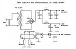
diode multiplier. The input harmonic voltage (Fig. 14.21) is applied to the transformer. Two phase-shifting chains are included in the secondary winding of the transformer. In them, the phase of the harmonic signal is shifted by 120 °. As a result, phase-shifted signals pass through the diodes. At the input resistance of the transistor, they are summed up. The third harmonic of the total pulsating signal is highlighted by the contour. The ratings of the elements of the phase-shifting chains are designed for a frequency of 400 Hz.

Rice. 14.22
Detector frequency doubler. Such a doubler (Fig. 14.23) is based on full-wave rectification on two transistors VT1 and VT2. The negative half-wave of the output voltage of the op-amp passes through the transistor VT1, and positive - through the transistor VT2. Resistors R6 and R8 are chosen the same, so the transmission coefficients of both half-waves are equal. To eliminate the distortion of the output signal shape caused by the influence of the threshold initial section of the characteristics of transistors, an op amp with a non-linear OOS is used. With a potentiometer R2 the output of the op-amp is set to a voltage corresponding to the minimum distortion of the output signal. The doubler works well with a triangular input signal. For this input waveform, up to ten multiplication circuits can be connected in series.


Rice. 14.23 Fig. 14.24

Rice. 14.25
differential doubler. The frequency doubler (Fig. 14.24) consists of an emitter follower assembled on a transistor VT1, and an amplifier stage built on a transistor VT2. The input signal through the capacitor C1 enters the base of the transistor VT1. In the emitter, this signal is added to the signal that passes through the transistor VT2. Transistor VT2 works in non-linear mode. It passes the negative half-waves of the input signal. The phase-reversed input signal will be subtracted from the emitter follower signal. The level of interacting signals can be adjusted by resistors R4 and R5. Resistor R4 controls the amplitude of the negative half-wave, and the resistor R5 adjusts the ratio of the emitter signal to the collector signal.
Square wave frequency doubler. Device (Fig. 14.25, a) converts the input harmonic waveform to a square wave signal with double the frequency. The input signal enters the emitters of the transistors VT1 and VT2. Transistor VT1 works in restricted mode. The second transistor also limits the signal, but due to the capacitor C1, the output signal is shifted by 90 ° relative to the input. Two limited signals are summed through resistors R6 and R7. Total bipolar signal using transistors VT3 and VT4 converted to a double frequency signal. Plots of signals at various points are shown in fig. 14.25, b. The doubler operates in a wide frequency range from 20 Hz to 100 kHz. This range can be covered by applying the appropriate capacitance of the capacitor C1. The input signal must have an amplitude of at least 2 V.
compensation multiplier. The compensation type frequency multiplier (Fig. 14.26) is built on a single transistor. The amplitude-limited signal is summed with the harmonic input signal at the resistor R1 In Devl tata, a signal is generated at the output, the frequency of which is 3 times higher than the frequency of the input signal. The output waveform is not perfectly harmonic. This signal must be filtered to reduce high harmonics. The waveform is greatly affected by the clipping level of the transistor. At small cutoff angles of the output signal, the high-frequency spectral components are significantly reduced. In this case, the amplitude of the third harmonic also decreases.


Rice. 14.26 Fig. 14.27
OU divider. Divider (Fig. 14.27, a) is built on the exact-ropany of the total signal at the output of the op-amp. On the Input 1 a local oscillator signal with an amplitude of 0.1 V is applied, Input 2 - converted signal. The dependence of the output signal amplitude on the converted signal is shown in fig. 14.27, b.
A frequency multiplier is called such a GVV, the oscillation frequency, at the output of which is 2, 3, ..., n times higher than at the input.
The frequency multiplier circuit is similar to that of a conventional radio frequency amplifier. The multiplier differs from the amplifier in that the output circuit of the multiplier is tuned to the second, third or n-th input voltage harmonics. Therefore, the load is allocated the power of the harmonic to which the output circuit is tuned.
From the analysis of the oscillation mode of the second kind, it is known that with an increase in the harmonic number, the amplitude of the harmonic components decreases: I n \u003d α n, Imah- Therefore, the useful power and efficiency of the multiplier are less than those of the amplifier. The multiplication mode is used in low-power transmitter stages, the low efficiency of which practically does not reduce the efficiency of the transmitter in practice.
The principle of constructing transistor frequency multipliers is based on the use of two physical processes: the selection of the desired harmonic from the collector current pulse and the nonlinear nature of the change in the collector capacitance from the change in the collector voltage.
Transistor frequency multipliers, operating on the principle of extracting the desired harmonic from the pulse, provide multiplication at relatively low frequencies. This is because with an increase in the operating frequency, the collector current pulse expands (up to 180 °) and the content of higher harmonics in it decreases sharply. In practice, multipliers based on this principle operate at frequencies up to 0.3 Ѡ t.
For multiplication at higher frequencies, the non-linearity of the collector capacitance is used. This allows you to get at the output of the multiplier a frequency greater than the cutoff frequency of the transistor. On fig. 2.12 shows a diagram of a transistor frequency multiplier operating at both low and high frequencies. The voltage of the fundamental frequency is applied to the input of the circuit, to which the circuit is tuned in the base circuit of the transistor. Filters are included in the collector circuit, highlighting a given harmonic at the load.
Transistor generators operate at frequencies up to 10 GHz. To obtain power at higher frequencies, after the transistor generator, frequency multipliers on semiconductor diodes - varicaps and varactors are included.
In semiconductor devices, the capacitance of the p-n-junction consists of two components: barrier (1) - the main one with a closed transition and diffusion (2) - the main at the open transition.
Graphs of the dependence of the capacitances of the p-n-junction on the voltage across it are shown in fig. 2.13. Curve 3 reflects the resulting capacitance of the pn junction. For the operation of the multiplier on the characteristic C res \u003d f (U) choose a working point A, applying an appropriate bias voltage.
 Diodes designed to operate in the mode of small amplitudes compared to the bias voltage are called varicaps. The properties of a varicap are determined by the properties of only the barrier capacitance of a barred junction.
Diodes designed to operate at high amplitudes are called varactors. In varactor multipliers, work occurs both in the region of the closed and in the region of the open transition.
The principle of operation of the varactor frequency multiplier is based on the use of the non-linearity of the capacitance of the pn junction. When a harmonic voltage is applied to the p-n junction, the current through the junction will be non-harmonic (Fig. 2.13.6). This current contains higher harmonic components. The use of an open p-n-junction area leads to an increase in the level of higher harmonics.
The varactor can be included in the multiplier circuit both in parallel (Fig. 2.14, a) and in series (Fig. 2.14.6). The input circuit of the multiplier is tuned to the fundamental frequency, and the circuit of the output circuit is tuned to the second or third harmonic. Such a frequency multiplier is passive, since the energy of the output oscillations at the frequency rno is determined by the energy of only one input voltage source with a frequency ω.
The advantage of the parallel multiplier circuit is that one terminal of the varactor in it is at zero potential. This makes it possible to place the varactor on a large radiator and improve the thermal regime, which means increasing the useful power.

A series circuit (Fig. 2.14.6) provides better stability of operation, since the inductance of the leads and the capacitance of the case are part of the oscillatory system of the multiplier. But in this scheme, the conditions for heat removal become more complicated.
The best power conversion efficiency in a varactor is achieved by selecting the optimal value of the bias voltage corresponding to a certain value of the input voltage. When the amplitude of the input voltage changes, the conversion efficiency also changes.
Auto-bias ensures that the bias voltage changes as the input voltage changes, thus maintaining optimum conversion efficiency.
Varactor frequency multipliers are used to double or triple the frequency. To obtain a multiplication of a higher multiplicity, several doublers or triplers are connected in series.
2.10. Connection diagrams for transistor generators
To increase the output power of the GVV, several transistors are connected in parallel or in series to operate on one common load.
When transistors are connected in parallel to work on one common load, the same electrodes of the transistors are connected to each other in parallel. In this case, the currents of the individual transistors in the common wire are added up and the total power is released in the output circuit.
Transistors connected in parallel must have the same parameters, otherwise one of the transistors will shunt the other transistor and the load. A significant variation in the parameters of transistors leads to the need to apply additional circuit solutions, equalizing the operating modes of individual transistors. However, this leads to a complication of the circuit, and consequently reduces the reliability of its operation. Therefore, they are limited to switching on no more than two or three transistors in parallel.
Due to the complexity of tuning and the decrease in reliability, circuits with parallel connection of transistors are rarely used.
Push-pull generators of low power (tens of watts) at frequencies of 1-10 MHz can be performed on transformers with magnetic coupling, as shown in Fig. 2.15. The transistors in this circuit operate in class B mode, i.e. with a cutoff angle of 0 = 90°. When an alternating excitation voltage is applied to the input in the collector circuits, the collector current pulses are phase-shifted by 180°. According to the current of the first harmonic, the transistors are connected in series.
VT1 leaking from the collector VT1 through transistor VT1, then the emitter - collector section of the transistor VT2, through the load T2 to the collector of the transistor VT1.
Collector current of the first harmonic of the transistor VT2 leaking from the collector VT2 through the collector - emitter section VT2, through emitter - collector VT1, through the load and to the collector VT2.
Through the load T2 the collector currents of the first harmonic flow in the same direction and are therefore summed up. In the common power wire, the currents of the first harmonic are directed towards each other and cancel each other out.
At the output of this circuit, with its good symmetry, there are no higher harmonics, since the even harmonics of the collector currents of both transistors are compensated in the output transformer, and the odd harmonics in pulses with a cutoff of 0 = 90° are practically absent.
2.11. Schemes of output stages of radio transmitters
 The radio frequency oscillations created by the generator are transmitted to the antenna for radiation. To do this, the transmitter antenna must be connected to the output circuit of the last transmitter stage. The stage loaded with the antenna is called the output stage. The transmitter output stage is the most powerful stage and draws the most energy from the power supplies. Therefore, the energy performance of the output stage mainly determines the energy performance of the transmitter as a whole. Therefore, the output stage should be as efficient as possible. In addition, the output stage operates in the oscillation mode of the second kind, “the higher harmonic components of the current of its output circuit can be transmitted to the antenna and radiated by it, interfering with other radio stations. To eliminate this, the output stage must provide sufficiently good harmonic filtering.
The operating mode and energy performance of the output stage depend on the electrical parameters of the antenna and the method of its connection with the output circuit of the generator.
Depending on the method of connecting the antenna, two output schemes are distinguished - simple and complex.
A simple output circuit is one in which the antenna is directly connected to the output circuit of the oscillator, as shown in Fig. 2.16, a. In this scheme, the antenna, together with tuning and communication elements, is part of the output circuit, which is the load of the generator. The output circuit is called the antenna circuit here. It must be tuned to the specified frequency and have a resistance equal to the generator's optimum load equivalent resistance.
It is known that the most complete transfer of oscillatory power to the antenna occurs when the input impedance of the antenna is matched to the output impedance of the generator. In a simple circuit, the antenna circuit is tuned to a given frequency using the tuning coil L n, and the load resistance is selected by changing the coupling inductance or capacitance.
If the transmitter operates on one fixed wave, then the conditions for the implementation of the most favorable generator mode and the most complete energy transfer to the antenna are achieved as follows. First, the antenna circuit is tuned to the operating frequency of the generator, and then, without changing the circuit settings, the value of the equivalent resistance of the circuit is selected to ensure the optimal operation of the generator.
When the antenna is directly connected to the output circuit of the generator, the energy is transferred to the antenna most fully and this achieves a higher efficiency of the generator, which is the advantage of a simple output circuit.
The disadvantage of a simple circuit is low harmonic filtering and unreliable operation in case of antenna breaks. When the antenna breaks, the load resistance decreases and the generator may be in an undervoltage mode. In this case, power losses on the electronic device may exceed the allowable ones and destroy the device.
In a complex output circuit, there are two circuits in the generator output circuit (Fig. 2.16.6). One of them is connected directly to the output circuit of the generator and is called intermediate. The second circuit is created by the elements of the antenna and is called the antenna circuit. Both circuits are tuned to the operating frequency of the generator. The optimal load resistance in a complex circuit is selected by selecting the connection between the intermediate circuit and the antenna (using the successive approximation method).
The advantage of a complex circuit is better harmonic filtering. In addition, a complex circuit is more reliable, since when the antenna breaks, the generator goes into an overvoltage mode and the power loss for heating the electronic device decreases. The disadvantage of a complex circuit is low efficiency due to energy losses in the coupling elements and the intermediate circuit.
The complex output circuitry is used in high to medium power transmitters where better harmonic filtering is essential and large circuitry and complexity can be tolerated.
In low-power communication transmitters, for which their small overall dimensions, mass and simplicity of the circuit, as well as economy are of decisive importance, a simple output circuit is used.
To control the operating mode of the electronic device and tune the circuit to resonance, a device is included in the output stage of the transmitter to measure currents in the output and input circuits of the generator.
Chapter 3. AUTOGENERATORS
3.1. Principle of self-excitation
To create radio frequency oscillations in radio transmitters, the phenomenon of the occurrence of electrical oscillations in an oscillatory circuit is used, into which a certain amount of energy is introduced from the outside, i.e., the oscillatory circuit serves as the primary source of electrical oscillations in radio transmitters.
If the electrical circuit LC to introduce a certain amount of energy from the outside, for example, by charging the capacitor C, then free damped radio frequency oscillations appear in the circuit.
In order for the oscillations to be undamped, i.e., their amplitude does not decrease, it is necessary periodically, in time with free oscillations, to replenish the energy in the circuit. This can be done periodically by connecting an EMF source to the circuit, which will recharge the circuit capacitor. When the amount of energy entering the circuit is sufficient to compensate for all energy losses in it, the oscillations in the circuit will be undamped.
To create undamped oscillations in the circuit, it is necessary to replenish energy once per period. And since the oscillation frequency is high (hundreds and thousands of kilohertz), only a special high-speed device - an electronic lamp or a transistor - can connect a source of electrical energy to the circuit to replenish energy in it.
In order for energy replenishment to enter the circuit in time with free oscillations (with its own oscillations), it is necessary that the oscillations themselves control the current of the power source. To do this, the generator circuit has a feedback (OS) of the output circuit with the input. Thus, a self-excited generator consists of an oscillatory circuit, an electronic device, a power source, and positive feedback elements. /
 In the oscillatory circuit, the energy of the generated oscillations is released, the frequency of which is determined by the parameters of the circuit L and C. The electronic device acts as a regulator of the energy consumption of the power source. Feedback elements can be an inductor or a capacitor. The power supply replenishes the energy in the loop. Thus, a self-excited generator is
_____________________________________________________________
Fig.3.1. block diagram of the oscillator
1-chain OS; 2-reinforcing element; 3-oscillatory circuit;
4-power supply.
a device that creates radio frequency oscillations using an oscillatory circuit and feedback elements. And since oscillations in such a generator occur automatically, immediately after the power sources are turned on, it is called an autogenerator (Fig. 3.1).
For the operation of amateur radio stations in the high-frequency sections of the VHF and microwave bands, the local oscillators of receivers and transmitters become multi-stage. The master oscillator, which is the first stage of the local oscillator, usually operates at a fairly low frequency.
This is done for various reasons.
At low frequencies, it is easier to select the required quartz resonator or create more favorable conditions for frequency stabilization in generators with parametric stabilization.
At low frequencies, it is easier to organize the generator frequency control.
Lack of high-frequency quartz resonators in radio amateurs.
A multi-stage local oscillator consists of a generator and the subsequent several stages of frequency multiplication to the required operating value. So, for example, if we need to develop a converter for receiving signals in the 145 MHz band for a HF radio receiver with an amateur band of 21 MHz, we need to create a local oscillator with an operating frequency of 123 MHz.
This operating frequency can be obtained in several ways, using a wide variety of quartz resonators. One option may be to use the RR at a frequency of 13.66 MHz.
In this case, the generator itself must generate a frequency of 13.66 MHz, and the next two stages must multiply this frequency by 9 times, i.e. each of the stages must multiply the frequency by 3, or, as they say, each of these stages must operate in the frequency tripler mode.
As a rule, multiplier cascades are rarely used in amateur practice.
Circuits of simple frequency multipliers
In fact, the frequency multiplier is not some unusual, special cascade, but is a conventional high-frequency amplifying cascade. Figure 1 shows two circuits of simple frequency multipliers.
The circuit in Fig. 1 is a conventional UHF cascade. Resistors R1, R2 and R3 set the operating mode of the transistor VT1. The L1C3 circuit must be tuned to the frequency of the desired harmonic of electromagnetic oscillations entering this stage through C1 from the previous stage.
The signal of the desired frequency selected in the L1C3 circuit is fed to the next stage through the capacitor C5. Resistor R4 and capacitor C2 prevent RF energy from entering the power circuit (they are blocking elements).
The circuit in Fig. 2 already has significant differences from the previous circuit. The main difference is that the transistor VT1 in this circuit operates in the key mode, i.e. the current through the transistor flows only during the passage through the base of the transistor of the pulse of the positive half-cycle of oscillations that come through C1.
The L1C3 circuit is a parallel load tuned to the desired harmonic frequency. The signal of the desired frequency selected in this circuit is fed to the next stage through C4.
Push-Pull Doubler Circuits
The requirement for the need to contain minimal noise in the local oscillator signal, which depends on the presence of a large number of harmonics in the signal, set the task of reducing the number of these harmonics.
It is possible to complete the task with the help of special two-transistor multipliers, in which these two transistors are connected in a push-pull circuit. Figure 3 shows a schematic diagram of a push-pull frequency doubler.
Fig.3
The transistors in the circuit in Fig. 3 are connected according to the so-called push-pull circuit. The fact is that antiphase signals arrive at the bases of these transistors and during one of the half-cycles of the incoming signal the transistor VT1 works, and during the second half-cycle the transistor VT2 works.
Since these two transistors operate on a common load for them, then in this load, for one period of the frequency of the signal entering the cascade, two periods of a new, doubled frequency appear.
If the signal coming to such a stage is strong enough, then in exactly the same way the fourth harmonic of the signal coming to the input can be distinguished at the output.
As you have already noticed, a push-pull doubling cascade selects only even harmonics in its load. All odd harmonics are suppressed and are no longer present in the subsequent signal.
The signal to be doubled is allocated in the L1C loop. Over the coil L1 is wound coil L2, made of two separate wires. Coil L2 is made as follows. It is necessary to measure and cut off two identical pieces of insulated thin wire, the length of which should be sufficient for winding 3 ... 5 turns over the L1 coil, of which the L2 coil will consist.
Then the two ends of both wires are clamped and these two wires are twisted into a single bundle. After winding the L2 coil with the resulting bundle and fixing its turns, the beginning of one of the wires is connected to the end of the other wire. In this way, the middle point of the coil L2 is formed, which is connected to the housing (grounded). The remaining end of the first wire and the beginning of the second wire are connected, through capacitors C1 and C2, to the bases of transistors VT1 and VT2.
In this way, an antiphase supply of signals to the bases VT1 and VT2 is organized.
Fig.4
Figure 4 shows a schematic diagram of the second version of a push-pull frequency doubler. The scheme of this option is somewhat simpler and contains fewer parts, but works just as efficiently. As you have already noticed, the load of the doubling stage, the role of which is played by the L3C3 circuit, is connected in series in this embodiment.
In this case, you must always remember that the output capacitances of the transistors add up and the tap for connecting the coil should be located closer to the RF-grounded end of the coil.
The current through the transistors, and with it, the amplification of the doubled signal is controlled by the selection of the resistance value R1. Capacitance C1 is usually taken in the range of 120 ... 200 pF.
In the transmitting and receiving paths of communication systems, as well as in some measuring devices, the nonlinear transformation of a harmonic oscillation is widely used, as a result of which the frequency of this oscillation increases by k once, k is a positive integer. Such a non-linear transformation is called a frequency multiplication, and the device that implements it is called a frequency multiplier.
Thus, a frequency multiplier is a device that increases in k times the harmonic frequency. If a signal is applied to the input of the multiplier, then a signal is generated at the output, and some multipliers increase in k times and the initial phase, i.e. .
Frequency multipliers are used in the formation of oscillations with high frequency stability. This applies primarily to the formation of high-frequency oscillations during quartz stabilization of the master oscillator frequency. The natural frequency of quartz is determined by the expression, b is the thickness of the quartz plate. For frequencies above 50 MHz, the plate should have a thickness on the order of hundredths of a millimeter. Such plates are very difficult to manufacture, they have poor mechanical strength. Therefore, this stabilization method is used in generators with a frequency of up to 5 MHz, in some cases up to 50 MHz. Higher frequency oscillations are obtained using frequency multipliers.
As frequency multipliers, the most commonly used circuit is a non-linear resonant amplifier with a circuit tuned to the desired frequency. As shown earlier, the current pulse spectrum of a non-linear transistor amplifier (operating in current-cutoff mode) contains harmonic components with frequencies that are multiples of the input signal frequency. If the amplifier circuit is tuned to a frequency k- th harmonic, then a harmonic oscillation with the frequency of this harmonic will be formed at the output.
It is known that the amplitude k th harmonic is given by ![]() . Therefore, the operating mode of the amplifier as a frequency multiplier should be such that the amplitude of the desired harmonic is the largest. At a certain value, this is ensured by the optimal cutoff angle, at which = max.
. Therefore, the operating mode of the amplifier as a frequency multiplier should be such that the amplitude of the desired harmonic is the largest. At a certain value, this is ensured by the optimal cutoff angle, at which = max.
It has been practically proven that such a cutoff angle, at which the graphs have well-defined maxima, is equal to ![]() . Knowing the cutoff angle makes it possible to determine the amplitude of the input signal and the voltage of the operating point of the frequency multiplier:
. Knowing the cutoff angle makes it possible to determine the amplitude of the input signal and the voltage of the operating point of the frequency multiplier:
 ,
, ![]() .
.
Here is the average slope of the I–V characteristic of the transistor for k th harmonic, is the cutoff voltage.
The considered multiplier circuit can provide a frequency multiplication of 2, less often 3 times and no more, because the amplitudes of the higher harmonics of the collector current rapidly decrease with increasing frequency. In cases where it is required to multiply the signal frequency by tens or more times, it is possible to multiply the frequency multiple times by turning on several multipliers in series. However, it is more appropriate to use another method.
It is known that the spectrum of a periodic sequence of video pulses contains an infinite number of harmonic components with frequencies that are multiples of the pulse repetition rate . The amplitudes of these harmonics at are quite large in a wide frequency range (the width of the main lobe of the spectrum is ). Therefore, using narrow-band filters, it is possible to isolate harmonics with frequencies greater than ten.
The scheme of such a multiplier contains a nonlinear converter of a harmonic oscillation into a periodic sequence of very short duration video pulses with a repetition rate equal to the frequency of the input oscillation, i.e. . The necessary harmonic of the spectrum of these pulses is separated by a filter.
An even higher multiplication factor can be obtained by using a periodic sequence of radio pulses. The spectrum of such a signal is concentrated in the frequency region of the carrier wave. This spectrum contains harmonic components with frequencies that are much higher than the frequency of the input oscillation. The scheme of such a multiplier is complex, since it must contain a pulse amplitude modulator that converts oscillations with a frequency into a periodic sequence of radio pulses with a repetition rate.
Frequency multiplication can also be carried out using parametric circuits (for example, circuits with a varactor). This issue is not addressed in this tutorial.