USB to UART to CH340G converter:
modifying to RS232TTL, testing, comparing
April 2017 1. What is TTL and what does USB have to do with it?
Somehow, Ali attracted my attention to a very inexpensive usb to uart converter. At first I wasn't quite sure what this thing really was. The product name in English looked like this: "USB to TTL converter UART module CH340G CH340 3.3V 5V switch". The mention of UART and the CH340G chip seemed to dispel doubts, but I didn't like the phrase "USB to TTL", which was also visible in the photo of the module, on its underside. The fact is that this phrase does not make sense, which means that it opens up wide scope for free interpretation.
In theory, translated into Russian, the phrase " USB to TTL" should mean "converting USB to TTL". No one needs to explain what USB is now, but not many have heard about TTL. Therefore, let's turn to history and see what is TTL.
Interestingly, both Google and Yandex, in response to the query "What is TTL", gave links about TTL from a completely different area. So what is it, in relation to electronics? The abbreviation TTL in Russian does not differ from the English version and stands for transistor-transistor logic (TTL). Initially, this concept implied the features of the internal structure of some digital microcircuits, a set of technical solutions, including circuitry and technological ones. Among other things, the TTL standard also set a method logical signal coding. So, for example, a logical zero was encoded by a voltage close to the common power wire. Moreover, the common wire was connected to the minus of the power source and was taken as the zero potential - "ground". And the logical unit was encoded with a voltage close to the supply voltage + 5V. The +5V supply voltage itself has also become an integral part of the TTL standard.
It should be noted that TTL microcircuits at one time were very widespread. In the Soviet Union, perhaps the most famous was the K155 series. The widespread use of these and similar microcircuits forced hardware developers to adhere to the same methods of encoding logic zero and logic one signals, which were provided for by the TTL standard, for compatibility purposes.
But nothing stands still. TTL microcircuits, built on bipolar transistors, soon became obsolete. They greatly lost to more modern microcircuits both in terms of speed and energy consumption. They began to be replaced by other families of microcircuits based on MIS structures (metal-dielectric-semiconductor), and in a simple way - on field-effect transistors. But the signal coding standard was not going to become obsolete, so many new microcircuits, even without being directly related to TTL, remained compatible with TTL. The TTL microcircuits themselves gradually became part of history (although they are still used in amateur designs to this day), and their common name - the abbreviation TTL - acquired a slightly different meaning. Now TTL should be interpreted as "the voltage level standard for encoding logical zeros and ones used in TTL microcircuits."
And what, in view of the foregoing, can the words "USB to TTL" mean? I think it is now clear why this phrase does not make sense.
2. Interface converter on the CH340G chip
I ended up ordering this product. It cost me 44.30 rubles with shipping, that is, almost for nothing. But this is not the case when cheap means bad. When connected, it was immediately identified in the system (Windows 8.1). There were no problems with the drivers. Previously, I already connected another converter to the CH340 (the one in the form of a USB-COM adapter cable), so the driver was already installed. I must say that last time there was no need to look for a driver and install it manually - everything turned out automatically. Now, the previously installed driver immediately recognized the new device.
As expected, it turned out to be a USB-UART converter, like the ones I bought earlier. Of the useful signals, only TXD and RXD are also output to the module connector. Of course, this did not suit me. Knowing that the microchip CH340G ensures the formation of a complete* set RS232 signals, I bought this module with the expectation of its further improvement. By the way, such a low price is largely a consequence of the "inferiority" of this module. With only TXD and RXD signals, its capabilities are severely limited. But with a full set of RS232 signals, the capabilities of the module and its scope become truly inexhaustible (it is not at all necessary to use the RS232 inputs and outputs strictly for their intended purpose). Such a port can even be considered as low-bit parallel port with arbitrary setting of signals on three outputs and arbitrary polling of the status of four inputs. On this site, you could already see different options for using a similar module. But a converter with a full set of signals usually costs an order of magnitude more expensive. Why overpay? For those who are friends with a soldering iron, the best solution is to buy a "semi-finished product" and bring it to a full state.
* Under the "complete" set of RS232 signals, here we mean the signals COM port, although the RS232 standard provides for many other signals not used in COM.
I will add that the module has three LEDs (all red), one of which signals the supply voltage from USB, and the other two display the status of the TXD and RXD signals (lighting up at logic zero, that is, when the voltage is low relative to GND).
3. Refinement of the UART module to a full-fledged RS232TTL
.jpg)
| Conclusion | Purpose |
|---|---|
| 2 | TXD output |
| 3 | RXD input |
| 9 | CTS input |
| 10 | DSR input |
| 11 | RI input |
| 12 | DCD input |
| 13 | DTR output |
| 14 | RTS output |
chips CH340G
with RS232 signals
In general, the whole refinement consisted only in soldering to the corresponding legs of the microcircuit. To do this, it was first necessary to cut a window in a heat-shrinkable shell. Conformity of conclusions chips CH340G and RS232 signals see the table in Table 1.
As can be seen from the table, all signals, except for TXD and RXD, are on the same side of the microcircuit, but TXD and RXD are already output to the connector, so it was necessary to solder additional wires only on one side.
4. Testing the converter on the CH340G chip
To make sure that the module is working, and that it really ensures the operation of all the signals inherent in the COM port, I conducted its thorough testing. All tests passed, as they say, without a hitch, from which I conclude that this interface converter can be recommended for use in any devices and designs that require connection to a computer via RS232TTL. Including for use as a microcontroller programmer, as described in the article.
Testing was carried out using several scenarios for the Perpetuum M program. You can also test your own converter. Download (they are packed in one archive) and separately. Don't forget to check and if necessary change the port number in the scripts, otherwise they won't work. You can find out the port number in your case through the Windows Device Manager. At the beginning of each script (and they can be opened with a text editor such as notepad) you will see the line "PortName="COM3";". Instead of the number 3, put the number you need. For example, if a COM4 device appears in Device Manager when a module is connected, then in each scenario you need to specify "COM4" instead of "COM3".
Now I'll tell you more about the testing process. First I installed a jumper between the pins of the connector TXD and RXD so that the data from the transmitter immediately gets to the receiver. Thus, I "looped" the port so that it could transmit data to itself. This allows you to test both transmitter and receiver at the same time without connecting to another port. Then I ran the script "Testing a COM port by transferring a file through it" and selected a randomly turned up 653 KB file. File copying was successful. The copied file turned out to be absolutely identical to the original, which indicates the health of the receiver and transmitter of the UART module.
Next, I sequentially ran the scripts "Test TXD COM port output", "Test DTR COM port output" and "Test RTS COM port output", having previously connected a voltmeter to the corresponding output for each case. By entering zeros and ones into the program's dialog box, I made sure that they are successfully displayed on the outputs of the port. At the same time, it turned out that the TXD output displays logic levels without inversion, that is, when zero is output, a low voltage appears, when a unit is output, it is high, and the DTR and RTS outputs work with inversion. This should be taken into account when using this module in development.
Then I launched the "Test COM port inputs" script, which displays the status of four port inputs in real time: CTS, DSR, RI, DCD. Through a 5.6K resistor, I began to connect one by one each of the inputs either to a common wire (GND), or to a + 5V power line. It turned out the following. All inputs are operational, all of them give an inverse state during a software poll. All have a "pull-up" to the supply voltage, that is, the "hanging" input has a logical unit level and, accordingly, due to the inversion, it is read as "0" by the software. When the input is connected through a 5.6K resistor to the GND connector pin, each input easily goes to a logic zero state (programmatically read as "1"), which means that the resistance of the built-in "pullup" is at least an order of magnitude higher than 5.6K. Note that in modules based on the PL2303 chip, it is much more difficult to "kill" the built-in "pull-up" because of its low resistance.
To summarize: in addition to the possibility of serial data transfer via UART, we have three independently controlled outputs ( TXD, DTR, RTS), of which one is direct (TXD) and two are inverse, as well as four software polled inverse inputs with a "pull-up" to the supply voltage ( CTS, DSR, RI, DCD). If you plan to use the UART, then there will be only two independent outputs, since the TXD output is the signal from the UART transmitter. This does not apply to the inputs - there will still be four of them.
I must say about one more possibility, which allegedly allows you to change the level of a logical unit at the outputs by rearranging the jumper, depending on what voltage the microcircuits connected to this module are powered by: 5V or 3.3V. That is, the issue of matching levels is being resolved. I am writing about this "chip" with some disdain, because it is implemented in a strange way and does not inspire confidence. However, there is no special need for it, because harmonize levels between 5V and 3.3V is easy in other ways. And here's the thing. The module has three pins: 5V, VCC and 3.3V. With a jumper (it is even included in the kit) you can close 5V and VCC, or VCC and 3.3V. Or you can not set it at all, since with the complete absence of a jumper, everything works the same as if it is installed between VCC and 3.3V. The voltage on the 5V pin corresponds to the voltage of the +5V wire of the USB port. On the VCC pin, in the absence of a jumper, there is a voltage of about 3.8V, and on the 3.3V pin - about 3.2V. If the jumper is installed between 5V and VCC, then, in principle, there are no questions - TTL levels work, that is, a logical unit reaches five volts. But if you install a jumper between VCC and 3.3V, then questions arise, because in this case the voltage on the 3.3V pin rises to 3.8V (as it was on VCC before the jumper was installed), and the logical unit at the port outputs reaches 3.6 ...3.8V, which is too much for 3.3V. Without a jumper installed at the outputs, the unit level also reaches 3.6 ... 3.8V. Maybe nothing will burn out in this case, but the emphasis on the maximum permissible values \u200b\u200bis not the best factor for reliability.
5. Advantages and disadvantages of the CH340G converter
Of the shortcomings, I noted only two minor trifles that can be ignored with a competent approach. One of them is not entirely successful agreement with the 3.3V standard. But if you don't use 3.3V power, or you do, but the task of matching levels is not a problem for you, then everything is in order. The second minus is that all the LEDs of this module of the same color are red, which makes you remember their location if you want to navigate by them. But in real practice, the need for LEDs is not so great, and if they are still needed, then you can replace them with your own.
There are definitely more pluses. First of all, pleases the absence of problems with the drivers. As I said above, for microcircuits CH340 drivers for Windows installed automatically, including the latest OS versions. But with converters on the PL2303 chip, everything is much more complicated. For older chips there are no drivers for new versions of Windows. And the old microcircuits in the past were released by the sea. If I'm not mistaken, this was the reason why the developers did not support the old microcircuits. It seems that there was some kind of copyright problem - there were a lot of counterfeit microcircuits on the market. And then the developers, without fundamentally changing anything in the new microcircuit, changed only how it responds to the driver's request. Roughly speaking, to the question "Who are you?", the new microcircuit began to answer: "I am Vasya-plus." And if the driver receives the answer "I am Vasya", then he tells this microcircuit: "Go through the forest, Vasya without a plus." That is, purely technically, the new driver could well work with the old microcircuit. As far as I know, there are even ways to get around this misfortune - either the new driver is somehow forced to work with the old microcircuit, or the old driver is "screwed" to the new OS.
Another convenience of this module is that the pin spacing of the CH340G chip is much larger, so soldering is much easier. This microcircuit has only 16 pins, among which basically only the most necessary, unlike the PL2303, where, apparently, there are pins for all occasions.

In my opinion, the high resistance of the "pull-up" of the inputs can also be considered a plus, which reduces the current of the logical zero, which means that it imposes fewer requirements on the signal source. If the requirements for protection against interference are very high, then you can easily organize an additional "pull-up" with an external resistor. When using this module as a role (see figure on the right), you can install all resistors with the same resistance (1K ... 4.3K). That is, it is not required to greatly underestimate the resistance at the CTS input.
I will also add that in the past I conducted a comparative test of two converters on microcircuits PL2303 and CH340. The CH340 definitely won - in extreme modes it was much more difficult to get failures in working with it. Although it was a converter of a different design (adapter cord), but, as it seems to me, one can expect that other models of converters of the CH340 family are no less reliable.
If you have questions or comments on this article, write to or mail.ru (jkit box).
From correspondence with a site visitor
05/12/2017 Guest:
Hello Eugene.
.htm
I have the same converter (one to one).
The fact is that I need to reflash the FlySky i6 equipment to 10 channels. Initially, the jumper is in the "VCC-3V3" position. Did I understand correctly that it should be left as is? Sorry, but I'm off topic, that's why I'm asking this question. I don't want to burn anything.
14.05.2017
Hello Vladimir!
The answer to your question depends on the technical characteristics of the equipment to which you connect the module on the CH340G. I have not encountered this equipment, so I can not say for sure. The link you gave gives a 404 error. But, even if the link worked, I would hardly have found the time to understand that equipment in detail. Try VCC-3V3 first. I don't think it will get any worse. Just in case, put 1 kΩ resistors in each signal wire (this is due to the fact that it is actually not 3.3 V, but more).
05/14/2017 Guest:
Hello Eugene.
Thanks for the advice! Indeed, it is better to start small.
And 1 kOhm is based on what current was it? (I just don’t know what currents flow through the signal wire, and I couldn’t find it anywhere)
17.05.2017
Hello Vladimir!
The question is worded incorrectly. Why do you need to know current? I took 1 kOhm "by eye", based on the fact that if somewhere, even in some way, 5 V is applied to the resistor in an emergency (and more, in theory, there should not be nearby), then the current will be 5 mA, which should not lead to negative consequences.
05/17/2017 Guest:
Hello Eugene.
He spoke about the current, because if it is close to zero, then there will be no voltage drop across the resistor and the output will be the same 3.6 V instead of 3.3 V. But I understood the meaning of your reinsurance, thanks for the comment.
19.05.2017
Hello Vladimir!
There are completely non-linear elements. And the point is not that the extra 0.3 V can break something with voltage, but just that even a small increase in voltage can suddenly cause a non-linearly fast increase in current. For example, protective diodes at the inputs, etc. may open. The resistor gives linearity to the circuit and prevents such a development of events. And normal currents are usually small (though not always), so a resistor shouldn't get in the way. An exception is a low-resistance pull-up at the input. Then the resistor will not allow it to "overcome" and will not work. This is detected by an oscilloscope, or even a voltmeter (in static mode).
05/19/2017 Guest:
Hello Eugene.
Thank you very much for the detailed explanation. Now at least I understand the mechanism of such protection. And then I already thought that the Chinese could deliberately overestimate the voltage, taking into account the drop when the load was turned on. Now it is clear that this is just a flaw.
20.05.2017
Hello Vladimir!
So that the voltage does not "sag" when the load is connected, the load capacity of the output is increased. "Extra" voltage is not added for this. Of course, 3.6V instead of 3.3V isn't that much, and it's unlikely that anything will break because of it. But it is dangerous to supply 3.8 V to the input of a microcircuit powered by a 3.3 V source, since the extra 0.5 V is already quite capable of opening a protective diode at the input, and if the output load capacity is high, it can damage the input connected to it . The "safety" resistor prevents this.
The use of materials from this site in publications is permissible only if these materials are accompanied by links to the source - site site indicating the author: E.A. Kotov. Copyrights are protected by the laws of the Russian Federation. Evgeny Kotov. 2017
Very often, many novice electronics enthusiasts are faced with the need to pair levels, connect the computer's com port via rs232 with various devices that have different TTL data transfer levels.
And very often when collecting another scheme, disappointments occur.
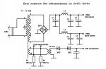
Below is a fully working diagram of the Com adapter with a description.
You can use this device when connecting the Dir300 router through the internal Com port to various devices with different signal levels. The same is true for other device pairings. Receivers with computers, for example. A com adapter is always useful.
For the manufacture of RS232-TTL, a breadboard was needed, but in the end there were no interference, all the data was correct and complete.
Details
Chip
MAX232 or its variant.
Resistors
400 kOhm.
5 kOhm
Capacitors
They are selected for a specific chip marking according to the table in the first figure.
Peculiarities
Don't forget about pull-up resistors. The most common mistake. Also, do not forget to connect GND (grounding of the COM port, microcircuit and connected device in one line)
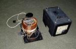
Photo of manufactured working COM adapters


Other articles in the section:
OBSTACLES SENSOR IR BUMPER
Probably, someone has already read the messages on our forum exmortis about making a USB-TTL cable from improvised means.
We decided to issue this as a separate article-guide. Thank you exmortis for the material provided.
Annotation: This article is an addition to the serial interface, which is recommended to read first.
As you know from the above article, the Ritmix RZX-50 prefix can be connected to a computer via uart ttl, but since the voltage signals do not match the rs-232 standard, an adapter is needed. As a ready-made solution, you can use a special converter, for example, or even this one.
The difficulty is that such solutions may not always be available, and if they are available, the declared price may be quite high.
However, you can fit a regular usb-rs232 (com) adapter cable, which is sold in any computer store. For example, like this:
Gembird usb-rs232 uas111 cable. It is convenient because the controller is hidden in a neat box. True, it is sealed, so to open it, you will either have to saw it or cut off the plastic with a soldering iron.
In principle, any other similar cable will do, however, you need to pay attention to the ease of access to the board with the controller. On some cables, it is hidden in the rs-232 connector, which is difficult to open, while on others there may be a microchip-drop, which is not easy to solder to. In the end, such a cable may be based on some exotic chip.

Chip pl2303. First of all, legs 1 (TXD) and 5 (RXD) are of interest, the numbering of the legs goes counterclockwise from the corner marked on the chip itself with a dot.

Reverse side with max213 chip. The signal from the 1st leg of pl2303 comes to the 6th leg of the max, and the signal from the 5th leg goes to the 19th leg of the “maxima”.
In principle, this chip is not needed for uart-ttl, it can even interfere. Therefore, it must be carefully soldered, and the easier it will be soldered to the contact pads.

The max213 chip is soldered. The red wire is soldered to the TXD signal, the yellow wire is soldered to the RXD signal, the black wire is ground. Subsequently, you can connect according to the Antony scheme, connecting the wires “crosswise”, i.e. RXD of the controller to TXD of the set-top box, and TXD to RXD, respectively.

Ritmix RZX-50 serial interface pins.
The second important part is the direct connection to the computer and setting up the connection.
Below we will consider a specific situation when W7 x64 is installed on a computer (laptop), and Xubuntu 11.10 x32 is installed in the VirtualBox virtual machine. Everything described below is also true for any distribution of linux.
The cable soldered as above is connected to the computer (while the rzx-50 is NOT connected). Naturally, the driver will not be installed by the system, but this is not required. We load xubuntu in a virtual machine, forward the connected device inside (should be referred to as Prolific Technology Inc. USB-Serial Controller). Then load the console and enter dmesg. One of the last lines should be the definition of the connected device (pl2303) and its reflection on the file system - in this case it is /dev/ttyUSB0. We remember this name.
Now we need to install minicom. The command is standard: "sudo apt-get install minicom". Run the setup: "sudo minicom -s" and get into the configuration menu. In Serial port setup set /dev/ttyUSB0 as Serial Device, flow rate is set to 56700 8N1, hardware and Software Flow Control is turned off (No). Next, in Modem and dialing, you need to erase the Init String and Reset String lines.
We exit the setup and start minicom in normal mode (sudo minicom). Now you can test the cable by shorting the wires from the TXD and RXD signals. If the corresponding symbols appear on the screen when you press any keys in minicom, then the cable is working.
Now you can connect the set-top box to the wires in the way indicated above, and turn it on, enjoying the output in the terminal emulator window. When prompted to enter a password, enter "root". If garbage or extraneous characters periodically appear during input and output, then something is wrong with the ground (most likely broken). Ideally, the ground should also not be shorted to the TXD and RXD signals in any way.
From the Editor: I personally immediately remembered the end of the 90s, when the Palm era began. At that time, I was the proud owner of the Handspring Visor Deluxe, the most powerful PDA at that time (the word “tablet” had not yet been invented). So, due to the lack of USB ports (yes! yes!) I had to make the RS232-TTL cable myself. Moreover, since the Visor had three-volt signals, and the Maxim chip that provided the desired signal level was scarce, I had to hang a voltage divider from 5 to 3.3v on the “output” leg so as not to burn the device.
Now everything is much simpler, and you can focus on more meaningful activities, such as making a feasible contribution to the creation of an alternative firmware for the RZX-50 🙂
Almost all microcontrollers have a serial port on board - UART. It works according to a standard serial protocol, which means it can be easily connected to a computer on COM port. But there is one problem here - the fact is that the computer RS232 he takes for logical levels +/- 12
volt, a UART operates at five volt levels. How to combine them? For this, there are several options for level converter circuits, but the most popular is still on a special converter. RS232-TTL. This is a microchip MAX232 and its analogues.
Almost every company makes its own converter, so it will fit here ST232, and ADM232, and HIN232. The circuit is as simple as three pennies - input, output, power and piping of five capacitors. Capacitors are usually placed 1uF electrolytes, but in some modifications 0.1uF ceramics. I soldered everywhere 0.1uF ceramics and usually this was enough. :) Works like a clock. If at high speeds it will fail, then it will be necessary to increase the capacity.
By the way, there is also MAX3232 this is the same, but at the output it does not have 5 volts TTL, but 3.3 volts TTL. It is used for low voltage controllers.
I made myself one such universal cord so that it would be convenient to cling to the controllers by UART. For overall compactness, I shoved the entire circuit straight into the connector, since I had ST232 in soic case. The result was a handkerchief no more than a ruble coin. Since there were no small SMD capacitors at hand, I had to solder the conders from above, whoever was in what much. The main thing works, although it did not turn out very beautifully.

If you doubt that you will succeed in such a small installation, then I have divided the board for you into a standard PDIP case. It will be the size of a matchbox, but you don’t need to grind.

After assembly, it is simply checked:
Plugs into socket COM port. Apply 5 volts of power to the circuit, and then close Rx on the Tx(I have green and yellow wires).
Then you open any terminal, at least HyperTerminal, cling to the port and start sending bytes, they should immediately come back. If this does not happen, check the circuit, somewhere there is a jamb.
If it works, then everything is simple. The wire that comes from pin 9 of the chip MAX232 it transmitting output, get him on his leg RxD controller. And the one from the leg 10 - receiving, feel free to put him on the conclusion TxD controller.
Microcontrollers in Arduino (ATmega328, 168, 2560) use, among other interfaces, a hardware-implemented serial interface (UART). The ATmega2560 MK (Arduino Mega) implements four UARTs at once. The interface uses two wires - RX (receive) and TX (transmit), where the digital signal encodes the bit values "0" and "1" with the voltage on the wire. The value "0" corresponds to 0V, and the value "1" corresponds to the operating voltage of the integrated circuit (5V or 3.3V, depending on the model and mode of operation of the MK). This type of coding is also called transistor-transistor logic (TTL). the voltage on the wire directly affects the state (open / closed) of transistors that provide digital signal reception and transmission.
The computer serial port (COM port), which is rarely seen in modern models of compact computers, operates according to the old telecommunications standard RS232, where the signal encoding is different: the value "0" is encoded with voltage from + 3V to + 25V, and "1" - negative voltage from -3V to -25V. In COM ports of personal computers, voltages of +13V and -13V are usually found.
A large voltage difference makes the RS232 connection more resistant to interference, however, in modern digital devices, a TTL-compatible serial port is more often used, or USB - a much more modern and high-speed interface.
For comparison, the figure below shows the TTL serial and RS 232 signals taken when transmitting the value of one byte.
To convert the RS232 signal to TTL and vice versa, you need to invert it (although this can be done in software) and convert the voltage. Typically, microcircuits such as MAX232 are used for this. Sometimes they use simplified home-made circuits that provide signal inversion and voltage conversion, or resort to software and hardware solutions (software inversion, hardware voltage change).
In the case of Arduino (Uno, Mega, etc.), a USB-TTL serial controller is used, which provides work with the MK via a TTL-compatible serial interface. In older models, the FTDI FT232 chip was used for this, in the new ones - ATmega8U or ATmega16U. The MK serial interface pins are also available for direct connection. For Uno, these are pins D0, D1, and the Mega model has several serial interfaces at once. You cannot connect the RS232 port to these pins - it will not be able to work correctly due to a different type of coding, and high voltage can damage the MK.
To connect to a TTL-compatible serial port from a computer, it is convenient to use a USB-TTL serial adapter. However, general-purpose USB-TTL serial adapters are sold only in specialized stores and often at an unreasonably high price. At the same time, USB-RS232 adapters are much more popular (and cheaper). On closer examination, any USB-RS232 adapter contains two main components - USB-TTL serial adapter chips and RS232-TTL serial converter.
I found a USB-RS232 adapter, the circuit of which was hidden in an easily disassembled DB9 connector housing (sometimes the housing is cast and it is more difficult to get to the circuit). The adapter turned out to be built on the popular Prolific PL2303 (USB-TTL serial adapter) and Zywyn ZT213 (RS232-TTL adapter) chips. Looking at the PL2303 specification, I found out that I needed pins 1 (TX) and 5 (RX), to which I soldered the wires without changing the circuit in any way (so the RS232 part remained operational). I took the earth from the 5th pin of DB9, so as not to touch the 7th pin of the microcircuit.
The result is a cheap and angry USB-TTL serial adapter. In the screenshot: Serial monitor from Arduino IDE is connected via USB, and realterm is connected directly to D0,D1 via USB-TTL serial adapter.
I heard that many data cables for mobile phones also contain USB-TTL serial controllers, although an increasing number of modern models connect directly to the USB interface without requiring special adapters. Many microcontrollers are equipped with a USB interface, in particular the ATmega8U and ATmega16U, which are used by the Arduino as USB-TTL serial controllers, providing access to the ATmega328, which does not have a USB interface.