XP1 R1 W R2* 51X
How to "stretch" the scale of a voltmeter. Controlling some tension. sometimes it is necessary either to monitor its fluctuations, or to measure it more accurately. Say, when operating a car battery, it is important to follow * a change in its voltage in the range of 12 .. L 5 V. It would be desirable to place this range on the entire scale of the voltmeter dial indicator. But. As you know, the reading on any of the ranges of almost all measuring instruments goes from zero and it is impossible to achieve a higher reading accuracy in the area of interest.
Nevertheless, there is a way to "stretch" almost any section of the scale (beginning, middle, end) of a DC voltmeter. To do this, you need to use the PROPERTY of the zener diode to open at a certain voltage equal to the stabilization voltage. For example, to stretch the end of the scale of the range 0 ... 15 V, it is enough to use a zener diode in the same role as in the previous experiment.
Take a look at fig. 4. The zener diode VD1 is connected in series with a single-limit voltmeter, composed of a pointer indicator PA1 and a finishing resistor R2. As in the previous experiment, the zener diode "eats" part of the measured voltage, which is equal to the stabilization voltage. As a result, a voltage exceeding the stabilization voltage will be supplied to the voltmeter.
IRADISG-BEGINNERS«_
This voltage will become a kind of reference zero, which means that only the difference between the highest measured voltage and the stabilization voltage of the zener diode will “stretch” on the scale.
The device shown in the figure is designed to control the battery voltage in the range from 10 to 15 V. but this range can be changed at will by appropriate selection of the zener diode and resistor R2.
What is the purpose of resistor R1? Basically, it is not required. But without it, while the zener diode is closed, the arrow of the indicator remains at the bullet mark. The introduction of a resistor allows you to observe a voltage of up to 10 V in the initial section of the scale, but this section will be strongly “compressed”.
Having assembled the parts shown in the diagram and connected them to the PA1 dial indicator (M2003 micro ammeter with a total deflection of the needle of 100 μA and an internal resistance of 450 ohms), connect the XP1 and XP2 probes to the power supply with adjustable output voltage. By smoothly increasing the voltage to 9 ... 9.5 V, you will notice a slight deviation of the indicator needle - just a few divisions at the beginning of the scale. As soon as, with a further increase in voltage, it exceeds the stabilization voltage, the angle of deflection of the arrow will increase sharply. Approximately from a voltage of 10.5 to 15 V, the arrow will pass almost the entire scale.
To verify the role of the resistor R1, turn it off and repeat the experiment. Up to a certain input voltage, the indicator needle will remain at zero.
You might be interested in this way of "stretching" the scale and want to practically implement it to control other voltages. Then you have to use the simplest calculations. The initial data for them will be the voltage measurement range (l)m>x), the total deflection current of the indicator arrow (11Pah), the current of the reference point (1pc) and the corresponding reference voltage (UIIljn).
For example, “let's calculate * our device shown in the diagram. Suppose that the entire weave of the device CImex \u003d 100 μA) is intended to control voltages from 10 to 15 V, but the countdown will start from the division corresponding to the current YumkA (1Sh) P \u003d 10 μA), which means a voltage of 10.5 V (Urnin == 10.5 V).
First, we determine the coefficients p and k, which will be needed for subsequent operations:
P=lmi„/ln, "= 10/100=0.1; k=Um,„/Un,„>=)0.S/15=0.7.
Calculates the required stabilization voltage of the future zener diode:
UrT=Uninx(k-p)/(l-p) =
15*0.6/0.9=10V.
Zener diodes D810 and D814V have this voltage (see the reference table in the article "Zener diode").
We determine the resistance of the resistor R2 in kiloohms, expressing the current in milliamps. R2=U,nax(l-K)/lmils(l-p) =
15.0.3 / 0.1-0.9 \u003d 50 kOhm.
In general, the internal resistance of the pointer indicator (450 Ohms) should be subtracted from the obtained value, but it is not necessary to do this, the resistance of the resistor R2 is selected practically when setting up a voltmeter.
Finally, the resistance of the resistor R1 is determined: Rl = Uer/p.lmax=10/0.1 = = 1000 kΩ=1 MΩ.
V. MASLAEV
Zelenograd
When designing, repairing and debugging various radio equipment, even experienced radio amateurs often make elementary mistakes that end in a deplorable ending for the measuring instruments they operate. One of these mistakes is the eternal amateur radio desire to measure the mains voltage of 220 V without switching the avometer to the appropriate type of work.
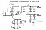
This simple device, the circuit diagram of which is shown in Fig. 1, is designed to control the AC mains voltage of 220 V. The device can take its rightful place in an amateur radio mini-laboratory or find application in the refinement of various industrial household equipment.
Fig.1. Scheme of a mains voltage voltmeter with an extended scale
As a prototype, the author's device was used, the description of which can be found on the pages of the Electrician magazine. The proposed device, in addition to the function of indicating the mains voltage with a pointer microammeter, has the ability to inform the operator about a significant excess of the mains voltage with an intermittent sound signal. This simple node can also be used to refine devices for automatically disconnecting consumers of electricity from the network, increasing their functionality.
The device is powered by a 220 V AC mains. The excess energy of the mains voltage is quenched by a high-voltage film capacitor C1, then the reduced voltage is fed through the current-limiting resistor R4 to a half-wave voltage rectifier made on the VD2 diode and HL1-HL3 LEDs. The rectified voltage is limited by the thermally compensated zener diode VD3, and the ripple of the rectified voltage is filtered by the oxide capacitor C4.
The device works as follows. The mains voltage through the rectifier diode VD1 and the limiting resistor R1 is supplied to the rectified voltage filter capacitor C2. The voltage to which this capacitor is charged is almost directly proportional to the mains voltage. It is desirable to make the scale of a small-sized microammeter to display the value of the mains voltage stretched, for example, by placing on it the most important section with values of 180 ... 250 V.
Transistor VT1 operates as a micropower microcurrent zener diode with a stabilization voltage of about 40 ... 50 V. As long as the voltage at its junction is less than the reversible avalanche breakdown voltage, this transistor is closed, the voltage at the VT2 gate terminal relative to the common wire is almost zero, VT2 is closed, the PA1 microammeter readings are minimal . The transistor VT3 will also be closed.
When the voltage at the emitter junction VT1 becomes greater than the threshold, this transistor will open, and the source follower on VT2 will open, the microammeter needle will deviate. The greater the mains voltage, the greater the angle the arrow deviates from the initial position. In the event that the mains voltage significantly exceeds the permissible limit, for example, 260 V, the voltage at the output of the source follower on VT2 is sufficient to open the p7-channel field effect transistor VT3. As a result, the flashing HL4 LED flashes, in time with its flashes, a sound piezoceramic emitter with a built-in HA1 generator beeps. The threshold for turning on the sound alarm is set by adjusting the tuning resistor R9. The green LEDs HL1–HL3, in addition to their function of rectifying the mains voltage, illuminate the scale of the device.
Details. Resistor R4 is desirable to use non-flammable R177 or similar imported discontinuous. The remaining fixed resistors are any small-sized ones, for example, C174, MLT, C2723, C2733. Trimmer resistors SP471, RP1763, SP3738 or similar small imported ones. After the final adjustment of the device, it is desirable to replace the tuning resistors with constant ones, which will increase the long-term accuracy of the meter setting. Capacitor C1 for an operating voltage of at least 630 V. Domestic polyethylene terephthalate K73717, K73724, K73739 are suitable. Also, as C1, you can use a pair of series-connected imported capacitors of the GPF 250V ~ X2 type with a capacity of 0.47 uF. Capacitor C3 is any small-sized ceramic, and C4 is an imported analogue of K5035.
Diodes 1N4004 can be replaced by any of the series KD209, KD243G-Zh, KD247V-D, KD105B-G. Zener diode D818G can be replaced by any of this series or KS482A, KS510A, KS191M, D814B. The use of a zener diode in a miniature glass case is undesirable. LEDs HL1-HL3 can be replaced by almost any with a permissible forward current of 20 mA, visible color of the glow, for example, KIPD66D7L, KIPD24ZH7L, AL307N7M. Flashing LED HL4 can be replaced by any of the series L56B, L36B, L796B and others.
Bipolar transistors of the KT501 series are not quite ordinary, they allow a relatively high base-emitter voltage. Without significant adjustment of the resistance of the resistor R2, transistors KT501Zh-KT501M can be used. In the absence of such or a similar transistor, a 30 ... 50 V microcurrent zener diode can be made from several transistors of the KT315, KT312 types. Field-effect transistors KP501B are interchangeable with any of this series or KP504, KP505, K1014KT1, ZVN2120.
The author used an M4761 type microammeter with a frame resistance of about 900 ohms, taken from an old faulty domestic Saturn reel-to-reel tape recorder. Other similar microammeters from recording / playback level indicators are also suitable. The use of a field effect transistor as VT2 makes the previously set settings (except for adjusting R7) practically independent of the type of dial indicator used. The piezoceramic sound emitter can be replaced by EFM7473, EFM7475, EFM7250 consuming low current.

Fig.2. Circuit board sketch
Setting up the device comes down to setting the required sensitivity of the device and the “stretching” of its scale, which is achieved by selecting and adjusting the resistances of resistors R2, R3, R5, R7. Resistor R10 can be set to the desired volume of the sound emitter signal HA1. A sketch of the printed circuit board is shown in Figure 2.
Literature
1. Butov A.L. Voltmeter of mains voltage with an extended scale//Elektrik. - 2002. - No. 7. – P.14.
2. Butov A.L. Mains voltage control device//Circuit engineering. - 2003. - No. 2. - P.44.
A.L. Butov, Yaroslavl region
Radioamator 2005 №08
The device will be useful for motorists to measure the voltage on the battery with high accuracy, but it can also find other applications where it is required to control the voltage in the range of 10 ... 15 V with an accuracy of 0.01 V.
Rice. 1 Extended scale voltmeter
It is known that the degree of charge of a car battery can be judged by its voltage. So, for a fully discharged, half-discharged and fully charged battery, it corresponds to 11.7, 12.18 and 12.66V.
In order to measure the voltage with such accuracy, you need either a digital voltmeter, or a pointer with an extended scale, which allows you to control the interval of interest to us.
The scheme shown in fig. 1, allows, using any microammeter with a scale of 50 μA or 100 μA, to make a voltmeter from it with a measurement scale of 10 ... 15 V.
The voltmeter circuit is not afraid of incorrectly connecting the polarity to the measured circuit (in this case, the readings of the device will not correspond to the measured value).
To protect the microammeter PA1 from damage during transportation, the switch S1 is used, which, when shorting the leads of the measuring device, prevents the needle from fluctuating.
The circuit uses a PA1 device with a mirror scale, type M1690A (50 μA), but many others are also suitable. Precision zener diode VD1 (D818D) can be with any last letter in the designation. Trimmer resistors are best used multi-turn, for example R2 type SPZ-36, R5 type SP5-2V.
To set up the circuit, you will need a power supply with an adjustable output voltage of O ... 15 V and an exemplary voltmeter (it is more convenient if it is digital). The setting consists in connecting the power supply to the terminals X1, X2 and gradually increasing the voltage to 10 V, to achieve the "zero" position of the arrow of the PA1 device with resistor R5. After that, we increase the voltage of the power source to 15 V and, with the resistor R2, set the arrow to the limit value of the scale of the measuring device. On this setting can be considered complete.

Rice. 2. Circuit for more accurate measurement of mains voltage
Based on this scheme, the device can be made multifunctional. So, if the microammeter conclusions are connected to the circuit through a 6P2N switch, you can make a regular voltmeter mode by choosing an additional resistor, as well as a tester for checking circuits and fuses.
The device can be supplemented with a circuit (Fig. 2) for measuring alternating mains voltage. In this case, it will have a scale from 200 to 300 V, which allows you to more accurately measure the mains voltage.
List of radio elements
| Designation | A type | Denomination | Quantity | Note | Score | My notepad | |
|---|---|---|---|---|---|---|---|
| VD1 | zener diode | D814D | 1 | To notepad | |||
| R1, R3, R4 | Resistor | 270 ohm | 3 | 1 watt | To notepad | ||
| R2 | Trimmer resistor | 100 kOhm | 1 | To notepad | |||
| R5 | Trimmer resistor | 2.2 kOhm | 1 | To notepad | |||
| PA1 | Microammeter | M1690A | 1 | To notepad | |||
| S1 | switch | 1 | To notepad | ||||
| VD1-VD4 | Diode | KD243J | 4 | To notepad | |||
| R1 | Resistor | 12 kOhm | 1 | 2 watt | |||
And although we have long been accustomed to digital voltmeters, pointer meters are still found in nature.
In some cases, their use may be more convenient and practical than the use of modern digital ones.
If a pointer voltmeter fell into your hands, then it is advisable to find out its main characteristics. They are easy to identify by the scale and the inscriptions on it. I got my hands on a built-in voltmeter M42300.

Below, under the scale, as a rule, there are several icons and the model of the device is indicated. So, the icon in the form of a horseshoe (or a curved magnet) means that this is a device of a magnetoelectric system with a movable frame.
In the next picture you can see such a horseshoe.

The horizontal dash indicates that the meter is designed for direct current (voltage) operation.
Here it is worth clarifying why we are talking about direct current. It's no secret that not only voltmeters are pointer, but also a huge number of other measuring instruments, for example, the same analog ammeter or ohmmeter.
The action of any pointer device is based on the deflection of the coil in the field of the magnet when a direct current passes through this very coil. To display the readings on the scale of the instrument with the help of an arrow, the current must be constant.
If it is variable, then the arrow will deviate to the right and left with the frequency of the alternating current that flows through the coil winding. To measure the magnitude of alternating current or voltage, a rectifier is built into the measuring device.
That is why, under the scale of the device, the type of current with which it is able to work is indicated: direct or alternating.
Further on the scale of the device, you can find an integer or fractional number, like 1,5 ; 1,0 and the like. This is the accuracy class of the instrument, expressed as a percentage. It is clear that the smaller the number, the better - the readings will be more accurate.
You can also see such a sign - two intersecting lines at a right angle. This symbol indicates that the instrument is in a vertical working position.
In a horizontal position, readings may be less accurate. In other words, the device can "lie". It is better to install a pointer voltmeter with such an icon vertically into the device and exclude a significant inclination.
But such a sign indicates that the working position of the device is horizontal.
Another interesting sign is a five-pointed star with a number inside.
This sign warns that the voltage between the device body and its magnetoelectric system must not exceed 2 kV (2000 volts). It is worth paying attention to this when operating a voltmeter in high-voltage installations. If you plan to use it in a 12 - 50 volt power supply, then you should not worry.
How to read readings from the scale of a pointer voltmeter?
For those who see the scale of the device for the first time, a quite reasonable question arises: "But how to read the readings?" At first glance, nothing is clear.
In fact, everything is simple. To determine the minimum division of the scale, you need to determine the nearest number (number) on the scale. As we can see on the scale of our M42300, this is 2.

Next, we count the number of spaces between the lines up to the first number or number - in our case, up to 2. There are 10 of them. Then we divide 2 by 10, we get 0.2. That is, the distance from one small dash to the next is 0.2 volts.
Here we have found the minimum division of the scale. Thus, if the arrow of the device deviates by 2 small divisions, then this will mean that the voltage is 0.4V ( 2*0.2V=0.4V).
Practical example.
In the presence of the already familiar built-in voltmeter model M42300. The device is designed to measure DC voltage up to 10 volts. The measurement step is 0.2 volts.
We fasten two wires to the terminals of the voltmeter ( observe polarity!), and connect a dead 1.5 volt battery or any one that comes across.

These are the readings I saw on the scale of the device. As you can see, the battery voltage is 1 volt ( 5 divisions * 0.2V = 1V). While photographing, the voltmeter needle stubbornly moved to the top of the scale - the battery gave out the last "juices".


It turned out that the current consumed by the pointer voltmeter was only 1 milliamp ( 1 mA). It is enough for the arrow to deviate to the full scale. This is very little. Let me explain my point.
It turns out that the pointer voltmeter is more economical than the digital one. Judge for yourself, any digital measuring device has a display (LCD or LED), a controller, as well as buffer elements to control the display. And that's just part of his scheme. All this consumes current, sits down a battery or accumulator. And if in the case of a voltmeter with a liquid crystal display, the current consumption is small, then with an active LED indicator, the current consumption will already be significant.
So it turns out that for portable self-powered devices it is sometimes more reasonable to use a classic pointer voltmeter.
When connecting a voltmeter to a circuit, there are a few simple rules to keep in mind.
Firstly, a voltmeter (any, even digital, even pointer) must be connected in parallel with the circuit or element, the voltage on which it is planned to measure or control.
Secondly, the operating range of measurements should be taken into account. It is easy to recognize it - just look at the scale and determine the last number on the scale. This will be the boundary voltage for measurement by this voltmeter. Naturally, there are also universal voltmeters, with a choice of measurement limit, but now we are talking about a built-in pointer voltmeter with one measurement limit.
If you connect a voltmeter, for example, with a measurement scale of up to 100 volts, to a circuit where the voltage exceeds these 100 volts, then the arrow of the device will go off scale, "go off scale". This state of affairs will sooner or later lead to damage to the magnetoelectric system.
Thirdly, when connecting, it is worth observing the polarity if the voltmeter is designed to measure direct voltage. As a rule, the terminals (or at least one) indicate the polarity - plus "+" or minus "-". When connecting voltmeters designed to measure alternating voltage, the polarity of the connection does not matter.
I hope that now it will be easier for you to determine the main characteristics of a pointer voltmeter, and most importantly, to use it in your homemade products, for example, by embedding it in a power supply with an adjustable output voltage. And if you make the LED backlight of its scale, then it will look generally gorgeous! Agree, such a pointer voltmeter will look stylish and impressive.
Something about measurements
1.1. Expansion of measurement limits for ammeters and voltmeters. Pointer (electromechanical) ammeters and voltmeters contain a measuring mechanism (micro- or milliammeter), a measuring transducer: shunts or additional resistors to expand the measurement limits and a rectifier system, if the measurement of alternating currents and voltages is provided. Measuring mechanisms of the magnetoelectric system are most widely used in pointer electromechanical devices. The main characteristics of some of them are given in Table. one.
Table 1
Magnetoelectric system meters
The expansion of the current measurement limit is carried out by connecting the shunt in parallel with the meter. In multi-limit instruments, it is more convenient not to have an individual shunt for each measurement limit, but the so-called universal shunt. In this case, simple sockets, clamps or a conventional switch can be dispensed with, while with individual shunts, the desired measurement limit can only be selected using a special transfer switch. Otherwise, at the moment of switching, the measuring mechanism (milli- or microammeter frame) is under multiple current overload with all the ensuing consequences.

Rice. 1. Scheme of a multirange ammeter with a "universal" shunt.
To expand the measurement limit of the meter P (Fig. 1) by current N times (I 1 = NI n), a shunt with resistance is required:

where r is the internal resistance of the meter.
The components of the shunt resistance are determined by the formulas:
Voltage measurement limit extension carried out by including an additional resistor in series with the meter. Schemes of multi-limit voltmeters are shown in fig. 2. The resistance of each additional resistor for the voltmeter shown in fig. 2, a, is determined by the formula:

where U is the selected measurement limit; I and - the current of the total deflection of the arrow of the meter; r - internal resistance of the meter.
For a voltmeter made according to the circuit shown in Fig. 2, b, the resistance of additional resistors is calculated by the formulas:
etc. for each subsequent measurement limit.

Rice. Fig. 2. Scheme of a multi-limit voltmeter with separate additional resistors (a) and with composite ones (b).
In voltmeters of a low accuracy class, the use of non-wire resistors is permissible. Moreover, it is more convenient to make each additional resistance out of two resistors. This makes it easier to provide the required resistance. For example, 327.91 kOhm can be obtained by selecting a pair of resistors with the desired resistance deviation from the nominal value, from resistors with a nominal resistance of 330 kOhm (20 or 10% series) and 910 Ohm (5% series).
Appliances containing a rectifier system , allow you to measure voltages and currents with frequencies up to several tens of kilohertz with a practically uniform scale, with the exception of a small area at its beginning. The measured alternating currents and voltages are converted by semiconductor rectifiers into a direct current recorded by a magnetoelectric meter. The rectifier system can be made according to a half-wave or two-half-wave (bridge) scheme.

Rice. Fig. 3. Scheme of the meter with one-half-wave (a) and two-half-wave (b) rectifier system and current graphs.
In a half-wave circuit (Fig. 3, a), the resistor R serves to equalize the resistance of the rectifying part for currents in both directions, and its resistance is chosen equal to the internal resistance of the meter r. When measuring a sinusoidal current with an effective value of I, the average rectified value of the current that deflects the meter needle, I срв 0.45 I. Therefore, at the current of the total deviation of the meter I and the limiting effective value of the alternating current measured by the rectifier part of the device will be:
In a full-wave circuit (Fig. 3, b), a higher sensitivity is obtained. In this circuit, the P meter is included in the diagonal of the bridge formed by four diodes. Here, the current passes through the meter in both half-cycles in the same direction. Therefore, the average rectified value of the current I srv 0.9 I, and the limiting value of the measured current I p 1.11 I and. The disadvantage of a full-wave circuit compared to a single-half-wave circuit is that the uneven area at the beginning of the scale expands somewhat due to a decrease in the voltage applied to each diode. In practical circuits, instead of two adjacent diodes (for example, VD1 and VD2 or VD3 and VD4), resistors with a resistance of several thousand ohms are sometimes included. Although this worsens the sensitivity of the device, it increases the temperature stability and improves the uniformity of the scale.
The scales of the instruments of the rectifier system are calibrated in the effective values of the sinusoidal current (clauses 1.23, 1.24). If the shape of the curve of the measured current differs from a sinusoid, then an error occurs, depending on the shape factor of the curve kφ \u003d I / I cv (see, for example, paragraph 1.26).
In the manufacture of a voltmeter (ammeter) of the rectifier system, it is necessary to know the data of its rectifier part: total deviation current I n, total deviation voltage U n and nominal resistance to alternating current rn \u003d U n / I n, which can be determined empirically by analogy with the method described in pp. 1.2 and 1.3.
1.2. Measuring the internal resistance of a microammeter can be done by connecting it to a power source through a variable resistor. By changing the resistance of the resistor, such a current I p is set so that the arrow of the device deviates to the full scale. Next, the device is shunted with a resistor with resistance Rsh so that the current I flowing through the device is about half the total deviation current I p.
If the resistance of the frame r (internal resistance of the microammeter) is much less than the additional resistance (the included part of the variable resistor), then the total current in the circuit after connecting the shunt to the device will not change significantly and the current through Rsh can be considered Ish \u003d I p - I. Since at parallel connection rI \u003d R w I w, then the resistance of the device frame can be calculated by the formula: r \u003d R w (I p / I - 1).
The use of resistance R W with a deviation from the nominal value of ± 5% gives a measurement error that is quite acceptable in amateur practice.
1.3. Measuring the input resistance of a voltmeter can be carried out using a power source, the internal resistance of which is negligible compared to the input resistance of the voltmeter. Such a source can be a rectifier, a “fresh” battery or a cell, a charged battery.
The input resistance of a voltmeter, especially a tube or transistor voltmeter, is usually quite large. Such a voltmeter, connected to the battery, will show the value of the battery EMF (E). To improve the accuracy of measurements, it is desirable to choose the voltage of the power source and the measurement limit of the voltmeter so that the arrow deviates almost to the full scale. After that, a resistor is connected between the voltage source and the input of the voltmeter, the resistance of which R is known with sufficient accuracy. Due to the voltage drop across this resistor, the voltmeter reading decreases to the value U. Now the input resistance of the voltmeter can be determined by the formula:

Voltmeters (separate or included in the ampere-voltmeter), in which additional resistors switch when moving from one measurement limit to another, have different input resistance at different measurement limits. Such devices are usually characterized by the input resistance, referred to one volt of the scale limit. This resistance for a given voltmeter is unchanged at all limits.
1.4. Features of measuring direct voltages are that the connection of a voltmeter leads to a decrease in the total resistance of the circuit section, in parallel to which the voltmeter is connected. The relative decrease in resistance is determined by the ratio R c / (R in + R c), where R c is the total resistance of the circuit between the switching points of the voltmeter, and R in \u003d R ext + R and \u003d U p / I and is the input resistance of the voltmeter. The voltmeter will have little effect on the circuit mode at R in » R c. This condition is not always fully met in practice, therefore, on diagrams of industrial designs of equipment, on voltage maps, in mode tables, not only the values, but also the type of device by which they are measured are often indicated. When measurements must be carried out in very high-resistance circuits, and even more so when the connection of a voltmeter significantly affects the mode of the studied cascade, it is recommended to use an electronic voltmeter with a much higher input resistance.
1.5. Features of direct current measurement due to the fact that the device is connected in series in the circuit under study. This leads to an increase in the total resistance of the circuit and a decrease in the current in it. The device will have the less influence on the circuit mode, the smaller the voltage drop across it in comparison with the voltage acting in the circuit.
If a pulsating or pulsed current flows in the circuit under study, then the magnetoelectric device will respond to the DC component of this current as well. In this case, a high-capacity capacitor is connected in parallel with the device, which has a much lower resistance for the variable current component than the meter itself. In addition, the place of switching on the device in a circuit with a variable component is chosen in such a way that one of its terminals is connected directly or through a large capacitor to the case.
1.6. Current measurement with a voltmeter especially convenient if for some reason it is undesirable or technically difficult to break the circuit to turn on the ammeter. In this case, the voltage drop across the resistor through which the measured current passes is measured. If the resistance of the resistor is known (or specially measured), then the desired current is determined according to Ohm's law: I \u003d U / R, where I is the current, mA; U - voltmeter reading, V; R is the resistance of the resistor, the voltage drop across which was measured with a voltmeter, kOhm. It must be remembered that the resistance of the voltmeter should be at least 10-20 times higher than the resistance of the resistor on which the voltage drop is measured.
1.7. Features of measuring alternating voltages and currents in circuits where there is also a constant component, it primarily consists in the fact that the magnetoelectric device with a rectifier system also responds to this component. Another thing is an electronic measuring device with a closed input, i.e. having an input capacitor connected between the input terminal and the device circuit. However, an amateur does not always have such a device.
By measuring alternating voltages with a conventional ampere-voltmeter, you can eliminate the influence of the constant component if you connect the device to the measured circuit through a capacitor of a sufficiently large capacity. The capacitance should be such that the resistance of the capacitor at a given frequency would be much less than the input resistance of the voltmeter. For example, for the lower part of the audio frequency range with an input resistance of a voltmeter of 20 kOhm / V, a 1 μF capacitor can be used. For higher frequencies, the capacitance of the capacitor can be reduced. At the same time, it must be remembered that with increasing frequency, the frequency error of the voltmeter also increases, since the readings of the device begin to depend not only on the active resistance, as when measuring direct voltages, but also on the reactance, i.e. from the total resistance of the device. Here, the reactance is primarily due to the presence of loop inductances, additional resistors (especially wire ones) and other factors.
It is more convenient to measure alternating currents in debugged circuits using the voltmeter method (section 1.6).
When measuring alternating voltages or currents, it is important to choose the right place for connecting the device to the circuit under study. It is desirable to turn on the device so that the potential of the connection point of the device is as close as possible to the "ground" potential, and even better if one of the probes is grounded.
© "Encyclopedia of Technologies and Methods" Patlakh V.V. 1993-2007