Olga 13546
You will probably be surprised, but an ordinary CRT TV is still in fairly stable demand.
It may seem incredible to you, but sometimes it also happens that if you understand the advantages of a CRT TV, then the idea of \u200b\u200bbuying one, even for you, will not become a crazy thought. You can buy a new CRT TV, and sometimes you even need to. CRT TVs are still sold by many companies around the world, as well as in our country and in every city. You can buy a CRT TV both in a regular store and on the Internet.
I’ll tell you right away about the advantages of a CRT TV.
 |
Store77 | 33 990 Р | |
 |
compyou.ru | 18 510 R | |
 |
Store77 | 17 990 Р |
Not to mention the price of such a device, which, of course, is an order of magnitude, or even somewhat lower than modern sophisticated models, we note that the technology for the production of kinescopes is so well developed by time that there are simply no surprises and accidents during their production and assembly, as a result always get a flawless and high-quality product.

Further, the image quality, unlike the possible deviations from the norm in expensive models, is excellent and the color reproduction is natural (the newest panels have deviations that are not so easy to adjust).
The service life of a CRT TV is tens of years (of course, under conditions of correct, normal operation). Surely you know that even "Soviet" TVs in some houses work quite well to this day. What can we say about modern CRT models, with details worked out to the smallest detail - I think legends will form about their service life)))
The viewing angle of a CRT TV is practically unlimited (of course, if you are not trying to watch a movie from its back). The picture, which you look at even from the side, does not lose color and quality, it does not fade compared to a modern flat panel.
 |
Store77 | 35 990 Р | |
 |
compyou.ru | 8 250 R | |
 |
LG TV LCD 43" 43LJ515V black | Electrozon | 22 990 Р |
Modern models of CRT TVs have the necessary connectors for connecting modern accompanying equipment - disc players, karaoke systems, satellite dishes and other devices necessary for today's user.
Of course, a CRT TV has its drawbacks.
The first is a flickering image, which is not very good for your eyesight. Unfortunately, this shortcoming for the kinescope is uncorrectable.
Magnetic radiation, although it is reduced to a minimum in the modern model, is still there, and it also does not give health to the owner.
Disposing of such a TV also requires some gestures. It just cannot be thrown into the trash, but it is advisable to take it to a specialized institution.

And, of course, the dimensions. The thickness of a CRT TV is its most “fat” minus, so to speak, and today not everyone is ready to keep such a “fatty” in their home. Although their dimensions are reduced to the smallest possible, a CRT TV cannot be so thin that it can be hung like a picture on the wall.
 |
Nowadays, even a child knows what a TV is and uses it all the time. Technology is constantly improving, CRT TVs are becoming a thing of the past. They are being replaced by liquid crystal monitors, as well as LED technologies.
Nevertheless, we will focus on CRT TVs, because many continue to use them for certain reasons. They are also called CRT.
Device
If you get very close to a CRT TV, you will find that the picture on its screen consists of miniature dots. They flicker, burn brighter or dim. If you move away, what is happening on the screen is perceived as a moving picture. This is due to the ability of the human brain to collect everything into a single whole.
The screens of kinescope TVs are shaped like a pear. In place of the "shank" is the so-called electron gun, which directs the electron streams on the screen. The screen surface is filled with phosphor dots. This is a substance that glows when an electric beam hits it. From these smallest points, the whole picture is formed on the screen of kinescope TVs.
Where does color come from?
The screen of a color kinescope TV is even more complicated. On it, phosphors have different properties and glow green, blue and red. All other colors are obtained by mixing these three.
The electron beam shoots rapidly at the screen and impacts the phosphor dots 25 times per instant. As a result, the human eye sees a moving image. Electric beams "run" through all the lines on the screen in the shortest moments.

Specifications
CRT TVs differ in technical parameters:
- Screen size. The larger it is, the larger the TV itself. This means that the largest TV can not fit in all rooms. If the dimensions of the room are modest, the technique must also be chosen small. The smallest TV has a diagonal of 10 inches. Popular models with diagonals from 14-15 inches, as well as 20-25. The largest are 29- and 34-inch. When choosing a screen, you should determine in advance the location of the device in the room. A mandatory requirement is the presence of space between the housing and the wall. Otherwise, the equipment will quickly fail.
- Screen Format. Usually 4:3 is used. 16:9 widescreen is preferred for watching movies. TVs also have auto aspect ratio.
- The scan, or rather its frequency, indicates the quality of the image. In previous models, it was equal to 50 Hz, so the viewer had the feeling that the picture was constantly flickering. Later the frequency was increased to 100-120 Hz.
- Speakers. In small models, they are usually built in, large-sized options have stereo speakers.
- Connectors for connecting devices. Models that are produced today are already equipped with more than just antenna connectors. As a rule, they have audio and video outputs to which you can connect video and DVD equipment.

Advantages and disadvantages
The advantages of CRT TVs are:
- affordable cost;
- variety of choice of models;
- excellent picture quality;
- color realism;
- long service life.
The disadvantages of technology include:
- large dimensions;
- negative impact on the organs of vision during prolonged viewing.

Image problems
Consider the most common malfunctions of CRT TVs:
- Blurred image on the screen. This is due to a broken kinescope. During the repair, the master can perform an additional winding on the transformer, but in the future it will be necessary to change the screen. If a bright glow with thin horizontal streaks appears on the screen, such a kinescope cannot be restored.
- The screen is off. This occurs when a filament breaks or a shorted cathode is detected. With such a malfunction, the master checks for the presence of a circuit between the contacts. If there is no circuit, the screen cannot be restored. In another case, the master solders the contacts and fixes the breakdown.
- Image offset. In this case, the incidence of rays on the phosphor is disturbed. You can try tapping a rubber object around the edges, but most often you have to change the kinescope.

Typical defects of some models
There are also typical defects in some models. For example, in Samsung kinescope TVs, the power supply often burns out. The master changes the mains fuses. It is also possible that the image is disturbed due to a malfunction of the thermistor, it is changed to a new one.
If the TV suddenly smokes, you need to turn it off and urgently call the master. Usually the cause of the breakdown is swollen capacitors, which are replaced with serviceable ones.
Erisson TVs may not transition from standby to working over time. This is due to the fact that the kinescope burn protection is activated in the device if there is a breakdown in the frame scanning nodes. Replacing a faulty transistor with a working one can help.
The LG CRT TV is prone to another breakdown. Over time, it may not turn on. The master will inspect and check:
- Are the capacitors good?
- are there any microcracks in the board and power circuit;
- whether there was a detachment of contacts.
If breakdowns are detected, the master eliminates them, and the equipment pleases its owner with a working condition.
Of course, the repair of CRT TVs should be entrusted to professionals. In this case, you can be sure of the quality of the service, and the TV will last more than one year.
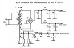
Based on the MS-994A chassis, the following TV models are produced: CA-14/20/21 F89W, CA-14/20/21 F89X, CF-2O/21 D79, CF-2O/21 F39, CF-14/20/21 F69X, CF-14/20/21 F89, CF-14/20/21 F89W, CF-14/20/21 F89X. The main technical characteristics of these models are presented in Table. one.
Design and features of the MS-994A chassis
Structurally, the chassis consists of the main board, the kinescope board, the "EYE" board (see Table 1) and the teletext module. The last two nodes are optional. The main feature of the new chassis is the use of a TOSHIBA TB1238AN multifunctional IC501 chip containing an IF, a video detector, an audio demodulator, a video processor, a sync processor and an I 2 C interface circuit. Its use greatly simplified the chassis circuitry, which, in turn, led to an increase TV reliability.
Table 1. The main technical characteristics of LG TVs based on the MS-994A chassis
| Characteristic | Description |
|---|---|
| Screen diagonal, inch | 14, 20, 21 |
| Color television systems | PAL, SECAM, NTSC 4.43 (NTSC 3.58 - from LF input) |
| TV standards | D/K, B/G, I, M |
| Received frequency range, MHz | VHF-L: 46.25...168.25 VHF-H: 172.25...463.25 UHF: 471.25...863.25 |
| Number of memorized programs | 100 |
| Additional functions | EYE (automatic adjustment of image parameters depending on the illumination); timer on/off; sleep timer; child lock; switching the image format (Standart, Wide, Zoom); camera mode (not on all models) |
| Nutrition | AC mains 100...270 V, 50 Hz |
| Power consumption, W | up to 95 |
| Sound | monophonic |
| Audio channel output power, W | 5 |
| Antenna input impedance, Ohm | 75, asymmetrical |
The chassis control system is based on an IC01 microcontroller (MC) of the MC37221 type from MITSUBISHI, which is paired with an IC02 non-volatile memory chip of the 24С04 type. To exchange data between microcircuits and transmit commands to the IC501 microcircuit, the MK uses the I 2 C digital interface.
A feature of the new chassis is the presence of an interface for a video camera that allows you to use the TV, in particular, as a monitor for a video surveillance system.
In table. 2 shows the parameters of replaceable elements depending on the diagonal of the kinescope screen.
Table 2. Parameters of replaceable elements depending on the diagonal of the kinescope screen
| Positional designation | Denominations and types of elements | ||
|---|---|---|---|
| Kinescope 14" | Kinescope 20" | Kinescope 21" | |
| FR401 Ohm | 2,4 | 5,4 | 1,4 |
| IC804 | SE110N | SE110N | SE115 |
| ТН801 | 163-054F | 163-012C | 163-O12C |
| R303, Ohm | 5,6 | 4,7 | 3,9 |
| R304, Ohm | 5,6 | 4,7 | 3,9 |
| R309 Ohm | 5,1 | 5,1 | 1,2 |
| R311, Ohm | 1,5 | 1.5 | 4,7 |
| R405, Ohm | 82 | 47 | 47 |
| R407, kOhm | 12 | 12 | 10 |
| R410, kOhm | 130 | 100 | 100 |
| R905, Ohm | 390 | 330 | 330 |
| R913, Ohm | 33 | 39 | 27 |
| R915 Ohm | 390 | 330 | 330 |
| R922 Ohm | 390 | 330 | 330 |
| R924 Ohm | 470 | 270 | 270 |
| S402, pf | 180 | 180 | 390 |
| С412, uF | 0,39 | 0,33 | 0,36 |
| С414, pf | 7300 | 7300 | 7300 |
| S902, pf | 330 | 560 | 560 |
| С904, pF | 470 | 330 | 330 |
| S907, pf | 270 | 560 | 560 |
Let's consider the operation of the main chassis components and the paths for the passage of audio and video signals, as well as the main elements of their processing.
Power Supply
The power supply unit (PSU) generates stabilized voltages +115 (V+), +20 (S-VCC), +14, +12, +9 and +5 V (ST-5V) to power the chassis nodes in operating and standby modes. It is built according to the scheme of a quasi-resonant flyback converter on an IC803 chip of the STR-F6707 type from SANKEN. The IC803 includes: a master oscillator, start-up circuits, overload protection, overvoltage and overtemperature protection, as well as an output stage based on a powerful bipolar transistor. The microcircuit turns on when the voltage on the pin. 4 is about 8.5 V, and turns off at a voltage of 5 V and consumes a current of 30 mA in operating mode, and 200 μA in standby mode. Circuit R809 R810 generates a trigger voltage, and obm. 1-2 T802 and a rectifier on the elements D806, C801 - supply voltage in operating mode. The output voltages are stabilized by the IC804 IC801 feedback circuit, the input of which (pin 11C804) is connected to the B + bus, and the output is connected to the input of the error signal amplifier of the IC803 controller (pin 1). To control the current limit through the power switch of the transmitter (R805), the voltage drop is removed and fed to the pin. 11C803 (protection level is about -0.9 ... -1.2 V). Using transistor keys Q805-Q807 and optocoupler IC802 MK signal with pin. 5 switches the PSU to standby mode. In this case, the converter operates at the minimum operating frequency.
The circuit on the elements R807, C831, Q831, Q832 generates an ABNORMAL alarm on the MK (pin 6) in case of malfunctions in the output circuits of the B + bus or in the horizontal scanning circuit. Secondary voltages +5 and +9 V are formed by integrated regulators IC805 and IC844, the latter being controlled. The IC844 chip is controlled by the MK ON / OFF signal (pin 5).
Image tract
The television radio signal from the antenna input is fed to the input of the TU101 tuner, which is controlled by the MK (pin 31, 33 IC01) via the I2C interface (pin 4, 5 TU101). The tuner is powered by 5 V (pin 7). The output signal of the tuner (pin 11) with an IF equal to 38 MHz, through a band-pass filter Z101, which forms the frequency response of the IF path, is fed to the input of the IF - pin. 6 and 7 chips IC501. Here are its main functions:
- generating a composite color video signal (CVBS) from the PHI signal;
- formation of an audio signal from the PCHZ signal;
- AGC voltage generation for the tuner;
- automatic detection of the color system and decoding of PAL and NTSC systems;
- control of external SECAM decoder (IC502);
- extracting the luminance signal from the CVBS;
- formation from color difference signals: luminance signal and primary colors (RGB);
- switching RGB signals and on-screen menu (OSD), their amplification to the level required to control the output video amplifiers on transistors Q901-Q903;
- extraction of sync pulses from CVBS and generation of horizontal and sawtooth trigger pulses for vertical scanning control;
- reception and processing of control commands from the MC via the I 2 C interface.
The pin assignment of the TB1238AN chip is shown in Table. 3.
Table 3. Purpose of the pins of the TB1238AN chip
| Output number | Signal | Description |
|---|---|---|
| 1 | DE-EMP | audio signal output to attenuator |
| 2 | AUDIO OUT | Audio signal output |
| 3 | IFVCC | Analog supply voltage 9 V |
| 4 | AFT OUT | AFC signal output |
| 5 | ID GND | General |
| 6 | IF IN | IF signal input |
| 7 | IF IN | IF signal input |
| 8 | RF AGC | AGC voltage for tuner |
| 9 | IF AGC | AGC voltage for IF |
| 10 | APC FILTER | Auto Image Adjustment Filter |
| 11 | X-TAL | Quartz resonator 4.43 MHz |
| 12 | Y/C GND | Common luma and chrominance channels |
| 13 | Ys/Ym | HALF TONE control input |
| 14 | OSD R | OSD signal input R |
| 15 | OSD G | OSD G signal input |
| 16 | OSD B | OSD signal input B |
| 17 | RGB VCC | Video processor supply voltage 9 V |
| 18 | R OUT | R signal output |
| 19 | G OUT | Signal output G |
| 20 | B OUT | Signal output B |
| 21 | ABCL | Input of dimming and beam current limiting circuits |
| 22 | V RAMP | Capacitor HPN vertical scan |
| 23 | V NFB | OH pulse input |
| 24 | V OUT | Vertical ramp sawtooth output |
| 25 | V AGC | Vertical AGC filter |
| 26 | SCL | Interface clock bus I 2 C |
| 27 | SDA | Interface data bus I 2 C |
| 28 | H. VCC | Horizontal oscillator supply voltage 9 V |
| 29 | ID/SW OUT | SECAM signal switching output |
| 30 | FBP IN | Login SIOH |
| 31 | SYNC OUT | Synchronization signal output |
| 32 | H.OUT | Horizontal Trigger Output |
| 33 | DEF. GND | General |
| 34 | SCP OUT | SCP Bilevel Gating Output |
| 35 | VIDEO SW | CVBS video output for SECAM decoder |
| 36 | DIG VDD | Power supply for the digital part of the circuit (5 V) |
| 37 | SECAM B-Y | signal input SECAM B-Y |
| 38 | SECAM R-Y | SECAM R-Y signal input |
| 39 | Y-IN | Brightness input Y |
| 40 | H. A.F.C. | AFC filter 1 |
| 41 | EXT YIN | Video switcher input 1 |
| 42 | DIG. GND | Common digital part of the circuit |
| 43 | TV IN | Video Switcher Input 2 |
| 44 | BLACK DET | Black Area Extender Filter |
| 45 | WITH IN | External color signal input |
| 46 | Y/C VCC | Video processor supply voltage 5 V |
| 47 | DET OUT | Video detector output |
| 48 | LOOP FILTER | Connecting an AGC filter |
| 49 | GND | General VCO |
| 50 | VCO | VCO Reference Loop |
| 51 | VCO | VCO Reference Loop |
| 52 | VCC | Supply voltage 9V VCO |
| 53 | LIM IN | FC signal input |
| 54 | RIPPLE FILTER | Smoothing filter |
| 55 | EXT AUDIO IN | External audio input |
| 56 | FM DC NF | Audio path power filter |
The video processor switch input (pin 14-16 of IC501) can receive OSD-R, G, B, TXT-R/G/B teletext signals, or external SCART-R/G/B signals. The selection of the necessary signals is carried out by the IC751 switch, controlled by the FB-ID signals (pin 39 of IC01), TXT-FB (pin 8 P701B) or SCART-FB (pin 16 PJ201). Output video signals of primary colors with pin. 18,19, 20 IC501 via cont. 2, 4 and b of the P901V connector go to the transistors of the Q901-Q903 output video amplifiers, which are powered by 180 V from the horizontal scanning circuit. In addition, through contact 1 P901B bias voltage of 12 V is applied to the video amplifiers, which determines the operating points of the transistors. There are no adjusting elements of video amplifiers in the circuit because all adjustments are made by the IC501 video processor in the service mode using the MK via the I 2 C interface.
Sound path
The main part of the audio path is in the IC501 chip. To isolate sound signals of various standards, an IC151 switch with filters F151-F154, controlled by MK signals: SO, S1 and M4.5 (pin 38, 39, 14), is used. The PCR signal from the video detector output (pin 47 of IC501) is fed through the Q507 buffer to the inputs of the F151-F154 filters connected to the IC151 switch. The output signal of the PCHZ with vyv. 3 IC151 is input to the demodulator - pin. 53 IC501. The audio output from the demodulator is amplified and fed to the INT/EXT switch (inside IC501) to select the appropriate signal. External sound signal on the output. 55 IC501 comes from SCART or cinch connectors. The audio signal source selected by the IC01 microcontroller via the I 2 C interface is removed from the pin. 2 IC501 and is fed to the input of the audio frequency power amplifier (UMZCH) - pin. 5 of the IC601 chip of the TDA7253 type, which is a single-channel push-pull class AB amplifier with short circuit protection and a MUTE mute input (pin 3). From its output (pin 8), the signal through the isolation capacitor C605 and connector P601 is fed to the dynamic head. UMZCH is powered by a 20 V power supply (S-VCC).
Teletext module
A teletext module can be installed on the MC-994A chassis, which is connected via connectors P701B, P702B. The basis of the module is an IC701 chip of the SAA5281 type, which has an 8 Kx8 RAM for 8 teletext pages. It is designed to work with the 625-line WST (World System Teletext) standard. It also decodes VPT (VCR Programming) signals. It is controlled by the MK via the I2C interface (pin 24, 25). For IC701 to work on its pin. 9 with IC501 (pin 35) the TXT-CVBS video signal is received. At the outputs of the microcircuit, teletext signals R, G, B (pin 16, 17.18) and a blanking (strobe) signal TXT-FB (pin 20) are generated, which are fed to the IC751 switch, and from it to the IC501 video processor.
To power the teletext module on the cont. 3 P701V is supplied with 9 V from the power supply. IC701 is powered by 5V from IC702.
Horizontal and vertical scan nodes
The line scan is built according to the usual two-stage circuit (transistors Q401, Q402) with a series-powered output stage. Transistor Q401 is powered by 14 V, and Q402 is supplied by +115 V (V+) from the power supply. The output transistor has an internal snubber diode. The line transformer T402 forms the supply voltage of the kinescope, vertical scanning (24 V) and output video amplifiers (180 V). All T402 secondary circuits are protected against overload by breaking resistors FR301, FR401 and FR501.
On the capacitor C418, a voltage is formed that is inversely proportional to the current of the kinescope rays. The signal ABL (EX) from the output of the shaper is fed to the pin. 21IC501 to control dimming and beam current limiting circuits.
The vertical scan output stage is implemented on the IC301 chip of the LA7833 type from SANYO. The sawtooth vertical scan pulses are fed to the input of the microcircuit (pin 4) from the pin. 24 IC501. To the output of the microcircuit (pin 2) the personnel coils of the OS V-DY are connected. To control and stabilize the vertical size, the V-NFB feedback signal is removed from the amplifier output and fed to the pin. 23 IC501.
As already noted, the IC301 chip is powered by 24 V (pin 6) from the horizontal scanning circuit.
To synchronize the OSD circuit, the horizontal (pin 10 T402) and vertical (pin 7 IC301) sweep pulses are fed to the MK through inverters Q01, Q02 (pin 1 and 2).
microcontroller
MK IC01 performs the function of managing all chassis nodes. The operation of the MK is provided by the X01 quartz resonator (vyv. 19, 20), the IC03 reset circuit and the IC02 non-volatile memory. The purpose of the pins of the microcircuit is presented in Table. 4.
Table 4. Purpose of the pins of the IC01 chip
| Output number | Signal | Purpose |
|---|---|---|
| 1 | H-SYNC | Horizontal sync input |
| 2 | V-SYNC | Vertical sync input |
| 3 | LED | Output to LED indicator |
| 4 | CC/AV ID | Source identification input "camera/LF input" |
| 5 | POWER | Power supply control output |
| 6 | ABS | Alarm input |
| 7 | MNT-CTL | Switching sound to SCART (TV/AV) |
| 8 | DEGAUSE | Kinescope degaussing output |
| 9 | EYE | Light sensor input |
| 10 | IR-IN | Photodetector signal input |
| 11 | SD IN | Video presence identification input |
| 12 | TURBO | Tuner tuning mode switch output |
| 13 | TBS-SW | Tuner AGC time constant switch output |
| 14 | 4.5M | Standard M |
| 15 | S-MUTE | Mute output (not used) |
| 16,18,21 | GND | General |
| 17 | FS | Service mode switch input |
| 19 | X-IN | Quartz resonator 8 MHz |
| 20 | X-OUT | Quartz resonator 8 MHz |
| 22 | VCC | Supply voltage +5 V |
| 23 | 0SC2 | Generator output 1 (not used) |
| 24 | 0SC1 | Generator input 1 (not used) |
| 25 | RESET | Reset input |
| 26 | AFT | Tuner Fine Tuning Control Input |
| 27 | AGC | AGC voltage input |
| 28 | F8 ID | Blanking pulse input from SCART |
| 29 | KEY1 | Keyboard scan input 1 |
| 30 | KEY2 | Input 2 keyboard scan |
| 31 | SDA1 | I2C interface data bus |
| 32 | CCTV-CTL | TV/Camera switch output |
| 33 | SCL1 | Pc Interface Synchronization Bus |
| 34 | CCTV ID | CCTV signal identification input |
| 35 | Ym | Switch output "1/2 image brightness" |
| 36 | MELODY | Audible information output |
| 37 | 51 | TV switch output 1 |
| 38 | SO | Output 2 TV switch |
| 39 | Output of blanking pulses OSD | |
| 40-42 | B-G-R | OSD circuit video outputs |
Service mode
As in any modern television receiver, the adjustment elements of the RF path, video processor and other components on the MC-994A chassis that are necessary after repair or replacement are performed in the service mode. To work in this mode, you must have a remote control with teletext control buttons. Before making adjustments, turn on the TV, apply the "Test table" signal to its antenna input and warm it up for 15 ... 20 minutes.
To enter the service mode, simultaneously press the "OK" buttons on the remote control and on the front panel of the TV, holding them until the list of adjustable parameters appears on the screen (Fig. 1). The last line "LINE SVC 0" shows the menu number, and there are five in total (LINE SVC 0-4).
Rice. 1. List of adjustable parameters in service mode
The required parameter is selected with the up-down joystick buttons, and its value is adjusted with the left-right buttons. To save the new parameter value, press the "OK" button. To exit the service mode, put the TV into standby mode using the "Power" button on the remote control. Consider the sequence of adjustments of the main parameters on the MS-994A chassis.
RF AGC adjustment
This adjustment is mandatory after replacing the tuner, as well as when significant noise (interference) appears in the image.
- Connect a voltmeter to the output. 1 tuner TU101.
- The signal "Color Polo" is fed to the antenna input of the TV from the TV signal generator.
- sy" with a level of 65 dB, turn on and set the TV to receive this signal, and then switch it to service mode.
- Select the "AGC" parameter in the menu and adjust it until the voltmeter reads 2.3 V for the 6700VPV002A tuner or 3.0 V for the 6700VPV002B tuner. The "OK" button remembers the new value of the "AGC" parameter.
Adjustment of accelerating voltage
Accelerating voltage, as a rule, is adjusted after replacing the kinescope or after repairing the horizontal scanning circuit.
- Served on the antenna input of the TV signal "Color bars" from the generator of television signals.
- In service mode, select the menu "LINE SVC 3", and in it - the parameter "CUTOFF".
- The Screen regulator on the T402 transformer ensures that the light horizontal line is barely visible.
White balance adjustment
This operation must be performed after adjusting the accelerating voltage.
- The signal "White field" is applied to the antenna input of the TV and the contrast control is set to the maximum, and the brightness is set to 90% of the maximum position.
- In service mode, select the "LINE SVC 0" menu.
- By adjusting the "GG" and "BG" parameters, the white balance is achieved in "light".
- Set the brightness and contrast controls so that the screen barely glows, and adjust the "RC", "GC" and "BC" parameters to achieve the white balance in "dark".
- If necessary, repeat the adjustment several times, achieving the optimal balance.
- white.
The factory values of the parameters are given in Table. 5.
Table 5. Factory settings for white balance adjustment
| Parameter | factory values |
|---|---|
| RC | 125 |
| GC | 140 |
| sun | 125 |
| GG | 58 |
| BG | 65 |
Focus adjustment
This operation is performed in the same cases as the previous one, as well as when the focus deteriorates. Turn on the TV, apply the signal "Grid" or "Test table" to its antenna input and warm up for 15 ... 20 minutes. Then, with the Focus knob on the horizontal transformer, the best image focusing is achieved.
Image geometry adjustment
This adjustment is made as needed.
- The same signal is fed to the antenna input of the TV as in the previous case.
- Before adjusting, use the "ARC" button on the remote control to select the "STANDARD" image format.
- Enter the service mode, and in it - select the "UNESVC2" menu.
- Select the parameters "VL" (vertical linearity), "VS" (vertical centering), "VA" (vertical dimension), "HS" (horizontal centering), "SC" (S-correction) in succession and adjust the geometry Images.
Setting options
Adjusting the options is necessary in order to configure a specific TV model. The options are set in the "OPTION 1" and "OPTION 2" menus.
Table 6
| Option | The code | Function |
|---|---|---|
| SHI SYSTEM | 0 | BG standard only (CA- models) |
| 1 | BG + TAI DUAL (Asia) | |
| 2 | BG + 1 + DK (no NTSC 3.58, CF-, CZ- models) | |
| 3 | BG + DK + M (with NTSC 3.58, models CT-, CD-) | |
| CCTV | 0 | Without CCTV |
| 1 | With CCTV system | |
| SCART | 0 | Phone Jack or Carnera-in Jack only |
| 1 | There is a top scart jack | |
| 4 key | 0 | 6 front panel buttons (MENU, OK, VOL-, VOL+, PR-, PR+) |
| 1 | 4 front panel buttons (TV/AV, ROTATE, PR-, PR+) | |
| EYE | 0 | Without Eye System |
| 1 | With Eye System | |
| TOP | 0 | Teletext banned |
| 1 | Teletext allowed | |
| H-TONE | 0 | OSD on blue background |
| 1 | Halftone background for OSD |
Options and their possible values are given in table. 6 and 7.
Table 7
| Option | The code | Function | Microcontroller version |
|---|---|---|---|
| LANG | 00 | Multilingual Support | - |
| 01 | English only | ||
| 10 | Two languages | ||
| LANG-INDEX | 0 | English | LG8993-27A/B |
| 1 | Countries of the former USSR | ||
| 2 | Chinese | ||
| 3 | Romanian | ||
| 4 | Polish | ||
| 0 | English | LG8993-28A | |
| 1 | French | ||
| 2 | Indian | ||
| 3 | Arab | ||
| 4 | Urdu | ||
| 5 | Persian | ||
| 0 | English | LG8993-29A | |
| 1 | Indonesian | ||
| 2 | Malay | ||
| 3 | Vietnamese | ||
| 4 | Thai | ||
| CURVE | 0 | Rapid increase in volume | - |
| 1 | Slow volume up | ||
| TBS | 0 | TBS function disabled | - |
| 1 | TBS function enabled | ||
| HOTEL | 0 | Function disabled | - |
| 1 | Function allowed |
Typical malfunctions and solutions
The TV does not turn on, the "POWER" indicator does not light up, the mains fuse F801 blows
Disconnect the TV from the mains and use an ohmmeter to check for a short circuit the elements of the demagnetization circuit, surge protector, rectifier: ТН801, ТН802, С806-С810, VD801, Т801, RT801, RT802, DB801. If there is no short circuit in these circuits, then the power transistor (pins 2 and 3 of IC803) is checked for a short circuit with an ohmmeter. If these elements are in good order, the T802 transformer is unsoldered and checked according to one of the well-known methods.
The TV does not turn on, the "POWER" indicator does not light up, the mains fuse F801 is OK
Turn on the TV with the SW801 power switch and measure the voltage +300 8 at the pin. 3 IC803. If the voltage is zero, then the elements of the following circuit are checked for an open: F801, SW801, T801, R811, DB801, pin. 8-5 T802, FB803, pin. 3 IC803. If the voltage is 300 V at the pin. 3 is present, but the converter does not work (there are no pulses with a swing of about 500 V on pin 3 of IC803), then they check the external elements of the microcircuit that provide its power in start-up and operating modes (see description).
If the converter is working (there are pulses on pin 3 of IC803), check the 5 V regulator (IC805). If it is serviceable, then check the MK and its external elements (see description and table. 4).
The "POWER" indicator is lit, the TV is in standby mode and does not switch to work
First of all, the ON / OFF signal is checked (pin 5 of IC01). If the signal is high (i.e. the TV is in standby mode), the power supply's B+ channel streaming overload protection may have been activated.
In this case, the ABNORMAL signal on pin. 5 IC01 will be active (low level). Turn off the TV and determine the cause of the B + channel overload. If the protection signal is passive, the MCU itself may be faulty or IC02 memory may have failed. The microcircuit is rewritten and, if the TV still does not turn on, the MK is replaced. If the ON / OFF signal (pin 5 of IC01) is low, the Q807 switch must be closed and the 9V regulator (IC844) turned on.
There is no raster and sound, the power supply is working
Perhaps one of the voltages on the kinescope board and the kinescope itself is missing: HV, USCREEN, UHEATER. 180 V. Check the presence of the specified voltages, determine the missing and eliminate the cause. If there is no high voltage (there is no characteristic crackling when the TV is turned on and off), then most likely the reason is in the horizontal scanning circuit. Check the presence of trigger pulses on the pin. 32 IC501, their entry into the preliminary stage on the Q401 transistor and the operation of the output stage on the Q402 transistor (there should be positive polarity pulses on the collector with a swing of about 1000 V). If the output stage does not work, disconnect the TV from the network and check all its external elements. If there are pulses, but there is no high voltage, the reason is in the horizontal transformer T402.
There is a raster, there is no sound and image
First, the IF path and the video processor (IC501 chip) are checked. The power supply of the microcircuit is controlled (see Table 3). If there is no supply voltage of 5 V (pin 46), check the IC505 stabilizer. If the power supply is normal, a test signal with a frequency of 38 MHz with a level of 65 dB is applied to the input of the IF path (pin 11 of the TU101 tuner) and the passage of the signal along the path is monitored (see description and osc. 1, 3-5). Identify and replace faulty items. In the absence of a test generator, a VCR or a video camera connected to the corresponding inputs can be used as a signal source, but in this case only the video processor is tested.
No color image in SECAM color system
Most likely, the IC502 chip or its external elements are faulty. Set the saturation control to the maximum level. They check the power supply of the microcircuit (5 V on pins 9 and 18. If there is no voltage, they check the stabilizer on the elements ZD504, R531), the presence of a video signal on the pin. 13 and 15 IC502, strobe pulses on the pin. 17, all external capacitors. If the elements are working, replace the chip.
TV only works on bass input
Check the power of the tuner A101 (33 and 5 V). Then a test signal is fed to the antenna input of the tuner from the generator, the auto-tuning mode is turned on and the corresponding control signals are checked at the tuner outputs (see description). If there are signals, but the output signal IF (range 0.25 ... 0.5 V) is absent, replace the tuner.
No sound
They check the power supply of the IC601 chip (20 V on pin 9) and the absence of a blocking signal (high potential on pin 3), the health of the dynamic head and the presence of a contact in the P601 connector. Then they touch the pin with a metal object (for example, tweezers). 5 IC601. If a background appears in the dynamic head, then the UMZCH is working. Otherwise, replace the chip.
There is no sound when receiving TV programs
Check the presence and passage of the sound signal through the following circuit: pin. 47 IC501, Q507, Q151, F151-F154, pin. 1, 2, 4, 5 IC151, pin. 3 IC151, pin. 53 IC501, pin. 2 IC501. Identify and replace the failed path element.
No sound or picture when working through LF input
Check the corresponding paths.
Video path: PJ201, C251, pin. 7, 8 IC251, pin. 41IC501.
Audio path: PJ201, C227, Q221, pin. 10.11 IC251, C257, pin. 55 IC501.
TV does not respond to remote control commands
Faulty remote control. First, install known good batteries in the remote control. To check, use an IR range photodiode, for example, FD-8K, connect its outputs to the oscilloscope input, direct the remote control to the photodiode and press one of the remote control buttons. On the oscilloscope screen there should be bursts of pulses with an amplitude of about 0.5 V. If they are not there, they check the health of the elements of the remote control circuit: microcircuit, resonator, output transistor and LED.
If the remote control is working, press one of the buttons on the remote control and check for a signal with an amplitude of 4 ... 4.5 V on the pin. 1 RA01. If there is no signal, then replace the photodetector. If there is a signal, the microcontroller IC01 is faulty.
The image is dominated by one of the colors, the black and white image has a color tint of the same color
As a rule, this happens due to a change in the parameters of the radio elements and the kinescope due to their aging. To eliminate, adjust the white balance in the service mode (see "Service mode").
A thin horizontal line is visible on the TV screen
Check the sawtooth pulses (osc. 9) on the pin. 24 IC301. If they are not there, they check the capacitor C313 (osc. 6) and all the elements in the feedback circuit: C308, R314, R313, R306, R407, C301.
If the sawtooth pulses on the pin. 4 IC301 is, and the output signal on pin. 2 is missing (the signal span is about 45 ... 50 V), check the power supply of the microcircuit (24 V on pin 6) and the following elements: R303, R304, C311, R310, C310, V-COIL If they are working, replace the microcircuit IC301.
The vertical size of the image is small and cannot be adjusted in service mode
Check the elements of the voltage boost circuit D302 and C307.
Although cathode ray tube televisions are outdated and are gradually losing their positions in the modern market, there is often no alternative to them.
The most expensive part of such TVs is a kinescope, the quality of the picture shown on the screen directly depends on the correct operation of it. The correctness and duration of the operation of the kinescope depends on the mode and conditions of its operation. It is important to ensure that the voltage on the kinescope electrodes corresponds to the specified technical parameters.
If problems arise in the operation of the kinescope, then it is most prudent to ask for help from a qualified craftsman, since careless handling of it can not only completely disable the device, but also seriously injure a person with high voltage.
If you decide to find the problem yourself, then the procedure should be as follows:
- Check the reliability of the contact on the kinescope board. To do this, carefully shake the kinescope board, carefully monitoring the changes in its operation. Try not to damage the leads on the kinescope base.
- Check the serviceability and reliability of the connection of the anode input.
- Check the focus wire.
The most common malfunctions of the kinescope and its circuits:
- Breakage of the filament in the cathode heating system;
- Termination of electron emission from one or more electron gun cathodes;
- Partial or complete loss of vacuum by the kinescope;
- Closure of electrodes of the electron gun;
- color distortion;
- Loss of contact between the second anode and the kinescope.
Signs that the kinescope is out of order:
- The screen has completely stopped glowing;
- The screen barely glows;
- Only one of the primary colors of the triad is displayed on the screen;
- The screen does not display any of the primary colors.
Let's look at some of the signs of typical kinescope malfunctions, as well as the alleged causes of their occurrence.
The screen does not light up, although the soundtrack is on
In this case, we can assume:
- If the kinescope filament does not light up, and the necessary voltage of 6.3 V is present at its terminals, then the contact with the board is broken. You should check the contacts between the pins of the kinescope 1 and 14 or 9 and 10 (in different models of kinescopes) with an ohmmeter "for an open" after removing the board from it.
- If voltage is not applied to the kinescope electrodes, then there is damage in the filament circuit.
- If the filament glows, then the problem is in the poor adjustment of the kinescope operating modes. You should make sure that the voltage between the modulators and cathodes of the kinescope, which changes with a change in the brightness level, is within the specified limits (do not exceed 100-120 V). In addition, it is necessary to check the potential on the control electrodes (from 400 to 500 V).
The screen glows, but not bright enough, while the signals of the desired level are supplied to the modulators
The orientation of the magnets of the beam convergence system (color purity) is broken. In some types of kinescopes, it is possible to achieve a high-quality and bright display of a television picture by rotating the magnets on the neck.
The screen glows with only one of the primary colors, and it is impossible to adjust its brightness
Most likely, there was a short circuit between the modulator and the cathode of the gun, the color of which is lit on the screen. Another reason may be a malfunction of the video amplifier of the color that prevails on the screen.
The screen lights up, but one of the primary colors is not displayed on it
The problem is created by a broken cathode or a complete loss of the electron gun emission responsible for the missing color on the screen.
Choosing a CRT TV
A cathode ray kinescope (also called a cathode ray tube, CRT) is a technology that has come down to us from the last century. Serial production of the first televisions that worked on this principle began back in 1939. Nevertheless, such a venerable age of this technology is rather its advantage than a disadvantage, because CRT TVs are still used today, which means that they fully satisfy the needs of those who like to spend their free time at blue screens. So in this case, the condescending phrase “last century” does not mean “junk” at all, but time-tested traditions.
In our time, the most widely used, the most "advanced" consumers already have an idea about the principles of operation of these devices. But some potential buyers are unaware of what is inside the case of a CRT TV.
The device and principle of operation of a kinescope TV
As mentioned above, the main element of an old-style TV is a cathode ray kinescope (in the English version of Cathode Ray Tube, CRT). In this device, the process of forming a television “picture”, which is then displayed on the screen, takes place.

In the figure, the numbers indicate:
1 - electron guns (three for color TVs, one for black and white);
2 - electron beams;
3 - focusing coils;
4 - deflecting coils;
5 - anode output;
6 - shadow "mask", filtering out the red, green and blue parts of the "picture";
7 - a layer of phosphorus-containing phosphor covering the inner surface of the screen, with areas of red, green and blue glow;
8 is an enlarged view of the phosphor coating on the inside of the screen.
In fact, a cathode ray tube is a glass bulb, inside which a vacuum is created. Under the influence of electricity, electron guns (1) begin to emit rays (2) that pass through the kinescope tube. These beams, which are directed electron flows, are captured by a system of focusing and deflecting coils (3, 4). Electromagnetic coils redirect the beams to the anode terminal (5), which supplies electrons to the filter mask (6), which separates the total stream into color components. In the oldest models of black and white TVs, the color filter, of course, was absent.
The process of appearance of the image on the screen can be described as follows. After the formation and filtering of the light fluxes, the rays fall on the inner surface of the television screen (7), which is invisible to the audience. The phosphor coating consists of red, green and blue particles that glow when exposed to a beam of the corresponding color. The surface covered with a phosphor is not fully illuminated, only individual particles of the substance are illuminated - thus, the rays sent by the anode output form a rapidly moving light spot on the screen. This spot moves across the screen line by line, from left to right and from top to bottom, but the movement is very fast, imperceptible to human eyes, so the viewer sees a complete image. Accordingly, the higher the screen refresh rate (the period of “running” of the light spot from the first to the last point), the better the image is obtained.
The kinescope tube is located perpendicular to the screen surface, which means that it takes up a lot of space under the TV case. That is why the case of such a device has such impressive dimensions and it is impossible to make it super-thin, like modern plasma or LCD TVs, for purely technological reasons. It is not surprising that kinescope devices have received a tender nickname among the people - "boxes"!

The main technical characteristics of kinescope TVs
Now that we have a general idea of the operation of the kinescope, we can begin to choose a TV. In principle, the main parameters to be guided by when choosing are quite obvious. However, inexperienced buyers may not pay attention to enough technical details that spoil all the pleasure of watching your favorite series or an important sports match.
1. Screen size and shape
When purchasing a “window” into the vast world of television, it is important not to miscalculate with the size, otherwise you will not be able to see much. Obviously, TVs with the largest screen sizes are large, so owners of small living rooms will have to moderate their appetites. In CRT TVs, as the screen size increases, not only the height and width increase, but also the depth of the case, which means that relying on a large screen, the unlucky buyer may face a big problem: the new thing will take up too much free space in the room.
The smallest CRT TVs have a diagonal of 10 inches - viewing programs on them cannot be called comfortable. The optimal minimum is 14-15 inches; TVs with such parameters are produced by almost all well-known companies. Screens with a diagonal of 20 to 25 inches are even more popular. TVs with such dimensions fit perfectly into an average apartment and, as a rule, have a complete set of the most requested functions. The largest are 29-inch CRT TVs, but models with a 34-inch screen can also be found on sale. These are real giants, they are suitable only for very large rooms and are usually installed on special cabinets supplied as a set or by order.
When choosing a TV, it is important to remember such a parameter as the most comfortable viewing distance.

Based on this table, it is easy to determine the approximate location of furniture in the living room seating area, namely, the distance at which the TV stand and the sofa or chairs should be spaced apart. When purchasing a CRT TV, it is necessary to plan in advance the place of its installation. If it will stand in a furniture niche, then a prerequisite is the presence of a gap between the walls of the niche and the body of the device, while air access to the ventilation openings must not be blocked. Otherwise, the TV will overheat and fail.
The screen size is also important. With a classic width-to-height ratio of 4:3, it's best to watch regular TV shows. Wide screens with a 16:9 aspect ratio are ideal for watching movies, so if the TV will be paired with a DVD player most of the time, widescreen is preferable. There are several other less popular formats that allow you to get an image with minimal distortion. Modern TV models have an automatic format adjustment function.
Screen ratio
The sharpness of the image depends on the geometry of the screen. A convex kinescope distorts the “picture” quite strongly. To get the most realistic images, it is better to purchase a TV with a flat or super flat screen.
2. Sweep frequency is one of the indicators of image quality. In accordance with the principle of operation of the kinescope described above, the image on the screen appears due to the glow of phosphor particles. It is the sweep frequency that determines the speed at which the light spot moves across the screen. In older TVs, this figure was 50 Hz, so it seemed to the viewer that the “picture” was flickering. When watching TV for a long time, the unstable image caused severe eye fatigue. Modern kinescopes provide a refresh rate of 100-120 Hz - this indicator is considered optimal for large-screen TVs, where image instability is especially noticeable.
It should be noted that at a screen refresh rate of 100 Hz, the effect of a loop from objects moving quickly in the frame is sometimes observed. To stabilize the "picture" manufacturers use special technologies. When purchasing a large-sized TV, you should pay attention to image stabilization technology: for Digital Plus, for Digital Scan Natural Motion, for Super Digital, for Digital Mastering or Intelligent Mastering, depending on the model.
3. Speakers
Television programs are not only a visual range, so powerful and high-quality sound is one of the main technical characteristics. Small TVs are often equipped with single speakers, while large models are equipped with only stereo speakers. Regardless of the number of speakers, they are always located on the front surface of the case, usually below or on the sides of the screen.
Standard speaker layout below the screen (left) and on the sides of the screen (right)
Expensive modern CRT televisions often have built-in subwoofers that transmit low-frequency sound, and surround sound systems made using Dolby Pro Logic or Dolby Digital technology.
4. Connectors for connecting external devices
As you know, a TV cannot work on its own; it needs an external antenna or a digital cable to receive a signal. Perhaps, among modern TVs it is impossible to find a single model that would be equipped only with an antenna connector. For full use, you also need, at a minimum, audio and video outputs, to which you connect a VCR and DVD player.
Minimum set of connectors: TV antenna jack and RCA connectors for audio and video signals
In addition, the set of connectors will not be superfluous analog VGA port and universal SCART port - you can connect multimedia equipment, satellite or digital receiver to it.
5. TV control method
The remote control has long been an invariable attribute of the TV. This simple and easy-to-use device allows you to change channels, adjust the volume level and perform many other tasks without getting up from the couch. Nevertheless, on the front panel of the TV, as a rule, you can find the main control buttons that duplicate the corresponding keys on the remote control, usually these are the power button, volume controls and channel navigation buttons.
Control buttons located on the TV case
When choosing a TV, you should not buy such a model, on the body of which the entire set of control panel buttons would be duplicated - such a device would be too bulky. Only the main keys are enough, which can be used if the batteries are dead in the remote control.
Advantages and disadvantages of CRT TVs
Since we have already dealt with the main technical characteristics of CRT TVs, it is also necessary to consider the strengths and weaknesses of these devices.
Advantages:
- low price;
- a wide variety of models;
- good image quality;
- realistic color reproduction;
- long service life (about 15 years).
Flaws:
- large dimensions and weight;
- negative impact on vision during prolonged viewing.