Since I assembled a CNC machine for myself a long time ago and have been using it regularly for hobby purposes for a long time, I hope my experience will be useful, as well as source codes controller.
I tried to write only those points that I personally found important.
The link to the controller sources and the configured Eclipse+gcc shell, etc. are located in the same place as the video:
History of creation
Regularly faced with the need to make one or another small “thing” of a complex shape, I initially thought about a 3D printer. And he even started doing it. But I read the forums and assessed the speed of the 3D printer, the quality and accuracy of the result, the percentage of defects and the structural properties of thermoplastic, and I realized that this is nothing more than a toy.The order for components from China arrived within a month. And after 2 weeks the machine was working with LinuxCNC control. I assembled it from whatever crap I had at hand, because I wanted to do it quickly (profile + studs). I was going to redo it later, but, as it turned out, the machine turned out to be quite rigid, and the nuts on the studs did not have to be tightened even once. So the design remained unchanged.
Initial operation of the machine showed that:
- Using a 220V “china noname” drill as a spindle is not a good idea. It overheats and is terribly loud. The lateral play of the cutter (bearings?) can be felt by hand.
- The Proxon drill is quiet. The play is not noticeable. But it overheats and turns off after 5 minutes.
- A borrowed computer with a bidirectional LPT port is not convenient. Borrowed for a while (finding PCI-LPT turned out to be a problem). Takes up space. And generally speaking..
Why people still stubbornly torment 8-bit ATMega for relatively complex tasks, and even through Arduino, is a mystery to me. They probably love difficulties.
Controller development
I created the program after thoughtfully reviewing the LinuxCNC and gbrl sources. However, I did not take either of the sources for calculating the trajectory. I wanted to try to write a calculation module without using float. Exclusively on 32-bit arithmetic.The result suits me for all operating modes and I haven’t touched the firmware for a long time.
Maximum speed, selected experimentally: X: 2000 mm/min Y: 1600 Z: 700 (1600 step/mm. mode 1/8).
But it is not limited by controller resources. It’s just that the disgusting sound of skipping steps even on straight sections through the air is higher. The budget Chinese stepper control board on the TB6560 is not the best option.
In fact, I don’t set the speed for wood (beech, 5mm depth, d=1mm cutter, step 0.15mm) to more than 1200 mm. The likelihood of cutter failure increases.
The result is a controller with the following functionality:
- How to connect to an external computer standard usb mass storage device (FAT16 on SD card). Working with standard G-code format files
- Deleting files via user interface controller.
- View the trajectory of the selected file (as far as the 640x320 screen allows) and calculate the execution time. In fact, emulation of execution with time summation.
- View the contents of files in test form.
- Manual control mode from the keyboard (moving and setting “0”).
- Start execution of a task using the selected file (G-code).
- Pause/resume execution. (sometimes useful).
- Emergency software stop.
After creative experiments in cutting out hand-drawn reliefs on wood, and experiments with acceleration settings in the program, I also wanted additional encoders on the axes. Just on e-bay I found relatively cheap optical ecocoders (1/512), the division pitch of which for my ball screws was 5/512 = 0.0098 mm.
By the way, the use of optical encoders high resolution, without a hardware circuit for working with them (the STM32 has it) is pointless. Neither interrupt processing, nor, especially, software polling will ever cope with the “bounce” (I’m saying this for ATMega fans).
First of all, I wanted for the following tasks:
- Manual positioning on the table with high precision.
- Control of missed steps with control of deviation of the trajectory from the calculated one.
However, I found another use for them, albeit in a rather narrow task.
Using encoders to correct the trajectory of a machine with stepper motors
I noticed that when cutting out a relief, when setting the Z acceleration to more than a certain value, the Z axis begins to slowly but surely creep down. But, the time for cutting relief with this acceleration is 20% less. Upon completion of cutting out a 17x20 cm relief with a step of 0.1 mm, the cutter can go down 1-2 mm from the calculated trajectory.
Analysis of the situation in dynamics using encoders showed that when lifting the cutter, 1-2 steps are sometimes lost.
A simple step correction algorithm using an encoder gives a deviation of no more than 0.03 mm and reduces processing time by 20%. And even a 0.1 mm protrusion on wood is difficult to notice.
Design

I considered it an ideal option for hobby purposes. desktop version with a field slightly larger than A4. And this is still enough for me.
Movable table
It still remains a mystery to me why everyone chooses a design with a movable portal for tabletop machines. Its only advantage is the ability to process a very long board in parts or, if you have to regularly process material that weighs more than the weight of the portal.During the entire period of operation, there was never a need to cut out a relief piece by piece on a 3-meter board or engrave on a stone slab.
The movable table has the following advantages for tabletop machines:
- The design is simpler and, in general, the structure is more rigid.
- All the internals (power supplies, boards, etc.) are hung on a fixed portal and the machine turns out to be more compact and more convenient to carry.
- The weight of the table and a piece of typical material for processing is significantly lower than the weight of the portal and spindle.
- The problem with cables and spindle water cooling hoses practically disappears.
Spindle
I would like to note that this machine is not for power processing. The easiest way to make a CNC machine for power processing is on the basis of a conventional milling machine.In my opinion, a machine for power processing of metal and a machine with a high-speed spindle for processing wood/plastics are absolutely different types equipment.
At the very least, it makes no sense to create a universal machine at home.
The choice of a spindle for a machine with this type of ball screw and guides with linear bearings is straightforward. This is a high speed spindle.
For a typical high-speed spindle (20,000 rpm), milling non-ferrous metals (steel is out of the question) is an extreme mode for the spindle. Well, unless it’s really necessary and then I’ll eat 0.3 mm per pass with watering the coolant.
I would recommend a water-cooled spindle for the machine. During operation, you can only hear the “singing” of the stepper motors and the gurgling of the aquarium pump in the cooling circuit.
What can be done on such a machine?
First of all, I got rid of the housing problem. The body of any shape is milled from “plexiglass” and glued together with a solvent along ideally smooth cuts.
Fiberglass has become a universal material. The precision of the machine allows you to cut out a seat for the bearing, into which it will fit cold, as expected, with a slight tension, and then cannot be pulled out. Textolite gears are perfectly cut with an honest involute profile.
Wood processing (reliefs, etc.) is a wide scope for the realization of one’s creative impulses, or, at a minimum, for the realization of other people’s impulses (ready-made models).
I just haven’t tried the jewelry. There is nowhere to calcinate/melt/cast the flasks. Although a block of jewelry wax is waiting in the wings.
Among the wide variety of controllers, users are looking for those circuits that will be acceptable and most effective for self-assembly. Both single-channel and multi-channel devices are used: 3- and 4-axis controllers.
Device options
Multi-channel stepper motor controllers (stepper motors) with standard sizes of 42 or 57 mm are used in the case of a small working field of the machine - up to 1 m. When assembling a machine with a larger working field - over 1 m, a standard size of 86 mm is needed. It can be controlled using a single-channel driver (control current exceeding 4.2 A).
A machine with numerical control, in particular, can be controlled by a controller created on the basis of specialized driver chips intended for use for stepper motors up to 3A. The CNC controller of the machine is controlled by a special program. It is installed on a PC with a processor frequency of over 1 GHz and a memory capacity of 1 GB). With a smaller volume, the system is optimized.
NOTE! Compared to a laptop, if you connect a desktop computer, you get better results, and it’s cheaper.
When connecting the controller to a computer, use a USB or LPT parallel port connector. If these ports are not available, then expander boards or controller converters are used.
Excursion into history
The milestones of technological progress can be schematically outlined as follows:
- The first controller on the chip was conventionally called the “blue board”. This option has disadvantages and the scheme required improvement. The main advantage is that there is a connector, and the control panel was connected to it.
- Following the blue one, a controller called the “red board” appeared. It already used fast (high-frequency) optocouplers, a 10A spindle relay, power isolation (galvanic) and a connector where the fourth axis drivers would be connected.
- Another similar device with red markings was also used, but more simplified. With its help, it was possible to control a small desktop type machine - one of the 3-axis ones.
- The next in the line of technological progress was a controller with galvanic isolation for power supply, fast optocouplers and special capacitors, having an aluminum housing that provided protection from dust. Instead of a control relay that would turn on the spindle, the design had two outputs and the ability to connect a relay or PWM (pulse width modulation) speed control.
- Now, for the manufacture of a homemade milling and engraving machine with a stepper motor, there are options - a 4-axis controller, a stepper motor driver from Allegro, a single-channel driver for a machine with a large working field.
IMPORTANT! Do not overload the motor by using higher and higher speeds.

Controller made from scrap materials
Most craftsmen prefer control via the LPT port for most amateur-level control programs. Instead of using a set of special microcircuits for this purpose, some people build a controller from scrap materials - field effect transistors from the burnt motherboards(at a voltage of over 30 volts and a current of more than 2 amperes).
And since a machine for cutting foam plastic was created, the inventor used car incandescent lamps as a current limiter, and the SD was removed from old printers or scanners. This controller was installed without changes to the circuit.
To make a simple CNC machine with your own hands, by disassembling the scanner, in addition to the SD, the ULN2003 chip and two steel rods are removed, they will go to the test portal. In addition you will need:
- A cardboard box (from which the device body will be mounted). An option with textolite or plywood sheet is possible, but cardboard is easier to cut; pieces of wood;
- tools - in the form of wire cutters, scissors, screwdrivers; glue gun and soldering accessories;
- board option that is suitable for a homemade CNC machine;
- connector for LPT port;
- a cylinder-shaped socket for arranging a power supply;
- connection elements - threaded rods, nuts, washers and screws;
- program for TurboCNC.
Assembling a homemade device
Having started working on a homemade CNC controller, the first step is to carefully solder the chip onto breadboard with two power buses. Next will be the connection of the ULN2003 output and the LPT connector. Next, we connect the remaining pins according to the diagram. The zero pin (25th parallel port) is connected to the negative pin on the board's power bus.
Then the motor is connected to the control device, and the power supply socket is connected to the corresponding bus. To ensure the reliability of the wire connections, they are fixed with hot glue.
Connecting Turbo CNC will not be difficult. The program is effective with MS-DOS and is also compatible with Windows, but in this case some errors and failures are possible.

Having configured the program to work with the controller, you can make a test axis. The sequence of actions for connecting the machines is as follows:
- Steel rods are inserted into holes drilled at the same level in three wooden blocks and secured with small screws.
- The SD is connected to the second bar, putting it on the free ends of the rods and screwing it using screws.
- The lead screw is threaded through the third hole and a nut is installed. The screw inserted into the hole of the second bar is screwed in until it stops so that it passes through these holes and comes out onto the motor shaft.
- Next, you need to connect the rod to the engine shaft with a piece of rubber hose and a wire clamp.
- Additional screws are required to secure the running nut.
- The made stand is also attached to the second block using screws. The horizontal level is adjusted with additional screws and nuts.
- Typically, motors are connected along with the controllers and tested to ensure correct connections. This is followed by checking the CNC scaling and running a test program.
- All that remains is to make the body of the device and this will be the final stage of the work of those who create homemade machines.

When programming the operation of a 3-axis machine, there are no changes in the settings for the first two axes. But when programming the first 4 phases of the third, changes are introduced.
Attention! Using a simplified diagram of the ATMega32 controller (Appendix 1), in some cases you may encounter incorrect processing of the Z axis - half-step mode. But in full version its boards (Appendix 2), axes currents are regulated by external hardware PWM.
Conclusion
Controllers assembled by CNC machines have a wide range of uses: plotters, small milling cutters working with wood and plastic parts, steel engravers, miniature drilling machines.
Devices with axial functionality are also used in plotters; they can be used to draw and produce printed circuit boards. So the efforts spent on assembly by skilled craftsmen will definitely pay off in the future controller.
To assemble a milling machine yourself, you need to select a CNC control controller. Controllers are available as multi-channel: 3 and 4 axis stepper motor controllers, and single-channel. Multichannel controllers are most often found for controlling small stepper motors, size 42 or 57mm (nema17 and nema23). Such motors are suitable for self-assembly of CNC machines with a working field of up to 1 m. At self-assembly For a machine with a working field of more than 1 m, stepper motors of standard size 86 mm (nema34) should be used; to control such motors, powerful single-channel drivers with a control current of 4.2 A and higher will be needed.
To control desktop milling machines, controllers based on specialized SD driver microcircuits are widely used, for example, TB6560 or A3977. This chip contains a controller that generates the correct sine wave for different modes half a step and has the opportunity software installation winding currents. These drivers are designed to work with stepper motors up to 3A, motor sizes NEMA17 42mm and NEMA23 57mm.
Controlling the controller using specialized or Linux EMC2 and others installed on a PC. It is recommended to use a computer with a processor frequency of at least 1 GHz and 1 GB memory. Desktop computer gives better results compared to laptops and is significantly cheaper. In addition, you can use this computer for other tasks when it is not busy controlling your machine. When installing on a laptop or PC with 512MB memory, it is recommended to carry out.
To connect to a computer, use a parallel LPT port (for a controller with a USB interface USB port). If your computer is not equipped with a parallel port (more and more computers are being released without this port), you can purchase a PCI-LPT or PCI-E-LPT port expander card or a specialized USB-LPT controller-converter that connects to the computer via a USB port .
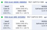
With a desktop engraving and milling machine made of aluminum CNC-2020AL, complete with a control unit with the ability to adjust spindle speed, Figure 1 and 2, the control unit contains a stepper motor driver on a TB6560AHQ chip, power supplies for the stepper motor driver and a spindle power supply.

picture 1

Figure 2
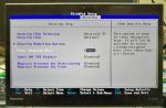
1. One of the first control controllers for CNC milling machines on the TB6560 chip was nicknamed “blue board”, Figure 3. This version of the board was discussed a lot on the forums, it has a number of disadvantages. The first is the slow PC817 optocouplers, which requires, when setting up the MACH3 machine control program, to enter the maximum allowable value in the Step pulse and Dir pulse = 15 fields. The second is poor matching of the optocoupler outputs with the inputs of the TB6560 driver, which can be solved by modifying the circuit, Figure 8 and 9. The third. - linear stabilizers for the board's power supply and, as a result, high overheating; switching stabilizers are used on subsequent boards. The fourth is the lack of galvanic isolation of the power supply circuit. The spindle relay is 5A, which in most cases is not enough and requires the use of a more powerful intermediate relay. The advantages include the presence of a connector for connecting a control panel. This controller is not used.

Figure 3.
2. The CNC machine control controller entered the market after the “blue board”, nicknamed the red board, Figure 4.
Higher frequency (fast) optocouplers 6N137 are used here. Spindle relay 10A. Availability of galvanic isolation for power supply. There is a connector for connecting the fourth axis driver. Convenient connector for connecting limit switches.

Figure 4.
3. The stepper motor controller marked TB6560-v2 is also red, but simplified, there is no power decoupling, Figure 5. Small size, but as a result of this, the size of the radiator is smaller.

Figure 5
4. Controller in an aluminum case, Figure 6. The case protects the controller from dust and metal parts; it also serves as a good heat sink. Galvanic isolation for power supply. There is a connector for powering additional +5V circuits. Fast optocouplers 6N137. N low-impedance and Low ESR capacitors. There is no relay for controlling the spindle turning on, but there are two outputs for connecting a relay (transistor switches with OK) or PWM for controlling the spindle rotation speed. Description of connecting relay control signals on the page

Figure 6
5. 4-axis controller of CNC milling and engraving machine, USB interface, Figure 7.

Figure 7
This controller does not work with the MACH3 program; it comes with its own machine control program.
6. CNC controller of the machine on the SD driver from Allegro A3977, Figure 8.

Figure 8
7.Single-channel stepper motor driver for CNC machine DQ542MA. This driver can be used when self-production a machine with a large working field and stepper motors with a current of up to 4.2A, can also work with Nema34 86mm motors, Figure 9.

Figure 9
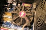
Photo of the modification of the blue stepper motor controller board on the TB6560, Figure 10.

Figure 10.
Scheme for fixing the blue stepper motor controller board on the TB6560, Figure 11.

1. Appearance boards
1 - SLOT for SD card;
2 - start button;
3 - manual control joystick;
4 - LED (for X and Y axes);
5 LED (for Z axis);
6 - leads for the spindle power button;
8 - low level pins (-GND);
9 - high level pins (+5v);
10 - pins on 3 axes (Xstep, Xdir, Ystep, Ydir, Zstep, Zdir), 2 pins each;
11 - LPT connector pins (25 pins);
12 - LPT connector (female);
13 - USB connector (only for +5v power supply);
14 and 16 - spindle frequency control (PWM 5 V);
15 - GND (for spindle);
17 - output for spindle ON and OFF;
18 - spindle speed control (analog from 0 to 10 V).

When connecting to a ready-made board with drivers for a 3-axis CNC that has an LPT output:
Install jumpers between 10 pins and 11 pins.
8 and 9 pins with 11, they are needed if additional on and off pins are allocated for the drivers (there is no specific standard, so these can be any combinations, you can find them in the description, or at random :) -)
When connecting to separate drivers with motors:
Install jumpers between the 10 Step, Dir pins of the "RFF" board and the Step, Dir pins of your drivers. (don’t forget to supply power to the drivers and motors)
Connect "RFF" to the network. Two LEDs will light up.
Insert the formatted SD card into LOT 1. Press RESET. Wait until the right LED lights up. (Approximately 5 seconds) Remove the SD card.
It will appear on it text file with the name "RFF".
Open this file and enter the following variables (Here in this form and sequence):
Example:
V=5 D=8 L=4.0 S=0 Dir X=0 Dir Y=1 Dir Z=1 F=600 H=1000 UP=0
V - conditional value from 0 to 10 of the initial speed during acceleration (acceleration).
Explanations of commands
D - step crushing installed on the motor drivers (should be the same on all three).
L is the length of passage of the carriage (portal), with one revolution of the stepper motor in mm (it should be the same on all three). Insert the rod from the handle instead of the cutter and manually rotate the motor one full turn, this line will be the L value.
S - which signal turns on the spindle, if 0 means - GND if 1 means +5v (can be selected experimentally).
Dir X, Dir Y, Dir Z, the direction of movement along the axes, can also be selected experimentally by setting 0 or 1 (it will become clear in manual mode).
F - speed at idle (G0), if F=600, then the speed is 600mm/sec.
H- maximum frequency your spindle (needed to control the spindle frequency using PWM, for example, if H = 1000, and S1000 is written in the G-code, then the output with this value will be 5v, if S500 then 2.5 v, etc., variable S in G- the code should not contain more than the variable H on SD.
The frequency at this pin is about 500 Hz.
UP - logic for controlling SD drivers (there is no standard, it can be like high level+5V, and low -) set 0 or 1. (works for me in any case. -)))
The controller itself
See video: control board with 3-axis CNC
2. Preparation of the control program (G_CODE)
The board was developed for ArtCam, so the Control program must have an extension. TAP (remember to put it in mm, not inches).
The G-code file saved on the SD card must be named G_CODE.
If you have a different extension, for example CNC, then open your file using notepad and save it as G_CODE.TAP.
x, y, z in G-code must be capitalized, the dot must be a dot, not a comma, and even an integer must have 3 zeros after the dot.
Here it is in this form:
X5.000Y34.400Z0.020
3. Manual control
Manual control is carried out using a joystick, if you have not entered the variables in the settings specified in point 1, “RFF” board
will not work even in manual mode!!!
To go to manual mode you need to press the joystick. Now try to control it. Looking at the board from above (SLOT 1 at the bottom,
12 LPT connector at the top).
Forward Y+, backward Y-, right X+, left X-, (in case of incorrect movement in Dir settings X, Dir Y, reverse the value).
Press the joystick again. The 4th LED will light up, which means you have switched to Z-axis control. Joystick up - spindle
should go up Z+, joystick down - go down Z- (if the move is incorrect, change the value in the Dir Z settings
to the opposite).
Lower the spindle until the cutter touches the workpiece. Click on button 2 start, now this is the zero point from here the execution of the G-code will begin.
4. Autonomous operation (performing G-code cutting)
Press button 2 again, briefly holding it down.
After releasing the button, the "RFF" board will begin to control your CNC machine.
5. Pause mode
Briefly press button 2 while the machine is running, cutting will stop and the spindle will rise 5mm above the workpiece. Now you can control the Z axis both up and down, and not be afraid to even go deeper into the workpiece, since after pressing button 2 again, cutting will continue from the paused value along Z. In the pause state, you can turn the spindle off and on with button 6. The X and Y axes are in Pause mode cannot be controlled.
6. Emergency stop of work with the spindle going to zero
Long-pressing button 2 while battery life, the spindle will rise 5 mm above the workpiece, do not release the button, 2 LEDs will begin to blink alternately, the 4th and 5th, when the blinking stops, release the button and the spindle will move to the zero point. Pressing button 2 again will execute the job from the beginning of the G-code.
Supports commands such as G0, G1, F, S, M3, M6 to control the spindle speed there are separate pins: PWM from 0 to 5 V and a second analog from 0 to 10 V.
Accepted command format:
X4.000Y50.005Z-0.100 M3 M6 F1000.0 S5000
There is no need to number the lines, no need to put spaces, indicate F and S only when changing.
A small example:
T1M6 G0Z5.000 G0X0.000Y0.000S50000M3 G0X17.608Y58.073Z5.000 G1Z-0.600F1000.0 G1X17.606Y58.132F1500.0 X17.599Y58.363 X17.597Y58.47 6 X17.603Y58.707 X17.605Y58.748
Demonstration of the RFF controller operation