In 2007, Philips patented an incredibly simple, but, without exaggeration, amazing TV backlight technology. With such adaptive backlighting, the eyes become less tired when viewing in the dark, the presence effect increases, the display area expands, etc. Ambilight is applicable not only to video and photo content, but also to games. Ambilight has become a hallmark of Philips TVs. Since then, Philips has been closely vigilant so that none of the major manufacturers would even think of encroaching on the sacred by creating something similar. It is probably possible to license this technology, but the conditions are somehow prohibitive, and other market players are not particularly eager to do this. Small companies also tried (and there are now companies that are doing this) to introduce similar technology in the form of separate kits, but punishment from Philips was inevitable. So, in the best case, if the company does not somehow renew the patent or its derivative, other manufacturers will only be able to produce something similar in 2027.
But such punishment does not apply to us, ordinary consumers. We are free to do what we see fit. Today I will tell you in detail how to make your own adaptive backlight for a TV or monitor like Philips Ambilight (hereinafter simply Ambilight). For some, the article will not contain anything new, because... There are dozens of such projects, and hundreds of articles have been written in different languages, and there are thousands of people who have already done this for themselves. But for many this can all be very interesting. You don't need any special skills. Only basic knowledge of physics for the 8th grade of high school. Well, just a little bit of soldering of wires.
So that you can better understand what I’m talking about, I’ll give you my example of what happened. The real costs for a 42" TV are about 1000 rubles and 2 hours of work.
The video does not convey all the sensations and effect in its entirety, but the children sat with their mouths open for the first time.
Possible implementation options
There are several options for implementing Ambilight. They depend on the video source.The cheapest, simplest and most effective option is a PC running Windows, Mac OS X or Linux as the signal source. Windows boxes on Atom processors, which cost from $70, are now very common. All of them are ideal for implementing Ambilight. I’ve been using various Windows boxes (in a TV stand) as a media player for several years now, I’ve written a small handful of reviews and consider them the best TV set-top boxes for media content. The hardware implementation of this option is the same for all of the listed operating systems. It is this option that I will talk about in the article.. The software part will be related to the Windows system; AmbiBox will act as a universal control program. Can be used with Mac OS X and Linux.
The second option is that the signal source is a media set-top box based on Android, of which there are also a huge number. This option is the most problematic. First, the highlighting will only work in the Kodi media harvester (and its offshoots). Secondly, in the vast majority of cases, everything works only with hardware video decoding disabled, which is unacceptable for most boxes. The hardware implementation of the project also imposes certain requirements. I won’t touch on it, but if there’s something specific you’re interested in, I’ll try to answer in the comments.
The third option is a solution independent of the signal source. This is the most expensive, but absolutely universal solution, because... the signal is taken directly from the HDMI cable. For it you will need a fairly powerful microcomputer (such as a Raspberry Pi), an HDMI splitter, an HDMI-RCA AV converter, a USB 2.0 analog video capture device. Only with this option you can be guaranteed to use Ambilight with any TV set-top box/receiver, Android boxes, Apple TV, game consoles (for example, Xbox One, PlayStation 4) and other devices that have an HDMI output. For the version with 1080p60 support, the cost of components (without LED strip) will be about $70, with 2160p60 support - about $100. This option is very interesting, but a separate article needs to be written on it.
Hardware
To implement it, you will need three main components: a controllable RGB LED strip, a power supply, and an Arduino microcomputer.First a little explanation.
WS2811 is a three-channel controller/driver (chip) for RGB LEDs with single-wire control (addressing an arbitrary LED). WS2812B is an RGB LED in an SMD 5050 package, which already has a WS2811 controller built into it.
For simplicity, the LED strips suitable for the project are called WS2811 or WS2812B.
WS2812B strip is a strip on which WS2812B LEDs are placed in series. The strip operates with a voltage of 5 V. There are strips with different densities of LEDs. Usually it is: 144, 90, 74, 60, 30 per meter. There are different degrees of protection. Most often these are: IP20-30 (protection against solid particles), IP65 (protection against dust and water jets), IP67 (protection against dust and protection against partial or short-term immersion in water to a depth of 1 m). Backing in black and white.
Here is an example of such a tape:

WS2811 tape is a tape on which a WS2811 controller and some kind of RGB LED are placed in series. There are options designed for voltages of 5 V and 12 V. Density and protection are similar to the previous option.
Here is an example of such a tape:

There are also WS2811 “strips” with large and powerful LEDs, as in the photo below. They are also suitable for implementing Ambilight for some huge panel.

Which tape to choose, WS2812B and WS2811?
An important factor is the power supply of the tape, which I will talk about a little later.
If you have a power supply at home that is suitable for power (often power supplies are left at home from old or damaged equipment), then choose a tape based on the voltage of the power supply, i.e. 5 V - WS2812B, 12 V - WS2811. In this case, you will simply save money.
From myself I can give a recommendation. If the total number of LEDs in the system is no more than 120, then WS2812B. If more than 120, then WS2811 with an operating voltage of 12 V. You will understand why this is so when it comes to connecting the tape to the power supply.
What level of tape protection should I choose?
For most, IP65 is suitable, because... On one side it is coated with “silicone” (epoxy resin), and on the other there is a 3M self-adhesive surface. This tape is convenient to mount on a TV or monitor and is convenient to wipe off dust.
What LED density should I choose?
For the project, strips with a density of 30 to 60 LEDs per meter are suitable (of course, 144 is possible, no one prohibits). The higher the density, the greater the Ambilight resolution (number of zones) and the greater the maximum overall brightness. But it’s worth considering that the more LEDs in the project, the more complex the strip’s power supply circuit will be, and a more powerful power supply will be needed. The maximum number of LEDs in a project is 300.
Buying tape
If your TV or monitor is hanging on the wall, and all 4 sides have a lot of free space nearby, then the tape is best placed at the back along the perimeter on all 4 sides for maximum effect. If your TV or monitor is installed on a stand, or there is little free space at the bottom, then the tape should be placed on the back on 3 sides (i.e. the bottom without tape).
For myself, I chose a white WS2812B IP65 strip with 30 LEDs per meter. I already had a suitable 5V power supply. I was deciding whether to use 60 or 30 LEDs per meter, but chose the latter after reviewing the video with ready-made examples of implementation - the brightness and resolution suited me, and the power supply was easier to organize and there were fewer wires. Aliexpress has a huge number of lots of WS2812B tapes. I ordered 5 meters for $16. For my TV (42", 3 sides) I only needed 2 meters, i.e. I could buy it for $10, the remaining three meters for a friend. Prices often change among sellers, there are many offers, so just choose a cheap lot on Aliexpress with a high rating (search keywords - WS2812B IP65 go WS2811 12V IP65).


Buying a power supply for the tape
The power supply is selected according to power and voltage. For WS2812B - voltage 5 V. For WS2811 - 5 or 12 V. The maximum power consumption of one WS2812B LED is 0.3 W. For WS2811 in most cases it is the same. Those. The power supply power must be at least N * 0.3 W, where N is the number of LEDs in the project.
For example, you have a 42" TV, you chose a WS2812B strip with 30 LEDs per meter, you need 3 meters of strip on all 4 sides. You will need a power supply with a voltage of 5 V and a maximum power of 0.3 * 30 * 3 = 27 W , i.e. 5 V / 6 A. My implementation uses only 3 sides, a total of 60 LEDs (57 to be precise) - power from 18 W, i.e. 5 V / 4 A.
I’ve had the ORICO CSA-5U (8 A) multiport USB charger lying idle for a long time, left over from an old review. Its ports are powered in parallel (this is critically important), this charger is ideal for me as a power supply, because... I will connect the tape through 2 parallel connections (explanations will be later in the article).

If I didn’t have this charger, I would have chosen it (there is information that this particular power supply is equipped with 2.5 A internals, so you need to study this issue in more detail with the seller, or look at other models).

Buying a microcomputer
Ambilight will be controlled by an Arduino microcomputer. Arduino Nano on Aliexpress costs about apiece.

Costs for my option (for 42" TV):
$10 - 2 meters WS2812B IP65 (30 LEDs per meter)
$4 - 5 V / 4 A power supply (I didn’t spend any money on a power supply, I’m giving the cost for clarity)
$2.5 - Arduino Nano
-----------
16,5$
or 1000 rubles
Hardware implementation
The most important thing is to properly organize the power supply for the tape. The tape is long, the voltage sags at high currents, especially at 5 V. Most of the problems that arise for those who make their own Ambilight are related to power supply. I use the rule - you need to make a separate power supply for every 10 W of maximum power consumption at 5 V and 25 W of power consumption at 12 V. The length of the power supply (from the power supply to the tape itself) should be minimal (without reserve), especially at 5 IN.
The general connection diagram is as follows (the diagram shows the power connection for my version):

Power is supplied to the tape at both ends - two parallel connections. For example, if I were lighting on all 4 sides, and the strip had 60 LEDs per meter (i.e. maximum power 54 W), then I would make the following power supply:

The connecting wires must be used appropriately; the smaller the gauge (AWG), the better, so that they are sufficient for the calculated current strength.
Two contacts go to the Arduino from the tape. GND, which needs to be connected to the corresponding pin on the Arduino. And DATA, which needs to be connected to the sixth digital pin through a 300-550 Ohm resistor (preferably 470 Ohms). If you don’t have a resistor, then in most cases everything will work fine without it, but it’s better to have one. You can buy a resistor for a couple of kopecks at any radio store. The Arduino microcomputer itself can be placed in any convenient case; many people use a Kinder surprise egg for this. The Arduino should be placed as close to the tape as possible so that the DATA connection has a minimum length.
Soldering wires to the tape is simple. The main rule is that the contact time with the soldering iron should be minimal; you cannot “mess around” with the soldering iron.
In my case it turned out like this:


Two black high-quality USB cables were used for power, and a white one for connecting to the computer. I ran out of white heat shrink tubing so I used red ones. Not as “pretty”, but it suits me (it’s hidden behind the TV anyway).
An important question is how to bend the tape at a right angle? If you have a strip of 60 LEDs, then the strip needs to be cut and connected with short wires (placing it all in a heat-shrinkable tube). You can buy special three-pin corner connectors for LED strips (there are 4 pins in the picture, just for example):

If you have a strip of 30 LEDs, then the distance between the LEDs is large, you can easily make a corner without cutting. Remove a piece of the “silicone” coating, insulate (you can even use tape) the contact pad and bend it according to the diagram:
I cut a piece of tape to practice. The main thing is not to overdo it - bend it slightly once and that’s it. There is no need to bend it here and there, there is no need to press the bend line too hard.

Here is a view from the back of the TV, all the wires go through the hole into the cabinet:

Software part
This is the simplest thing.We connect the Arduino microcomputer via USB. The driver (CH340 serial interface) will be installed automatically. If this does not happen, then in the Arduino IDE folder there is a Drivers folder with everything you need.
Launch the Arduino IDE and open the Adalight.ino file.

We change the number of LEDs in the code. I'm 57.

Tools > Board > Arduino nano
Tools > Port > Select the COM port (the desired option will be there)
Click the “Download” button:

The program will inform you when the download is complete (this is literally a couple of seconds).
Ready. You need to disconnect the Arduino from USB and connect it again. The tape will light up sequentially in red, green and blue - the Arduino has been activated and is ready for use.
Download and install the program. In the program, click “More settings” and specify the device - Adalight, COM port and the number of LEDs. Select the number of frames to capture (up to 60).

Next, click “Show Capture Zones” > “Zone Setup Wizard”. Select your ribbon configuration.

Click Apply and Save Settings. This completes the basic settings. Then you can experiment with the size of the capture zones, color correct the tape, etc. The program has many different settings.

To activate a profile, just double-click on the corresponding icon (AmbiBox profiles) in the Windows notification area. The tape will light up immediately. It can also be turned off by double clicking.
That's basically it. You saw the result at the beginning of the article. Nothing complicated, cheap and healthy. I'm sure you can do better, so share your crafts in the comments.
TVs with dynamic backlighting around the display frame are one of Philips' signature features. And unlike many others, it works. However, everything comes at a price, and TVs with Ambilight and increased immersion are more expensive than many other models.
Russian developers have proposed a method that will allow monitors from any manufacturer to be equipped with dynamic backlighting. To do this, you don’t even have to take the device to a service center: it just takes a little time and perseverance.
In general, such lighting can be purchased in the form of radio components and configured independently. But, as practice shows, this is almost comparable to ready-made options from PaintPack.
There are two main models available: a monitor version (30 LEDs) and a TV version (60 LEDs). There is also a very simple one - for 10 LEDs, but it is suitable only for the smallest monitors.
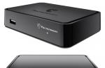
The TV version is equipped with an external power supply. Also in its favor is a larger number of LEDs, which gives a larger illumination area (it will glow wider and higher, in other words). If such options are not suitable for any reason, you can contact the developers: for a small additional payment they will offer a modified version.
mindrunway.ruPaintPack, in fact, is a small case to which removable LED strips are connected on both sides. The box with the filling contains indicators and a power connector, as well as microUSB for connecting to a PC. There is also a master connector (proprietary) for connecting two devices in series.
The device body is placed on the back of the TV or monitor. Then the LED strips are laid in accordance with the instructions, the power is connected and the magic begins. When connecting PaintPack to a computer via a USB connector, you must install drivers and configure the device in the bundled program.
 mysku.ru
 Configuration is done using the AmbiBox package. You need to go to the “Intelligent Backlight” menu, select the screen capture method and one of the operating modes offered in the program:
- Static background - any color can be set, the LED glow can be adjusted.
- Color music - the backlight will blink in time with the sound of the music. The backlight color is set to green-yellow.
- Dynamic background - a smooth flow of one color into another.
- Screen capture is the main mode of operation.
This mode allows you to capture color from the movies and games you watch. The backlight color will change according to the image on the screen, dividing into upper, lower and side zones (each separately).
PaintPack works a little slower than the official Philips analogue. But taking into account the difference in cost and the possibility of upgrading any device, the choice is obvious.
What is Hyperion Ambilight
A backlight technology for televisions that was invented and patented by Philips Electronics.
It is a backlight that, analyzing the color image of the frame on the TV screen, reproduces diffused light around the perimeter of the TV. Thanks to this, the surface of the wall behind the TV body is dynamically illuminated, thereby adding a halo to the intensity of the image on the screen itself and visually increasing the size of the image.
1. Basic iron
Since the technology is patented, we will not see it on TVs other than the Philips brand for many years. By the way, I owned such a TV, with three-sided backlighting, but it was so slow that I sold it 6 days after purchase. Well, we'll have to do it ourselves... For this we will need:
- Raspberry Pi 3 link ($42)- just take the latest version of Raspberry, if you plan to use it as a media server, then I advise you to take something more powerful, for example Asus Tinker Board . If you have a Raspberry Pi 2 lying around, then everything will work well on it, without any delays.
- LED strip APA102 link ($8/meter)- there are only two options, either take the original APA102, or its analogue SK9822, which is cheaper, but works exactly the same. I'm using analog. I advise you to take Black IP67 30/meter. IP67 comes with silicone protection, which does not turn yellow over time and protects against dust and interference. Regarding the number of diodes, 30 per meter is quite enough, and the power supply can be found in a “laptop” version. Take the TV on all 4 sides, even if it is on a stand. A 48-inch TV requires exactly 3 meters of tape. I recommend taking all the necessary tape at once from one seller and in one order, since different batches of tape may have different shades, this will hurt the eye. Never believe that a system can be built on ws28*, just look at the characteristics:
I had an extremely sad experience with the ws2801 tape: firstly, it is frankly slow, it does not have enough refresh rate, secondly, the white is not white, you need to adjust it, thirdly, the diodes constantly blink randomly, fourthly, they simply fall off Fifthly, chips from this tape must be soldered.
- Power supply 5V 8A link ($11)- the choice of block depends on the configuration of the tape, I’ll just give my calculation example: a tape of 30 diodes/meter consumes 9W per 1 meter (in cases when white is on, in reality it is much less), we count to the maximum: 9W * 3 (number of meters) + 20% reserve = 32.4 W, the power supply produces 5 * 8 = 40 W is quite suitable, and all other devices can be powered from it.
- Connectors- P Let's not say, why complicate things, let's take and order some connectors:
2. Iron assembly
We assemble according to the following scheme. It is important to energize the beginning and end of the tape so that the glow is uniform. Be sure to connect the power supply of the tape to the common ground. To avoid possible signal interference, you can use ferrite filters, but I did it without them and no problems were found.
We try it on, cut it, connect it with corners, glue it.
The LED strip comes with a standard adhesive base - the strip does not stick to it and will fall off quickly. I bought foam adhesive tape for attaching mirrors at a construction hypermarket. Be sure to degrease the surface of the TV. The TV body can be rounded; it becomes possible to stick the tape at an angle so that the diodes shine more on the sides, but I do not recommend doing this. It is worth sticking the tape strictly perpendicular to the wall. The ideal distance from the wall is 15cm-20cm. In my case, it turned out to be 24cm, due to the shape of the TV stand.
The raspberry can also be glued to the back of the TV. I glued it with Velcro from clothes so that I could remove it.
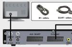
I read that this scart adapter does not work on all TVs, but I advise you to try it, it’s cheap. The adapter must be set to OUT mode.

In 2007, Philips patented an incredibly simple, but, without exaggeration, amazing TV backlight technology. With such adaptive backlighting, the eyes become less tired when viewing in the dark, the presence effect increases, the display area expands, etc. Ambilight is applicable not only to video and photo content, but also to games. Ambilight has become a hallmark of Philips TVs. Since then, Philips has been closely vigilant so that none of the major manufacturers would even think of encroaching on the sacred by creating something similar. It is probably possible to license this technology, but the conditions are somehow prohibitive, and other market players are not particularly eager to do this. Small companies also tried (and there are now companies that are doing this) to introduce similar technology in the form of separate kits, but punishment from Philips was inevitable. So, in the best case, if the company does not somehow renew the patent or its derivative, other manufacturers will only be able to produce something similar in 2027.
But such punishment does not apply to us, ordinary consumers. We are free to do what we see fit. Today I will tell you in detail how to make your own adaptive backlight for a TV or monitor like Philips Ambilight (hereinafter simply Ambilight). For some, the article will not contain anything new, because... There are dozens of such projects, and hundreds of articles have been written in different languages, and there are thousands of people who have already done this for themselves. But for many this can all be very interesting. You don't need any special skills. Only basic knowledge of physics for the 8th grade of high school. Well, just a little bit of soldering of wires.
So that you can better understand what I’m talking about, I’ll give you my example of what happened. The real costs for a 42" TV are about 1000 rubles and 2 hours of work.
The video does not convey all the sensations and effect in its entirety, but the children sat with their mouths open for the first time.
Possible implementation options
There are several options for implementing Ambilight. They depend on the video source.The cheapest, simplest and most effective option is a PC running Windows, Mac OS X or Linux as the signal source. Windows boxes on Atom processors, which cost from $70, are now very common. All of them are ideal for implementing Ambilight. I’ve been using various Windows boxes (in a TV stand) as a media player for several years now, I’ve written a small handful of reviews and consider them the best TV set-top boxes for media content. The hardware implementation of this option is the same for all of the listed operating systems. It is this option that I will talk about in the article.. The software part will be related to the Windows system; AmbiBox will act as a universal control program. Can be used with Mac OS X and Linux.
The second option is that the signal source is a media set-top box based on Android, of which there are also a huge number. This option is the most problematic. First, the highlighting will only work in the Kodi media harvester (and its offshoots). Secondly, in the vast majority of cases, everything works only with hardware video decoding disabled, which is unacceptable for most boxes. The hardware implementation of the project also imposes certain requirements. I won’t touch on it, but if there’s something specific you’re interested in, I’ll try to answer in the comments.
The third option is a solution independent of the signal source. This is the most expensive, but absolutely universal solution, because... the signal is taken directly from the HDMI cable. For it you will need a fairly powerful microcomputer (such as a Raspberry Pi), an HDMI splitter, an HDMI-RCA AV converter, a USB 2.0 analog video capture device. Only with this option you can be guaranteed to use Ambilight with any TV set-top box/receiver, Android boxes, Apple TV, game consoles (for example, Xbox One, PlayStation 4) and other devices that have an HDMI output. For the version with 1080p60 support, the cost of components (without LED strip) will be about $70, with 2160p60 support - about $100. This option is very interesting, but a separate article needs to be written on it.
Hardware
To implement it, you will need three main components: a controllable RGB LED strip, a power supply, and an Arduino microcomputer.First a little explanation.
WS2811 is a three-channel controller/driver (chip) for RGB LEDs with single-wire control (addressing an arbitrary LED). WS2812B is an RGB LED in an SMD 5050 package, which already has a WS2811 controller built into it.
For simplicity, the LED strips suitable for the project are called WS2811 or WS2812B.
WS2812B strip is a strip on which WS2812B LEDs are placed in series. The strip operates with a voltage of 5 V. There are strips with different densities of LEDs. Usually it is: 144, 90, 74, 60, 30 per meter. There are different degrees of protection. Most often these are: IP20-30 (protection against solid particles), IP65 (protection against dust and water jets), IP67 (protection against dust and protection against partial or short-term immersion in water to a depth of 1 m). Backing in black and white.
Here is an example of such a tape:
WS2811 tape is a tape on which a WS2811 controller and some kind of RGB LED are placed in series. There are options designed for voltages of 5 V and 12 V. Density and protection are similar to the previous option.
Here is an example of such a tape:
There are also WS2811 “strips” with large and powerful LEDs, as in the photo below. They are also suitable for implementing Ambilight for some huge panel.
Which tape to choose, WS2812B and WS2811?
An important factor is the power supply of the tape, which I will talk about a little later.
If you have a power supply at home that is suitable for power (often power supplies are left at home from old or damaged equipment), then choose a tape based on the voltage of the power supply, i.e. 5 V - WS2812B, 12 V - WS2811. In this case, you will simply save money.
From myself I can give a recommendation. If the total number of LEDs in the system is no more than 120, then WS2812B. If more than 120, then WS2811 with an operating voltage of 12 V. You will understand why this is so when it comes to connecting the tape to the power supply.
What level of tape protection should I choose?
For most, IP65 is suitable, because... On one side it is coated with “silicone” (epoxy resin), and on the other there is a 3M self-adhesive surface. This tape is convenient to mount on a TV or monitor and is convenient to wipe off dust.
What LED density should I choose?
For the project, strips with a density of 30 to 60 LEDs per meter are suitable (of course, 144 is possible, no one prohibits). The higher the density, the greater the Ambilight resolution (number of zones) and the greater the maximum overall brightness. But it’s worth considering that the more LEDs in the project, the more complex the strip’s power supply circuit will be, and a more powerful power supply will be needed. The maximum number of LEDs in a project is 300.
Buying tape
If your TV or monitor is hanging on the wall, and all 4 sides have a lot of free space nearby, then the tape is best placed at the back along the perimeter on all 4 sides for maximum effect. If your TV or monitor is installed on a stand, or there is little free space at the bottom, then the tape should be placed on the back on 3 sides (i.e. the bottom without tape).
For myself, I chose a white WS2812B IP65 strip with 30 LEDs per meter. I already had a suitable 5V power supply. I was deciding whether to use 60 or 30 LEDs per meter, but chose the latter after reviewing the video with ready-made examples of implementation - the brightness and resolution suited me, and the power supply was easier to organize and there were fewer wires. Aliexpress has a huge number of lots of WS2812B tapes. I ordered 5 meters for $16. For my TV (42", 3 sides) I only needed 2 meters, i.e. I could buy it for $10, the remaining three meters for a friend. Prices often change among sellers, there are many offers, so just choose a cheap lot on Aliexpress with a high rating (search keywords - WS2812B IP65 go WS2811 12V IP65).
Buying a power supply for the tape
The power supply is selected according to power and voltage. For WS2812B - voltage 5 V. For WS2811 - 5 or 12 V. The maximum power consumption of one WS2812B LED is 0.3 W. For WS2811 in most cases it is the same. Those. The power supply power must be at least N * 0.3 W, where N is the number of LEDs in the project.
For example, you have a 42" TV, you chose a WS2812B strip with 30 LEDs per meter, you need 3 meters of strip on all 4 sides. You will need a power supply with a voltage of 5 V and a maximum power of 0.3 * 30 * 3 = 27 W , i.e. 5 V / 6 A. My implementation uses only 3 sides, a total of 60 LEDs (57 to be precise) - power from 18 W, i.e. 5 V / 4 A.
I’ve had the ORICO CSA-5U (8 A) multiport USB charger lying idle for a long time, left over from an old review. Its ports are powered in parallel (this is critically important), this charger is ideal for me as a power supply, because... I will connect the tape through 2 parallel connections (explanations will be later in the article).
If I didn’t have this charger, I would have chosen it (there is information that this particular power supply is equipped with 2.5 A internals, so you need to study this issue in more detail with the seller, or look at other models).
Buying a microcomputer
Ambilight will be controlled by an Arduino microcomputer. Arduino Nano on Aliexpress costs about apiece.
Costs for my option (for 42" TV):
$10 - 2 meters WS2812B IP65 (30 LEDs per meter)
$4 - 5 V / 4 A power supply (I didn’t spend any money on a power supply, I’m giving the cost for clarity)
$2.5 - Arduino Nano
-----------
16,5$
or 1000 rubles
Hardware implementation
The most important thing is to properly organize the power supply for the tape. The tape is long, the voltage sags at high currents, especially at 5 V. Most of the problems that arise for those who make their own Ambilight are related to power supply. I use the rule - you need to make a separate power supply for every 10 W of maximum power consumption at 5 V and 25 W of power consumption at 12 V. The length of the power supply (from the power supply to the tape itself) should be minimal (without reserve), especially at 5 IN.
The general connection diagram is as follows (the diagram shows the power connection for my version):
Power is supplied to the tape at both ends - two parallel connections. For example, if I were lighting on all 4 sides, and the strip had 60 LEDs per meter (i.e. maximum power 54 W), then I would make the following power supply:
The connecting wires must be used appropriately; the smaller the gauge (AWG), the better, so that they are sufficient for the calculated current strength.
Two contacts go to the Arduino from the tape. GND, which needs to be connected to the corresponding pin on the Arduino. And DATA, which needs to be connected to the sixth digital pin through a 300-550 Ohm resistor (preferably 470 Ohms). If you don’t have a resistor, then in most cases everything will work fine without it, but it’s better to have one. You can buy a resistor for a couple of kopecks at any radio store. The Arduino microcomputer itself can be placed in any convenient case; many people use a Kinder surprise egg for this. The Arduino should be placed as close to the tape as possible so that the DATA connection has a minimum length.
Soldering wires to the tape is simple. The main rule is that the contact time with the soldering iron should be minimal; you cannot “mess around” with the soldering iron.
In my case it turned out like this:
Two black high-quality USB cables were used for power, and a white one for connecting to the computer. I ran out of white heat shrink tubing so I used red ones. Not as “pretty”, but it suits me (it’s hidden behind the TV anyway).
An important question is how to bend the tape at a right angle? If you have a strip of 60 LEDs, then the strip needs to be cut and connected with short wires (placing it all in a heat-shrinkable tube). You can buy special three-pin corner connectors for LED strips (there are 4 pins in the picture, just for example):
If you have a strip of 30 LEDs, then the distance between the LEDs is large, you can easily make a corner without cutting. Remove a piece of the “silicone” coating, insulate (you can even use tape) the contact pad and bend it according to the diagram:
I cut a piece of tape to practice. The main thing is not to overdo it - bend it slightly once and that’s it. There is no need to bend it here and there, there is no need to press the bend line too hard.
Here is a view from the back of the TV, all the wires go through the hole into the cabinet:
Software part
This is the simplest thing.We connect the Arduino microcomputer via USB. The driver (CH340 serial interface) will be installed automatically. If this does not happen, then in the Arduino IDE folder there is a Drivers folder with everything you need.
Launch the Arduino IDE and open the Adalight.ino file.
We change the number of LEDs in the code. I'm 57.
Tools > Board > Arduino nano
Tools > Port > Select the COM port (the desired option will be there)
Click the “Download” button:
The program will inform you when the download is complete (this is literally a couple of seconds).
Ready. You need to disconnect the Arduino from USB and connect it again. The tape will light up sequentially in red, green and blue - the Arduino has been activated and is ready for use.
Download and install the program. In the program, click “More settings” and specify the device - Adalight, COM port and the number of LEDs. Select the number of frames to capture (up to 60).
Next, click “Show Capture Zones” > “Zone Setup Wizard”. Select your ribbon configuration.
Click Apply and Save Settings. This completes the basic settings. Then you can experiment with the size of the capture zones, color correct the tape, etc. The program has many different settings.
To activate a profile, just double-click on the corresponding icon (AmbiBox profiles) in the Windows notification area. The tape will light up immediately. It can also be turned off by double clicking.
That's basically it. You saw the result at the beginning of the article. Nothing complicated, cheap and healthy. I'm sure you can do better, so share your crafts in the comments.
Introduction
If you like to watch movies on your computer in the dark or play games, you can expand the capabilities of your monitor. Dynamic backlight visually expands the boundaries of the screen and thanks to it your eyes will be less tired. This project is very simple and since I am new to working with Arduino, I can recommend starting to create something for the home with this project.
So, we will need:
- Any Arduino (UNO, Nano, it doesn’t matter).
- From 1 to 2 meters of WS2812B LED strip, which you can read about, can be ordered on Aliexpress. I advise you to take 60 LEDs per meter for a better effect, but 30 will do.
- Double-sided tape or some kind of glue.
- Power source 5V 2A (charger from a tablet, for example).
- 220 Ohm resistor.
- Soldering tools.
- Necessary software for the computer, namely: Arduino IDE, AmbiBox, library for Arduino IDE - FastLed.
Let's get started.
Connection
The LED strip has three contacts - Plus (+), Ground (G, GND) and input (IN), and there are also arrows indicating the direction of the signal along the strip. Our task is to cut 4 pieces of LED strip in this way. so that the top strip is equal to the bottom, the right - to the left. We will measure by applying the tape from the back of our monitor. In general, you need to do it as in the picture below.
 It is important that the number of LEDs on top and bottom is the same, the same applies to the right and left sides. You also need to take into account the direction of the arrows on the tape itself and solder in order, as in the picture.
Now we need to connect the tape to the Arduino according to the diagram:

The minus from the power goes to pin G on the tape and the GND pin on the Arduino itself. Plus goes directly to the (+) pin on the tape, and the control wire goes through a resistor from the tape to the desired port. The main thing is to remember the port.
Actually, the connection is complete here.
Settings
Open the installed Arduino IDE and install the FastLed library (In the top menu, select “Sketch” - “Connect library” - “Add ZIP library” and select the downloaded archive with the library).
Now, using the Arduino IDE, upload the sketch to the Arduino:
#include "FastLED.h" #define NUM_LEDS 44 // Number of LEDs. #define PIN 6 // Port to which the control wire is connected. #define serialRate 115200 // Adalight sends a "Magic Word" (prefix) before sending data. uint8_t prefix = ("A", "d", "a"), hi, lo, chk, i; // Initialize the feed. CRGB leds; void setup() ( FastLED.addLeds(leds, NUM_LEDS); // LED test. LEDS.showColor(CRGB(255, 0, 0)); delay(500); LEDS.showColor(CRGB(0, 255, 0) ); delay(500); LEDS.showColor(CRGB(0, 0, 255)); delay(500); LEDS.showColor(CRGB(0, 0, 0)); Serial.begin(serialRate); Serial.print ("Ada\n"); // Send the "magic word" to connect to the program. ) void loop() ( // Wait for the first byte from the magic word. for(i = 0; i< sizeof prefix; ++i) { waitLoop: while (!Serial.available()); // Проверка следующего байта из магического слова. if(prefix[i] == Serial.read()) continue; // В противном случае начинаем все с начала. i = 0; goto waitLoop; } // Ждем старший и младший байт, а так же контрольную сумму. while (!Serial.available()); hi = Serial.read(); while (!Serial.available()); lo = Serial.read(); while (!Serial.available()); chk = Serial.read(); // Если контрольная сумма не совпала, начинаем все с начала. if (chk != (hi ^ lo ^ 0x55)) { i = 0; goto waitLoop; } memset(leds, 0, NUM_LEDS * sizeof(struct CRGB)); // Получаем данные и настраиваем соответствующий светодиод. for (uint8_t i = 0; i < NUM_LEDS; i++) { byte r, g, b; while(!Serial.available()); r = Serial.read(); while(!Serial.available()); g = Serial.read(); while(!Serial.available()); b = Serial.read(); leds[i].r = r; leds[i].g = g; leds[i].b = b; } // Отобразить новое состояние ленты. FastLED.show(); }
Before filling, you need to indicate the number of LEDs you have in total and the port to which you soldered the control wire.
I got 44 LEDs and used the 6th port.
If you have a tape and the Arduino is already connected to power, then after filling in the sketch the tape should blink in three colors; if this does not happen, then disconnect the USB cable and insert it again.
Now we need to install the AmbiBox program.
During installation, the program will ask which device will be used, we need to specify Adalight.
In it we need to go to the “Intelligent monitor backlight” tab.

Then click "More settings", all functions are now displayed.

We need to indicate the port to which the Arduino is connected (number 1 in the picture).
We need to indicate the number of LEDs we got (number 2 in the picture).
Select a screen capture method. It's up to you, experiment and choose the one that suits you. I use the Windows 8 method (number 3 in the picture).
You can also click “Show capture zones” (number 4) and configure them as the tape is pasted. Well. for example, if you have corners without LEDs, then the zones can be shifted.
Don't forget to enable autorun with Windows in the "program settings" tab.
That's all. Everything should already be working.
Video
Please enable javascript for comments to work.