First you need to decide on the terminology.
as such charge-discharge controllers do not exist. This is nonsense. There is no point in managing the discharge. The discharge current depends on the load - as much as it needs, so much it will take. The only thing to do when discharging is to monitor the voltage on the battery in order to prevent it from overdischarging. For this, apply.
At the same time, separately controllers charge not only exist, but are absolutely necessary for the process of charging li-ion batteries. It is they who set the required current, determine the moment when the charge ends, monitor the temperature, etc. The charge controller is an integral part of any.
Based on my experience, I can say that a charge / discharge controller is actually understood as a circuit for protecting the battery from too deep a discharge and, conversely, overcharging.
In other words, when talking about a charge / discharge controller, we are talking about the protection built into almost all lithium-ion batteries (PCB or PCM modules). There she is:
And here they are too: 
It is obvious that protection boards are presented in various form factors and are assembled using various electronic components. In this article, we will just look at options for protecting Li-ion batteries (or, if you like, discharge / charge controllers).
Charge-discharge controllers
Since this name is so well established in society, we will also use it. Let's start with perhaps the most common option on the DW01 (Plus) chip.
DW01-Plus
Such a protective board for li-ion batteries is found in every second cell phone battery. To get to it, just tear off the self-adhesive with the inscriptions, which is pasted over the battery.

The DW01 chip itself is six-legged, and two field-effect transistors are structurally made in one package in the form of an 8-leg assembly.
Pin 1 and 3 are the control of the overcharge (FET1) and overcharge (FET2) protection keys, respectively. Threshold voltages: 2.4 and 4.25 Volts. Conclusion 2 - a sensor that measures the voltage drop across the field-effect transistors, due to which overcurrent protection is implemented. The transient resistance of transistors acts as a measuring shunt, so the response threshold has a very large spread from product to product.
The whole scheme looks something like this: 
The right microcircuit marked 8205A is the field-effect transistors that act as keys in the circuit.
S-8241 Series
SEIKO has developed specialized circuits to protect Lithium Ion and Lithium Polymer batteries from overdischarge/overcharge. To protect one can, integrated circuits of the S-8241 series are used. 
The over-discharge and over-charge protection keys operate at 2.3V and 4.35V, respectively. Current protection is activated when the voltage drop across FET1-FET2 is 200 mV.
AAT8660 Series
LV51140T
A similar protection scheme for lithium single-cell batteries with protection against overdischarge, overcharge, excess charge and discharge currents. Implemented using the LV51140T chip. 
Threshold voltages: 2.5 and 4.25 Volts. The second leg of the microcircuit is the input of the current overload detector (limit values: 0.2V when discharging and -0.7V when charging). Pin 4 is not used.
R5421N Series
The circuit design is similar to the previous ones. In operating mode, the microcircuit consumes about 3 μA, in blocking mode - about 0.3 μA (letter C in the designation) and 1 μA (letter F in the designation). 
The R5421N series contains several modifications that differ in the magnitude of the response voltage during recharging. Details are given in the table:
SA57608
Another version of the charge / discharge controller, only on the SA57608 chip. 
The voltages at which the microcircuit disconnects the jar from external circuits depend on the letter index. See table for details:
SA57608 consumes a fairly large current in sleep mode - about 300 μA, which distinguishes it from the above analogues for the worse (there consumed currents are of the order of fractions of a microampere).
LC05111CMT
And finally, we offer an interesting solution from one of the world leaders in the production of electronic components On Semiconductor - a charge-discharge controller on a LC05111CMT chip. 
The solution is interesting in that the key MOSFETs are built into the microcircuit itself, so only a couple of resistors and one capacitor remained from the attached elements.
The transient resistance of the built-in transistors is ~11 milliohms (0.011 ohms). The maximum charge/discharge current is 10A. The maximum voltage between terminals S1 and S2 is 24 Volts (this is important when combining batteries into batteries).
The microcircuit is produced in the package WDFN6 2.6x4.0, 0.65P, Dual Flag.
The circuitry, as expected, provides protection against overcharge/discharge, overcurrent in the load, and overcharge current.
Charge controllers and protection circuits - what's the difference?
It is important to understand that the protection module and charge controllers are not the same thing. Yes, their functions overlap to some extent, but it would be a mistake to call the protection module built into the battery a charge controller. Now let me explain the difference.
The most important role of any charge controller is to implement the correct charge profile (usually CC/CV - constant current/constant voltage). That is, the charge controller must be able to limit the charging current at a given level, thereby controlling the amount of energy "poured" into the battery per unit time. Excess energy is released as heat, so any charge controller gets quite hot during operation.
For this reason, charge controllers are never built into the battery (unlike protection boards). The controllers are just part of the right charger and nothing more.
In addition, no protection board (or protection module, call it what you want) is capable of limiting the charge current. The board only controls the voltage on the bank itself and, if it goes beyond the predetermined limits, opens the output keys, thereby disconnecting the bank from the outside world. By the way, short circuit protection also works on the same principle - in the event of a short circuit, the voltage on the bank drops sharply and the deep discharge protection circuit is triggered.
The confusion between the protection circuits of lithium batteries and charge controllers arose due to the similarity of the response threshold (~ 4.2V). Only in the case of the protection module, the can is completely disconnected from the external terminals, and in the case of the charge controller, it switches to the voltage stabilization mode and a gradual decrease in the charging current.

The invention and use of tools with autonomous power sources has become one of the hallmarks of our time. More and more active components are being developed and introduced to improve the performance of battery assemblies. Unfortunately, batteries cannot work without recharging. And if on devices that have constant access to the mains, the issue is solved by built-in sources, then for powerful power sources, for example, a screwdriver, separate chargers for lithium batteries are needed, taking into account the characteristics of different types of batteries.
In recent years, products based on a lithium-ion active component have been increasingly used. And this is quite understandable, since these power sources have proven themselves from a very good side:
- they have no memory effect;
- almost completely eliminated self-discharge;
- can work at sub-zero temperatures;
- hold the discharge well.
- the number was brought up to 700 cycles.
But, each type of battery has its own characteristics. So, the lithium-ion component requires the design of elementary batteries with a voltage of 3.6V, which requires some individual features for such products.
Recovery features
With all the advantages of lithium-ion batteries, they have their drawbacks - this is the possibility of an internal circuit of the elements during charging overvoltage due to active crystallization of lithium in the active component. There is also a limitation on the minimum voltage value, which leads to the impossibility of receiving electrons by the active component. To eliminate the consequences, the battery is equipped with an internal controller that breaks the circuit of elements with a load when critical values are reached. Such elements are stored best when charged at 50% at +5 - 15 ° C. Another of the features of lithium-ion batteries is that the battery life depends on the time of its manufacture, regardless of whether it was in operation or not, or in other words, it is subject to the “aging effect”, which limits the service life to five years.
Charging lithium-ion batteries

The simplest single cell charger
In order to understand more complex lithium-ion battery charging schemes, consider a simple lithium battery charger, more precisely for a single battery.
The basis of the circuit leaves control: a TL 431 microcircuit (acts as an adjustable zener diode) and one reverse conduction transistor.
As can be seen from the diagram, the control electrode TL431 is included in the base of the transistor. Setting up the device boils down to the following: you need to set a voltage of 4.2V at the output of the device - this is set by adjusting the zener diode by connecting to the first leg of the resistance R4 - R3 with a nominal value of 2.2 kOhm and 3 kOhm. This circuit is responsible for adjusting the output voltage, the voltage adjustment is set only once and is stable.
Next, the charge current is regulated, the adjustment is made by the resistance R1 (in the circuit with a nominal value of 3Ω) if the emitter of the transistor is turned on without resistance, then the input voltage will also be at the charging terminals, that is, it is 5V, which may not meet the requirements.
Also, in this case, the LED will not glow, and it signals the current saturation process. The resistor can be from 3 to 8 ohms.
For quick adjustment of the voltage on the load, the resistance R3 can be set adjustable (potentiometer). The voltage is adjusted without load, that is, without the resistance of the element, with a nominal value of 4, 2 - 4.5V. After reaching the required value, it is enough to measure the value of the resistance of the variable resistor and put the main part of the desired rating in its place. If there is no required rating, it can be assembled from several pieces in parallel or serial connection.
Resistance R4 is designed to open the base of the transistor, its value should be 220 ohms. When the battery charge increases, the voltage will increase, the control electrode of the transistor base will increase the emitter-collector transition resistance, reducing the charging current.
The transistor can be used KT819, KT817 or KT815, but then you have to install a radiator for cooling. Also, a radiator will be needed if the currents exceed 1000mA. In general, this classic scheme is the simplest charging.
Improvement of the charger for lithium li - ion batteries
When it becomes necessary to charge lithium-ion batteries connected from several soldered elementary cells, it is best to charge the cells separately using a control circuit that will monitor the charging of each individual battery individually. Without this circuit, a significant deviation in the characteristics of one element in a series-soldered battery will lead to failure of all batteries, and the block itself will even be dangerous due to its possible overheating or even ignition.
Charger for lithium batteries 12 volts. Balancer device
The term balancing in electrical engineering means a charging mode that controls each individual element involved in the process, preventing an increase or decrease in voltage below the required level. The need for such solutions stems from the features of assemblies with li - ion. If, due to the internal design, one of the cells is charged faster than the others, which is very dangerous for the condition of the remaining cells, and as a result of the entire battery. The circuit design of the balancer is designed in such a way that the elements of the circuit take on excess energy, thereby regulating the process of charging an individual cell.
If we compare the principles of charging nickel-cadmium batteries, then they differ from lithium-ion batteries, first of all, for Ca-Ni, the end of the process is indicated by an increase in the voltage of the polar electrodes and a decrease in current to 0.01 mA. Also, before charging, this source must be discharged by at least 30% of its original capacity, if this condition is not maintained in the battery, a "memory effect" occurs, which reduces the battery capacity.
With Li-Ion active component, the opposite is true. Completely discharging these cells can lead to irreversible damage and drastically reduce the ability to charge. Often low-quality controllers may not provide control over the level of battery discharge, which can lead to failure of the entire assembly due to one cell.
The way out of the situation can be the use of the above circuit on an adjustable zener diode TL431. A load of 1000 mA or more can be provided by installing a more powerful transistor. Such cells are connected directly to each cell to prevent improper charging.

Choose a transistor should be on power. Power is calculated by the formula P = U*I, where U is the voltage, I is the charging current.
For example, with a current charging of 0.45 A, the transistor must have a power dissipation of at least 3.65 V * 0.45A \u003d 1.8 W. and this is a large current load for internal transitions, so it is better to install the output transistors in radiators.
Below is an approximate calculation of the value of resistors R1 and R2 for different charge voltages:
22.1k + 33k => 4.16 V
15.1k + 22k => 4.20 V
47.1k + 68k => 4.22V
27.1k + 39k => 4.23 V
39.1k + 56k => 4.24V
33k + 47k => 4.25 V
Resistance R3 is a transistor-based load. Its resistance can be 471 Ohm - 1.1 kOhm.
But, when implementing these circuit solutions, a problem arose, how to charge a separate cell in the battery pack? And such a solution was found. If you look at the contacts on the charging leg, then on recent cases with lithium-ion batteries there are as many contacts as there are individual cells in the battery, of course, on the charger, each such element is connected to a separate controller circuit.
The cost of such a charger is slightly more expensive than a linear device with two contacts, but it's worth it, especially when you consider that assemblies with high-quality lithium-ion components reach up to half the cost of the product itself.
Pulse charger for lithium li - ion batteries
Recently, many leading manufacturers of self-powered hand tools have been widely advertising fast chargers. For these purposes, pulse converters based on pulse-width modulated signals (PWM) were developed. To restore power supplies for screwdrivers based on a PWM generator, a flyback AS-DS converter was assembled on the UC3842 chip with a load on a pulse transformer.
Next, the operation of the circuit of the most common source will be considered (see the attached diagram): the mains voltage of 220V is supplied to the diode assembly D1-D4, for these purposes any diodes with a power of up to 2A are used. Ripple smoothing occurs on capacitor C1, where a voltage of about 300V is concentrated. This voltage is the power supply for the pulse generator with the output transformer T1.
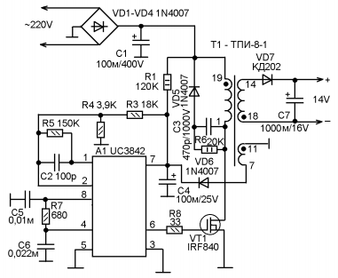
The initial power to start the integrated circuit A1 is supplied through the resistor R1, after which the pulse generator of the microcircuit is turned on, which outputs them to pin 6. Next, the pulses are fed to the gate of a powerful field-effect transistor VT1, opening it. The drain circuit of the transistor supplies power to the primary winding of the pulse transformer T1. After that, the transformer will turn on and the transmission of pulses to the secondary winding begins. The pulses of the secondary winding 7 - 11 after rectification by the VT6 diode are used to stabilize the operation of the A1 microcircuit, which in the full generation mode consumes much more current than it receives from the resistor R1 through the circuit.
In the event of a malfunction of the D6 diodes, the source switches to the pulsation mode, alternately starting the transformer and stopping it, while a characteristic pulsating “squeak” is heard, let's see the operation of the circuit in this mode.
Power through R1 and capacitor C4 start the chip's oscillator. After starting, a higher current is required for normal operation. If D6 fails, additional power is not supplied to the microcircuit, and generation stops, then the process repeats. If the diode D6 is working, it immediately turns on the pulse transformer under full load. During a normal start of the generator, a pulsed current of 12 - 14V appears on the winding 14-18 (at idle 15V). After rectification by the diode V7 and smoothing of the pulses by the capacitor C7, the pulsed current is supplied to the battery terminals.
A current of 100 mA does not harm the active component, but increases the recovery time by 3-4 times, reducing its time from 30 minutes to 1 hour. ( source — magazine Internet edition Radioconstructor 03-2013)
Quick Charger G4-1H RYOBI ONE+ BCL14181H
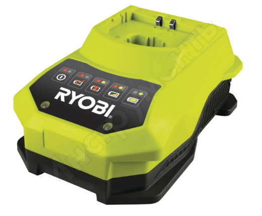 Pulse device for lithium batteries 18 volts manufactured by the German company Ryobi, manufacturer in the People's Republic of China. The pulse device is suitable for lithium-ion, nickel-cadmium 18V. It is designed for normal operation at temperatures from 0 to 50 C. The circuit solution provides two power supply modes for voltage and current stabilization. The pulsed current supply ensures optimal feeding of each individual battery.
The device is made in the original housing made of impact-resistant plastic. Forced cooling from a built-in fan is used, with automatic switching on when it reaches 40 ° C.
Characteristics:
- Minimum charge time 18V at 1.5 Ah - 60 minutes, weight 0.9 kg, dimensions: 210 x 86 x 174 mm. The charging process is indicated by a blue LED, and red when finished. There is a fault diagnosis that lights up when the assembly fails with a separate backlight on the case.
- Power supply single-phase 50Hz. 220V. The length of the network cable is 1.5 meters.
Charging station repair
If it happens that the product has ceased to perform its functions, it is best to contact specialized workshops, but elementary malfunctions can be fixed by hand. What to do if the power indicator is not on, let's analyze some simple malfunctions using the station as an example.
This product is designed to work with Li-ion batteries 12V, 1.8A. The product is made with a step-down transformer, the conversion of the reduced alternating current is performed by a four-diode bridge circuit. An electrolytic capacitor is installed to smooth out the ripple. From the indication there are LEDs for mains power, the beginning and end of saturation.
So, if the network indicator is off. First of all, it is necessary to verify the integrity of the primary winding circuit of the transformer through the mains plug. To do this, through the pins of the mains plug, you need to ring the integrity of the primary winding of the transformer with an ohmmeter by touching the probes of the device to the pins of the mains plug, if the circuit shows an open, then you need to inspect the parts inside the case.
A fuse break is possible, usually a thin wire stretched in a porcelain or glass case, which burns out during overloads. But some firms, for example, Interskol, in order to protect the transformer windings from overheating, install a thermal fuse between the turns of the primary winding, the purpose of which, when the temperature reaches 120 - 130 ° C, is to break the power supply circuit and, unfortunately, it is already after the break does not restore.
Typically, the fuse is located under the paper insulation of the primary winding, after opening which, you can easily find this part. To bring the circuit back into working condition, you can simply solder the ends of the winding into one piece, but you need to remember that the transformer remains without short circuit protection and it is best to install a conventional mains fuse instead of a thermal fuse.
If the primary winding circuit is intact, the secondary winding and bridge diodes ring out. For continuity of diodes, it is better to unsolder one end of the circuit and check the diode with an ohmmeter. When connecting the ends to the terminals of the probes in turn in one direction, the diode should show an open, in the other, a short circuit.
Thus, it is necessary to check all four diodes. And, if, indeed, we climbed into the circuit, then it is best to immediately change the capacitor, because the diodes are usually overloaded due to the excess electrolyte in the capacitor.
Buy power supplies for a screwdriver
Any hand tools and batteries can be purchased on our website. To do this, you need to go through a simple registration procedure and then follow the simple navigation. Simple site navigation will easily lead you to the tool you need. On the site you can see prices and compare them with competing stores. Any question that arises can be resolved with the help of the manager by calling the specified phone number or leaving the question to the specialist on duty. Come to us, and you will not be left without the choice of the tool you need.
I liked small chips for simple chargers. I bought them from us in a local offline store, but as luck would have it, they ended there, they were taken from somewhere for a long time. Looking at this situation, I decided to order them for myself in small bulk, since the microcircuits are pretty good, and I liked them in work.
Description and comparison under the cut.
It was not in vain that I wrote in the headline about the comparison, since during the journey the dog could grow up mikruhi appeared in the store, I bought several pieces and decided to compare them.
The review will not have a lot of text, but quite a lot of photos.
But I'll start, as always, with how it came to me.
It came complete with other different parts, the mikruhi themselves were packed in a bag with a latch and a sticker with the name. 
This microcircuit is a charger microcircuit for lithium batteries with a charge end voltage of 4.2 Volts.
It can charge batteries up to 800mA.
The current value is set by changing the value of the external resistor.
It also supports the function of charging with a small current if the battery is heavily discharged (voltage is lower than 2.9 Volts).
When charged to a voltage of 4.2 Volts and the charging current drops below 1/10 of the set value, the microcircuit turns off the charge. If the voltage drops to 4.05 Volts, then it will again go into charge mode.
There is also an output for connecting an indication LED.
More information can be found in, this chip has a much cheaper one.
Moreover, it is cheaper with us, on Ali the opposite is true.
Actually, for comparison, I bought an analogue. 
But what was my surprise when the LTC and STC microcircuits turned out to be completely identical in appearance, both were labeled LTC4054. 
Well, maybe even more interesting.
As everyone understands, it’s not so easy to check a microcircuit, it also needs a strapping from other radio components, preferably a board, etc.
And just then a friend asked to fix (although in this context it’s more likely to redo) a charger for 18650 batteries.
The native burned out, and the charge current was too small.
In general, for testing, you must first collect what we will test on.
I drew the board according to the datasheet, even without a diagram, but I will give the diagram here for convenience. 
Well, actually the printed circuit board. There are no diodes VD1 and VD2 on the board, they were added after everything. 
All this was printed out, transferred to a piece of textolite.
To save money, I made another board on pruning, a review with her participation will be later. 
Well, the printed circuit board was actually made and the necessary parts were selected. 
And I will remake such a charger, for sure it is very well known to readers. 
Inside it is a very complex circuit, consisting of a connector, an LED, a resistor and specially trained wires that allow you to equalize the charge on the batteries.
Just kidding, the charger is in a plug-in box, but here there are just 2 batteries connected in parallel and an LED permanently connected to the batteries.
We will return to the native charger later. 
I soldered the scarf, dug out the native board with the contacts, soldered the contacts with the springs themselves, they will still come in handy. 
I drilled a couple of new holes, on the middle there will be an LED indicating the device is turned on, in the side ones - the charging process. 
I soldered contacts with springs, as well as LEDs, into the new board.
It is convenient to first insert the LEDs into the board, then carefully install the board in its native place, and only after that solder it, then they will stand evenly and evenly. 

The board is installed in place, the power cable is soldered.
The printed circuit board itself was developed for three power supply options.
2 options with a MiniUSB connector, but in installation options on different sides of the board and under the cable.
In this case, at first I did not know how long the cable would be needed, so I soldered the short one.
I also soldered the wires going to the positive contacts of the batteries.
Now they go on separate wires, for each battery its own. 
Here's how it turned out from above. 
Well, now let's move on to testing.
On the left on the board, I installed the mikruha I bought on Ali, on the right I bought it offline.
Accordingly, they will be mirrored on top.
First mikruha with Ali.
Charge current. 
Now bought offline. 
Short circuit current.
Similarly, first with Ali. 
Now offline. 
There is a complete identity of the microcircuits, which, well, cannot but rejoice :)
It was noticed that at 4.8 Volts the charge current is 600mA, at 5 Volts it drops to 500, but this was checked after warming up, maybe this is how the overheating protection works, I have not figured it out yet, but the microcircuits behave approximately the same.
Well, now a little about the process of charging and finalizing the alteration (yes, it even happens).
From the very beginning, I thought to just set the LED to indicate the on state.
Everything seems to be simple and obvious.
But as always, I wanted more.
I decided that it would be better if it was extinguished during the charge process.
I soldered a couple of diodes (vd1 and vd2 in the diagram), but got a small bummer, the LED showing the charge mode shines even when there is no battery.
Rather, it doesn’t shine, but flickers quickly, I added a 47 microfarad capacitor parallel to the battery terminals, after which it began to flash very briefly, almost imperceptibly.
This is exactly the hysteresis for recharging if the voltage drops below 4.05 Volts.
In general, after this revision, everything was fine.
Battery charge, red is on, green is not on and the LED is not on where there is no battery. 
The battery is fully charged. 
In the off state, the microcircuit does not pass voltage to the power connector, and is not afraid of shorting this connector, so it does not discharge the battery to its LED. 
There was also no temperature measurement.
I got a little over 62 degrees after 15 minutes of charge. 
Well, this is what the finished device looks like.
External changes are minimal, unlike internal ones. A friend had a 5 / Volt 2 Amp power supply, and it was pretty good.
The device provides a charge current of 600mA per channel, the channels are independent. 
Well, it looked like a native charger. The comrade wanted to ask me to raise the charging current in it. It couldn’t stand the native either, where else to raise, slag. 
Summary.
In my opinion, for a microcircuit for 7 cents it is very good.
Chips are fully functional and are no different from those purchased offline.
I am very pleased, now there is a supply of mikruh and I don’t have to wait until they are in the store (recently they disappeared from sale again).
Of the minuses - This is not a finished device, so you have to etch, solder, etc., but there is a plus, you can make a board for a specific application, and not use what is.
Well, in a toga, getting a working product made by yourself is cheaper than ready-made boards, and even under your specific conditions.
I almost forgot, datasheet, diagram and trace -
All radio amateurs are well aware of charge boards for one can of li-ion batteries. It is in great demand due to its low price and good output parameters.


It is used to charge the previously mentioned batteries from a voltage of 5 volts. Such handkerchiefs are widely used in home-made designs with an autonomous power source in the form of lithium-ion batteries.
These controllers are produced in two versions - with and without protection. Those with protection are a bit expensive.
Protection performs several functions
1) Disconnects the battery during deep discharge, overcharging, overload and short circuit.

Today we will check this scarf in great detail and understand whether the parameters promised by the manufacturer correspond to the real ones, and we will also arrange other tests, let's go.
The board parameters are shown below
And these are the schemes, the upper one with protection, the lower one without
Under the microscope, it is noticeable that the board is of very good quality. Double-sided fiberglass, no "socks", silk-screen printing is present, all inputs and outputs are marked, it is not realistic to confuse the connection, if you are careful.

The microcircuit can provide a maximum charge current in the region of 1 Ampere, this current can be changed by selecting a resistor Rx (highlighted in red).
And this is a plate of the output current, depending on the resistance of the previously specified resistor.
The microcircuit sets the final charging voltage (about 4.2 Volts) and limits the charge current. The board has two LEDs, red and blue (colors may be different). The first one lights up during charging, the second one when the battery is fully charged.
There is a Micro USB connector, which is supplied with a voltage of 5 volts.
First test.
Let's check the output voltage to which the battery will be charged, it should be between 4.1 and 4.2V

That's right, no complaints.
Second test
Let's check the output current, on these boards the maximum current is set by default, and this is about 1A.
We will load the output of the board until the protection works, thus simulating a large consumption at the input or a discharged battery.
The maximum current is close to the declared one, let's move on.
Test 3
In place of the battery, a laboratory power supply is connected to which the voltage is pre-set in the region of 4 volts. We reduce the voltage until the protection turns off the battery, the multimeter displays the output voltage.

As you can see, at 2.4-2.5 volts, the output voltage disappeared, that is, the protection is working out. But this voltage is below critical, I think 2.8 Volts would be the most, in general, I do not advise discharging the battery to such an extent that the protection works.
Test 4
Checking the protection operation current.
For these purposes, an electronic load was used, we gradually increase the current.
The protection works at currents of about 3.5 Amperes (clearly visible in the video)
Of the shortcomings, I will only note that the microcircuit shamelessly heats up and even a heat-intensive board does not save, by the way - the microcircuit itself has a substrate for efficient heat transfer and this substrate is soldered to the board, the latter plays the role of a heat sink.


I think there is nothing to add, everyone saw it perfectly, the board is an excellent budget option when it comes to a charge controller for one can of Li-Ion battery of small capacity.
I think this is one of the most successful developments of Chinese engineers, which is available to everyone because of the negligible price.
Happy to stay!
It is difficult to evaluate the characteristics of a particular charger without understanding how the exemplary charge of a li-ion battery should actually flow. Therefore, before proceeding directly to the circuits, let's recall a little theory.
What are lithium batteries
Depending on what material the positive electrode of a lithium battery is made of, there are several varieties of them:
- with lithium cobaltate cathode;
- with cathode based on lithiated iron phosphate;
- based on nickel-cobalt-aluminum;
- based on nickel-cobalt-manganese.
All these batteries have their own characteristics, but since these nuances are not of fundamental importance for the general consumer, they will not be considered in this article.
Also, all li-ion batteries are produced in various sizes and form factors. They can be either in a case version (for example, the 18650 batteries that are popular today) or in a laminated or prismatic version (gel-polymer batteries). The latter are hermetically sealed bags made of a special film, in which the electrodes and the electrode mass are located.
The most common sizes of li-ion batteries are shown in the table below (they all have a nominal voltage of 3.7 volts):
| Designation | Size | Similar size |
|---|---|---|
| XXYY0, where XX- indication of the diameter in mm, YY- length value in mm, 0 - reflects the execution in the form of a cylinder |
10180 | 2/5 AAA |
| 10220 | 1/2 AAA (Ø corresponds to AAA, but half the length) | |
| 10280 | ||
| 10430 | AAA | |
| 10440 | AAA | |
| 14250 | 1/2AA | |
| 14270 | Ø AA, length CR2 | |
| 14430 | Ø 14 mm (like AA), but shorter | |
| 14500 | AA | |
| 14670 | ||
| 15266, 15270 | CR2 | |
| 16340 | CR123 | |
| 17500 | 150S/300S | |
| 17670 | 2xCR123 (or 168S/600S) | |
| 18350 | ||
| 18490 | ||
| 18500 | 2xCR123 (or 150A/300P) | |
| 18650 | 2xCR123 (or 168A/600P) | |
| 18700 | ||
| 22650 | ||
| 25500 | ||
| 26500 | FROM | |
| 26650 | ||
| 32650 | ||
| 33600 | D | |
| 42120 |
Internal electrochemical processes proceed in the same way and do not depend on the form factor and performance of the battery, so everything said below applies equally to all lithium batteries.
How to properly charge lithium-ion batteries
The most correct way to charge lithium batteries is to charge in two stages. It is this method that Sony uses in all its chargers. Despite the more complex charge controller, this provides a more complete charge of li-ion batteries without reducing their service life.
Here we are talking about a two-stage charge profile of lithium batteries, abbreviated as CC / CV (constant current, constant voltage). There are also options with pulsed and stepped currents, but they are not considered in this article. You can read more about charging with pulsed current.
So, let's consider both stages of the charge in more detail.
1. At the first stage a constant charge current must be provided. The current value is 0.2-0.5C. For accelerated charging, it is allowed to increase the current up to 0.5-1.0C (where C is the battery capacity).
For example, for a battery with a capacity of 3000 mAh, the nominal charge current in the first stage is 600-1500 mA, and the accelerated charge current can be in the range of 1.5-3A.
To ensure a constant charging current of a given value, the charger circuit (charger) must be able to raise the voltage at the battery terminals. In fact, at the first stage, the memory works like a classic current stabilizer.
Important: if you plan to charge batteries with a built-in protection board (PCB), then when designing the charger circuit, you must make sure that the open-circuit voltage of the circuit can never exceed 6-7 volts. Otherwise, the protection board may fail.
At the moment when the voltage on the battery rises to a value of 4.2 volts, the battery will gain approximately 70-80% of its capacity (the specific capacity value will depend on the charge current: with an accelerated charge it will be slightly less, with a nominal charge - a little more). This moment is the end of the first stage of the charge and serves as a signal for the transition to the second (and last) stage.
2. Second charge stage- this is the charge of the battery with a constant voltage, but gradually decreasing (falling) current.
At this stage, the charger maintains a voltage of 4.15-4.25 volts on the battery and controls the current value.
As the capacity increases, the charging current will decrease. As soon as its value decreases to 0.05-0.01С, the charging process is considered completed.
An important nuance in the operation of the correct charger is its complete disconnection from the battery after charging is completed. This is due to the fact that it is extremely undesirable for lithium batteries to be under high voltage for a long time, which is usually provided by the charger (i.e. 4.18-4.24 volts). This leads to accelerated degradation of the chemical composition of the battery and, as a result, a decrease in its capacity. Long stay means tens of hours or more.
During the second stage of the charge, the battery manages to gain about 0.1-0.15 more of its capacity. The total battery charge thus reaches 90-95%, which is an excellent indicator.
We have considered two main stages of charging. However, coverage of the issue of charging lithium batteries would be incomplete if one more stage of charging was not mentioned - the so-called. precharge.
Pre-charge stage (pre-charge)- this stage is used only for deeply discharged batteries (below 2.5 V) to bring them to normal operating mode.
At this stage, the charge is provided by a reduced constant current until the battery voltage reaches 2.8 V.
The preliminary stage is necessary to prevent swelling and depressurization (or even explosion with fire) of damaged batteries, which, for example, have an internal short circuit between the electrodes. If a large charge current is immediately passed through such a battery, this will inevitably lead to its heating, and then how lucky.
Another benefit of pre-charging is the pre-heating of the battery, which is important when charging at low ambient temperatures (in an unheated room during the cold season).
Intelligent charging should be able to monitor the voltage on the battery during the preliminary stage of charging and, if the voltage does not rise for a long time, to conclude that the battery is faulty.
All stages of charging a lithium-ion battery (including the pre-charge stage) are schematically shown in this graph: 
Exceeding the rated charging voltage by 0.15V can cut the battery life in half. Reducing the charge voltage by 0.1 volts reduces the capacity of a charged battery by about 10%, but significantly extends its life. The voltage of a fully charged battery after removing it from the charger is 4.1-4.15 volts.
To summarize the above, we outline the main theses:
1. What current to charge a li-ion battery (for example, 18650 or any other)?
The current will depend on how fast you would like to charge it and can range from 0.2C to 1C.
For example, for a 18650 battery with a capacity of 3400 mAh, the minimum charge current is 680 mA, and the maximum is 3400 mA.
2. How long does it take to charge, for example, the same 18650 rechargeable batteries?
The charge time directly depends on the charge current and is calculated by the formula:
T \u003d C / I charge.
For example, the charge time of our battery with a capacity of 3400 mAh with a current of 1A will be about 3.5 hours.
3. How to properly charge a lithium polymer battery?
All lithium batteries are charged in the same way. It doesn't matter if it's lithium polymer or lithium ion. For us consumers, there is no difference.
What is a protection board?
The protection board (or PCB - power control board) is designed to protect against short circuit, overcharge and overdischarge of the lithium battery. As a rule, overheating protection is also built into the protection modules.
For safety reasons, it is forbidden to use lithium batteries in household appliances if they do not have a built-in protection board. Therefore, all cell phone batteries always have a PCB board. The battery output terminals are located directly on the board: 
These boards use a six-legged charge controller on a specialized mikrukh (JW01, JW11, K091, G2J, G3J, S8210, S8261, NE57600, etc. analogues). The task of this controller is to disconnect the battery from the load when the battery is completely discharged and disconnect the battery from charging when it reaches 4.25V.
Here, for example, is a diagram of the BP-6M battery protection board that was supplied with old Nokia phones: 
If we talk about 18650, then they can be produced both with and without a protection board. The protection module is located in the area of the negative terminal of the battery. 

The board increases the length of the battery by 2-3 mm. 
Batteries without a PCB module usually come with batteries that come with their own protection circuits.
Any battery with protection can easily be converted into an unprotected battery by simply gutting it. ![]()
To date, the maximum capacity of the 18650 battery is 3400 mAh. Batteries with protection must have a corresponding designation on the case ("Protected"). 
Do not confuse PCB-board with PCM-module (PCM - power charge module). If the former serve only to protect the battery, then the latter are designed to control the charging process - they limit the charge current at a given level, control the temperature and, in general, ensure the entire process. The PCM board is what we call a charge controller.
I hope now there are no questions left, how to charge a 18650 battery or any other lithium battery? Then we turn to a small selection of ready-made circuit solutions for chargers (those same charge controllers).
Charging schemes for li-ion batteries
All circuits are suitable for charging any lithium battery, it remains only to decide on the charging current and element base.
LM317
Scheme of a simple charger based on the LM317 chip with a charge indicator: 
The circuit is simple, the whole setting comes down to setting the output voltage to 4.2 volts using the trimmer resistor R8 (without a connected battery!) And setting the charge current by selecting resistors R4, R6. The power of the resistor R1 is at least 1 watt.
As soon as the LED goes out, the charging process can be considered completed (the charging current will never decrease to zero). It is not recommended to keep the battery in this charge for a long time after it is fully charged.
The lm317 chip is widely used in various voltage and current stabilizers (depending on the switching circuit). It is sold on every corner and costs a penny in general (you can take 10 pieces for only 55 rubles).
LM317 comes in different cases: 
Pin assignment (pinout): 
The analogues of the LM317 chip are: GL317, SG31, SG317, UC317T, ECG1900, LM31MDT, SP900, KR142EN12, KR1157EN1 (the last two are domestic production).
Charging current can be increased up to 3A if you take LM350 instead of LM317. True, it will be more expensive - 11 rubles / piece.
The printed circuit board and circuit assembly are shown below: 

The old Soviet KT361 transistor can be replaced with a similar p-n-p transistor (for example, KT3107, KT3108 or bourgeois 2N5086, 2SA733, BC308A). It can be removed altogether if the charge indicator is not needed.
The disadvantage of the circuit: the supply voltage must be in the range of 8-12V. This is due to the fact that for the normal operation of the LM317 microcircuit, the difference between the battery voltage and the supply voltage must be at least 4.25 volts. Thus, it will not be possible to power it from the USB port.
MAX1555 or MAX1551
MAX1551/MAX1555 are specialized chargers for Li+ batteries that can work from USB or from a separate power adapter (for example, a phone charger).
 The only difference between these microcircuits is that MAX1555 gives a signal for the charge progress indicator, and MAX1551 - a signal that the power is on. Those. 1555 is still preferable in most cases, so 1551 is now hard to find on sale.
A detailed description of these chips from the manufacturer -.
The maximum input voltage from the DC adapter is 7 V, when powered from USB it is 6 V. When the supply voltage drops to 3.52 V, the microcircuit turns off and the charge stops.
The microcircuit itself detects at which input the supply voltage is present and is connected to it. If the power is supplied via the USB bus, then the maximum charge current is limited to 100 mA - this allows you to plug the charger into the USB port of any computer without fear of burning the south bridge.
When powered by a separate power supply, the typical charging current is 280mA.
The chips have built-in overheating protection. But even in this case, the circuit continues to work, reducing the charge current by 17mA for every degree above 110°C.
There is a pre-charge function (see above): as long as the battery voltage is below 3V, the microcircuit limits the charge current to 40 mA.
The microcircuit has 5 pins. Here is a typical wiring diagram: 
If there is a guarantee that the voltage at the output of your adapter cannot exceed 7 volts under any circumstances, then you can do without the 7805 stabilizer.
The USB charging option can be assembled, for example, on this one. 
The microcircuit does not need any external diodes or external transistors. In general, of course, chic mikruhi! Only they are too small, it is inconvenient to solder. And they are still expensive ().
LP2951
The LP2951 stabilizer is manufactured by National Semiconductors (). It provides the implementation of the built-in current limiting function and allows you to generate a stable level of charge voltage for a lithium-ion battery at the output of the circuit.
The charge voltage value is 4.08 - 4.26 volts and is set by resistor R3 when the battery is disconnected. The tension is very accurate.
The charge current is 150 - 300mA, this value is limited by the internal circuits of the LP2951 chip (depending on the manufacturer).
Use a diode with a small reverse current. For example, it can be any of the 1N400X series that you can get. The diode is used as a blocking diode to prevent reverse current from the battery to the LP2951 chip when the input voltage is turned off. 
This charger produces a fairly low charging current, so any 18650 battery can be charged all night.
The microcircuit can be bought both in a DIP package and in a SOIC package (the cost is about 10 rubles per piece).
MCP73831
The chip allows you to create the right chargers, besides, it is cheaper than the hyped MAX1555. 
A typical switching circuit is taken from: 
An important advantage of the circuit is the absence of low-resistance powerful resistors that limit the charge current. Here, the current is set by a resistor connected to the 5th output of the microcircuit. Its resistance should be in the range of 2-10 kOhm.
The charger assembly looks like this: 
The microcircuit heats up quite well during operation, but this does not seem to interfere with it. It performs its function.
Here is another pcb variant with smd led and micro usb connector: 
LTC4054 (STC4054)
Very simple, great idea! Allows charging with current up to 800 mA (see). True, it tends to get very hot, but in this case, the built-in overheat protection reduces the current. 
The circuit can be greatly simplified by throwing out one or even both LEDs with a transistor. Then it will look like this (agree, there is nowhere easier: a pair of resistors and one conder): 
One of the PCB options is available at . The board is designed for elements of size 0805.
I=1000/R. You should not set a large current right away, first see how much the microcircuit will heat up. For my purposes, I took a 2.7 kOhm resistor, while the charge current turned out to be about 360 mA.
It is unlikely that a radiator can be adapted to this microcircuit, and it is not a fact that it will be effective due to the high thermal resistance of the crystal-case transition. The manufacturer recommends making the heat sink "through the leads" - making the tracks as thick as possible and leaving the foil under the microcircuit case. And in general, the more "earth" foil left, the better.
By the way, most of the heat is removed through the 3rd leg, so you can make this track very wide and thick (fill it with excess solder). 
The LTC4054 chip package may be labeled LTH7 or LTADY.
LTH7 differs from LTADY in that the first one can lift a very dead battery (on which the voltage is less than 2.9 volts), while the second one cannot (you need to swing it separately).
Микросхема вышла очень удачной, поэтому имеет кучу аналогов: STC4054, MCP73831, TB4054, QX4054, TP4054, SGM4054, ACE4054, LP4054, U4054, BL4054, WPM4054, IT4504, Y1880, PT6102, PT6181, VS6102, HX6001, LC6000, LN5060, CX9058, EC49016, CYT5026, Q7051. Before using any of the analogues, check the datasheets.
TP4056
The microcircuit is made in the SOP-8 package (see), it has a metal heat sink on its belly that is not connected to the contacts, which makes it possible to more efficiently remove heat. Allows you to charge the battery with a current of up to 1A (the current depends on the current-setting resistor). 
The connection diagram requires the very minimum of attachments: 
The circuit implements the classic charge process - first charge with constant current, then with constant voltage and falling current. Everything is scientific. If you disassemble the charging step by step, then you can distinguish several stages:
- Monitoring the voltage of the connected battery (this happens all the time).
- Pre-charge stage (if the battery is discharged below 2.9 V). Charging current 1/10 from the programmed R prog resistor (100mA at R prog = 1.2 kOhm) to the level of 2.9 V.
- Charging with a maximum constant current (1000mA at R prog = 1.2 kOhm);
- When the battery reaches 4.2 V, the battery voltage is fixed at this level. A gradual decrease in the charging current begins.
- When the current reaches 1/10 of the R prog programmed by the resistor (100mA at R prog = 1.2 kOhm), the charger turns off.
- After charging is completed, the controller continues monitoring the battery voltage (see point 1). The current consumed by the monitoring circuit is 2-3 μA. After the voltage drops to 4.0V, charging turns on again. And so in a circle.
The charge current (in amperes) is calculated by the formula I=1200/R prog. The allowed maximum is 1000 mA.
A real test of charging with a 18650 battery at 3400 mAh is shown in the graph: 
The advantage of the microcircuit is that the charge current is set by only one resistor. Powerful low-resistance resistors are not required. Plus, there is an indicator of the charging process, as well as an indication of the end of charging. When the battery is not connected, the indicator blinks once every few seconds.
The supply voltage of the circuit must lie within 4.5 ... 8 volts. The closer to 4.5V - the better (so the chip heats up less).
The first leg is used to connect the temperature sensor built into the lithium-ion battery (usually the middle terminal of a cell phone battery). If the output voltage is below 45% or above 80% of the supply voltage, then charging is suspended. If you don't need temperature control, just put that foot on the ground.
Attention! This circuit has one significant drawback: the absence of a battery reverse protection circuit. In this case, the controller is guaranteed to burn out due to exceeding the maximum current. In this case, the supply voltage of the circuit directly falls on the battery, which is very dangerous.
The seal is simple, done in an hour on the knee. If time suffers, you can order ready-made modules. Some manufacturers of finished modules add protection against overcurrent and overdischarge (for example, you can choose which board you need - with or without protection, and with which connector). 
You can also find ready-made boards with a contact for a temperature sensor. Or even a charging module with multiple TP4056 chips in parallel to increase the charging current and with reverse polarity protection (example).
LTC1734
It's also a very simple design. The charge current is set by the resistor R prog (for example, if you put a 3 kΩ resistor, the current will be 500 mA).
Microcircuits are usually marked on the case: LTRG (they can often be found in old phones from Samsung). 
The transistor is suitable for any p-n-p in general, the main thing is that it is designed for a given charging current.
There is no charge indicator on this diagram, but on the LTC1734 it is said that pin "4" (Prog) has two functions - setting the current and monitoring the end of the battery charge. For example, a circuit with end-of-charge control using an LT1716 comparator is shown. 
The LT1716 comparator in this case can be replaced with a cheap LM358.
TL431 + transistor
It is probably difficult to come up with a circuit from more accessible components. Here the most difficult thing is to find the source of the reference voltage TL431. But they are so common that they are found almost everywhere (rarely what power source does without this microcircuit). 
Well, the TIP41 transistor can be replaced by any other with a suitable collector current. Even the old Soviet KT819, KT805 (or less powerful KT815, KT817) will do.
Setting up the circuit comes down to setting the output voltage (without a battery !!!) using a trimmer at a level of 4.2 volts. Resistor R1 sets the maximum value of the charging current.
This scheme fully implements the two-stage process of charging lithium batteries - first charging with direct current, then transition to the voltage stabilization phase and a smooth decrease in current to almost zero. The only drawback is the poor repeatability of the circuit (capricious in setting and demanding on the components used).
MCP73812
There is another undeservedly neglected microchip from Microchip - MCP73812 (see). Based on it, you get a very budget charging option (and inexpensive!). The whole kit is just one resistor!
By the way, the microcircuit is made in a case convenient for soldering - SOT23-5. 
The only negative is that it gets very hot and there is no charge indication. It also somehow does not work very reliably if you have a low-power power supply (which gives a voltage drop). 
In general, if charge indication is not important for you, and a current of 500 mA suits you, then the MCP73812 is a very good option.
NCP1835
A fully integrated solution is offered - NCP1835B, providing high stability of the charging voltage (4.2 ± 0.05 V).
Perhaps the only drawback of this microcircuit is its too small size (DFN-10 package, size 3x3 mm). Not everyone is able to provide high-quality soldering of such miniature elements. 
Of the indisputable advantages, I would like to note the following:
- The minimum number of body kit parts.
- Ability to charge a completely discharged battery (pre-charge current 30mA);
- Definition of the end of charging.
- Programmable charging current - up to 1000 mA.
- Charge and error indication (capable of detecting non-rechargeable batteries and signaling this).
- Long-term charge protection (by changing the capacitance of the capacitor C t, you can set the maximum charge time from 6.6 to 784 minutes).

The cost of the microcircuit is not that cheap, but not so large (~ $ 1) to refuse to use it. If you are friends with a soldering iron, I would recommend opting for this option.
A more detailed description is in .
Is it possible to charge a lithium-ion battery without a controller?
Yes, you can. However, this will require tight control over the charging current and voltage.
In general, it will not work to charge the battery, for example, our 18650 without a charger at all. You still need to somehow limit the maximum charge current, so at least the most primitive memory, but still required.
The simplest charger for any lithium battery is a resistor in series with the battery: 
The resistance and power dissipation of the resistor depend on the voltage of the power supply that will be used for charging.
Let's, as an example, calculate a resistor for a 5 volt power supply. We will charge a 18650 battery with a capacity of 2400 mAh.
So, at the very beginning of charging, the voltage drop across the resistor will be:
U r \u003d 5 - 2.8 \u003d 2.2 Volts
Suppose our 5V power supply is rated for a maximum current of 1A. The circuit will consume the largest current at the very beginning of the charge, when the voltage on the battery is minimal and is 2.7-2.8 Volts.
Attention: these calculations do not take into account the possibility that the battery can be very deeply discharged and the voltage on it can be much lower, down to zero.
Thus, the resistance of the resistor required to limit the current at the very beginning of the charge at the level of 1 Ampere should be:
R = U / I = 2.2 / 1 = 2.2 ohm
Resistor Dissipation Power:
P r \u003d I 2 R \u003d 1 * 1 * 2.2 \u003d 2.2 W
At the very end of the battery charge, when the voltage on it approaches 4.2 V, the charge current will be:
I charge \u003d (U un - 4.2) / R \u003d (5 - 4.2) / 2.2 \u003d 0.3 A
That is, as we can see, all values do not go beyond the allowable limits for a given battery: the initial current does not exceed the maximum allowable charge current for a given battery (2.4 A), and the final current exceeds the current at which the battery no longer gains capacity ( 0.24 A).
The main disadvantage of such charging is the need to constantly monitor the voltage on the battery. And manually turn off the charge as soon as the voltage reaches 4.2 Volts. The fact is that lithium batteries do not tolerate even a short-term overvoltage very well - the electrode masses begin to degrade quickly, which inevitably leads to a loss of capacity. At the same time, all the prerequisites for overheating and depressurization are created.
If your battery has a built-in protection board, which was discussed a little higher, then everything is simplified. Upon reaching a certain voltage on the battery, the board itself will disconnect it from the charger. However, this method of charging has significant disadvantages, which we talked about in.
The protection built into the battery will not allow it to be recharged under any circumstances. All that remains for you to do is to control the charge current so that it does not exceed the allowable values \u200b\u200bfor this battery (protection boards cannot limit the charge current, unfortunately).
Charging with a laboratory power supply
If you have a power supply with current protection (limitation) at your disposal, then you are saved! Such a power supply is already a full-fledged charger that implements the correct charge profile, which we wrote about above (CC / CV).
 All you need to do to charge li-ion is to set the power supply to 4.2 volts and set the desired current limit. And you can connect the battery.
Initially, when the battery is still discharged, the laboratory power supply will operate in current protection mode (i.e., it will stabilize the output current at a given level). Then, when the voltage on the bank rises to the set 4.2V, the power supply will switch to voltage stabilization mode, and the current will begin to fall.
When the current drops to 0.05-0.1C, the battery can be considered fully charged.
As you can see, the laboratory PSU is an almost perfect charger! The only thing it can't do automatically is make a decision to fully charge the battery and turn off. But this is a trifle, which is not even worth paying attention to.
How to charge lithium batteries?
And if we are talking about a disposable battery that is not intended for recharging, then the correct (and only correct) answer to this question is NO.
The fact is that any lithium battery (for example, the common CR2032 in the form of a flat tablet) is characterized by the presence of an internal passivating layer that covers the lithium anode. This layer prevents the anode from reacting chemically with the electrolyte. And the supply of external current destroys the above protective layer, leading to damage to the battery.
By the way, if we talk about the CR2032 non-rechargeable battery, that is, the LIR2032, which is very similar to it, is already a full-fledged battery. It can and should be recharged. Only her voltage is not 3, but 3.6V.
How to charge lithium batteries (whether it's a phone battery, 18650 or any other li-ion battery) was discussed at the beginning of the article.