The main indicator of the quality of each antenna is its interaction with the air signal. This principle of operation underlies both purchased and homemade antennas. We suggest that you familiarize yourself with recommendations on how to make an antenna for digital TV with your own hands.
Features of modern television
If you compare modern television broadcasts with the broadcasts that existed several years ago, you can find certain differences. First of all, the UHF range is used for television broadcasting. Thus, it is possible to significantly save money and signal reception by the antenna. In addition, in this case, there is also no need for periodic maintenance of antennas.
Also, there are many more television sensors than before, so most television channels are available in almost all places in the country. To ensure television broadcasting in habitable areas, low-power sensors are used.
In big cities, radio waves travel differently. Due to the large number of multi-story buildings, the signal through them is weak. In addition, there are a huge number of television channels, for which one standard television antenna is not enough to receive.
With development digital broadcasting Receiving channels has become even easier. These types of antennas are distinguished by their resistance to interference, phase or cable distortion, and image clarity.
Simple DIY digital antenna: device requirements
Since television broadcasting conditions have changed, the rules for operating modern antennas have also changed:
1. One of the main parameters of a television antenna, in the form of directional coefficient and protection coefficient, are not particularly important. To combat various types of interference, various electronic means are used.
2. The coefficient responsible for the antenna gain improves the signal, clears it of extraneous sounds and various kinds of interference.
3. Another important quality of a modern television antenna is range. Electrical parameters are saved automatically, without additional human intervention.
4. The operating range of the television antenna should interact well with the cable that connects to the antenna.
5. To avoid the appearance of phase distortions, it is necessary to ensure decent antenna characteristics in the amplitude-frequency ratio.
The characteristics of the last three points are determined by the properties of receiving a television signal using an antenna. An antenna operating at one frequency is capable of receiving several wave channels. However, in order for them to be consistent with the feeder, it is necessary to have a USS that strongly absorbs signals.
Therefore, there are certain options for digital antennas available for making at home. We suggest you familiarize yourself with them:
1. All-wave version of the antenna, such devices are frequency independent, they are cheap, and very popular among consumers. One hour is enough to make such an antenna. Such an antenna is perfect for city apartments, but in a populated area that is somewhat distant from television centers, such an antenna will work worse.
2. Speech therapy band version of the antenna - such an antenna picks up certain signals. It has a simple design, is well suited for various operating ranges, and does not change the feeder parameters. It has average technical parameters and is excellent for country houses, dachas, and apartments.
3. Z-shaped antenna, which is also called a zigzag antenna. Making such a structure will require a lot of time and physical effort. It has wide receiving characteristics. With the help of such an antenna it is possible to expand the reception range of television channels.
To achieve precise matching between antennas, it is necessary to lay the cable across the zero potential value.
DIY digital TV antenna: reception characteristics
Vibraton antennas are capable of finding several more digital ones on one analog cantal. Such devices receive wave channels. They are rarely used and are relevant for places remote from television towers.
Making your own satellite dish is a pointless process. Since in this process you will need to purchase a commercial tuner and head, and the alignment of the mirrors must be very accurate, it is almost impossible to achieve it at home. You can only configure such an antenna yourself, but not manufacture it.
In order to make the above antenna options, you need to have a very good understanding of higher mathematics and electrodynamic processes. Among the main characteristics of the terms used in the manufacturing process of television antennas, we note:
1. KU - antenna power, which is determined in the ratio of the received antenna signal to its main lobe.
2. KND - the relationship between the solid circle and the solid angle of the antenna lobes. If there are lobes of different sizes, they change in area.
3. KZD - the ratio between the signal received at the main lobe and the total amount of antenna power.
Please note that if the antenna is a band antenna, then the power is taken into account in relation to the useful signal.
Note that the first two terms are not necessarily interdependent. There are certain antenna options that have high directivity, but unity or less gain. However, a zigzag antenna combines significant gain with a low directivity level.

DIY digital TV antenna: manufacturing technology
Each of the antenna elements, through which the current flows, supplying the useful signal, must be connected to the other by soldering or welding. Any prefabricated unit located outdoors must be well fixed, since the destruction of electronic contact on the street occurs faster than indoors.
Particular attention should be paid to zero potential. It is in these places that voltage nodes and electric current are located at its highest power. Solid bent metal is used to make zero-potential locations.
The braid or core is made from coaxial cable made from copper or an inexpensive alloy with anti-corrosion properties. To solder the cable, a forty-volt soldering machine is used, with low-melting solders and flux paste.
A do-it-yourself outdoor digital antenna is made in such a way that all connections are resistant to moisture, temperature changes and other environmental influences.

To make an all-wave antenna you will need two triangular plates, two slats made of wood and enameled wire. At the same time, the size of the wire in diameter is practically unimportant, and the interval between their ends is about 2-3 cm. The interval between the plates on which the ends of the wire are located is 1 cm. One-sided square-shaped fiberglass coated with foil can replace two metal plates. At the same time, copper triangles should be cut out on it.
The antenna's width should be the same as its height. The canvases open at right angles. In order to lay the cable to this antenna, you must follow a certain diagram. The cable braid is not soldered to the point indicating zero potential. She just gets attached to her.
The CHNA, which stretches 150 cm inside the window, is capable of receiving most meter and DCM channels of any direction. The advantage of this antenna is that it has a wide channel reception interval. Therefore, such antennas are popular in big cities, where there are various television centers. However, such an antenna has certain disadvantages - the antenna gain is single, and the gain is zero. Therefore, in the presence of large interference, the antenna will be irrelevant.
It is possible to make other types of digital antennas with your own hands using CNA, for example, a logarithmic spiral of two turns. This version of the antenna is compact and easier to manufacture.
Over-the-air digital antennas made from beer cans
To make a digital antenna with your own hands from a cable, you will need beer cans. This version of the antenna, with the right approach to its manufacture, has good performance characteristics. In addition, such an antenna is quite simple to manufacture.
The operating principle of such an antenna is based on increasing the diameter of the arms on a conventional linear vibrator. In this case, the working band expands, while other properties do not change.
Beer cans, in proportion to their size, are used as arms on the vibrator. At the same time, the expansion of the shoulders is unlimited. This version of a simple vibrator is used as an indoor digital antenna with your own hands to receive television broadcasts by connecting directly via cable.
If you choose the option of assembling a common-mode grating from a beer diopole, located vertically, with a step of half a wave, you will be able to improve the gain value of the antenna. Also, this device must have an antenna amplifier installed, with the help of which the device is coordinated and configured.

To strengthen such an antenna, a CPD is added to it, a screen and a grid are installed on the back of it, with an interval of half a grid. To install a beer antenna, you will need a dielectric mast, while the screen and the mast are connected by a mechanical connection.
At the same time, about three or four rows are arranged on the grid. Two gratings are not capable of achieving high gain.
DIY UHF antenna for digital television
A log-periodic version of the antenna is called a prefabricated antenna, which is connected to the halves on a linear diopole, the interval between them varies in relation to the geometric parameters of the progression. There are configured and free lines. We suggest choosing a longer and smoother version of the antenna.
To manufacture LPA, it is necessary to have any predetermined range. The higher the progression indicators, the greater the gain of the antenna. This antenna option in terms of operational and technical specifications is ideal for making at home.
The main principle of its normal functioning is making correct calculations. With increasing progressive indicators, the gain increases and the directivity angle decreases. This antenna does not require an additional screen. Since it does not depend on its general characteristics.

When calculating a digital LP antenna, use the following recommendations:
- the second longest vibrator must have a reserve of frequency power;
- Next, the longest diopole is calculated;
- After this, another specified frequency range is added.
If the shortest diopole leaves lines, then it is cut off, since it is needed on the antenna only for calculations. The total length of the antenna will be about 40 cm.
The diameter of the lines on the antenna is about 7-16 mm. In this case, the interval between the axes is 40 mm. The cable is not tied to the line externally, as this will negatively affect the technical properties of the antenna.
The outdoor antenna is fixed to the mast using the center of gravity. Otherwise, the antenna will constantly shake under the influence of the wind. However, the metal mast is not connected to the line in a straight line, since a dielectric mast, the length of which is about 150 cm, must be provided in this place. A wooden beam, previously painted or varnished, can be used as a dielectric material.
DIY digital antenna video:
Once upon a time, a good television antenna was in short supply; purchased ones did not differ in quality and durability, to put it mildly. Making an antenna for a “box” or “coffin” (an old tube TV) with your own hands was considered a sign of skill. Interest in homemade antennas continues to this day. There is nothing strange here: the conditions for TV reception have changed dramatically, and manufacturers, believing that there is and will not be anything significantly new in the theory of antennas, most often adapt electronics to long-known designs, without thinking about the fact that The main thing for any antenna is its interaction with the signal on the air.
What has changed on air?
Firstly, almost the entire volume of TV broadcasting is currently carried out in the UHF range. First of all, for economic reasons, it greatly simplifies and reduces the cost of the antenna-feeder system of transmitting stations, and, more importantly, the need for its regular maintenance by highly qualified specialists engaged in hard, harmful and dangerous work.
Second - TV transmitters now cover almost all more or less populated areas with their signal, and a developed communication network ensures the delivery of programs to the most remote corners. There, broadcasting in the habitable zone is provided by low-power, unattended transmitters.
Third, the conditions for the propagation of radio waves in cities have changed. On the UHF, industrial interference leaks in weakly, but reinforced concrete high-rise buildings are good mirrors for them, repeatedly reflecting the signal until it is completely attenuated in an area of seemingly reliable reception.
Fourth - There are a lot of TV programs on air now, dozens and hundreds. How diverse and meaningful this set is is another question, but counting on receiving 1-2-3 channels is now pointless.
Finally, digital broadcasting has developed. The DVB T2 signal is a special thing. Where it still exceeds the noise even just a little, by 1.5-2 dB, the reception is excellent, as if nothing had happened. But a little further or to the side - no, it’s cut off. Digital is almost insensitive to interference, but if there is a mismatch with the cable or phase distortion anywhere in the path, from the camera to the tuner, the picture can crumble into squares even with a strong clean signal.
Antenna requirements
In accordance with the new reception conditions, the basic requirements for TV antennas have also changed:
- Its parameters such as the directivity coefficient (DAC) and the protective action coefficient (PAC) are now of no decisive importance: modern air is very dirty, and along the tiny side lobe of the directional pattern (DP), at least some interference will get through, and You need to fight it using electronic means.
- In return, the antenna's own gain (GA) becomes especially important. An antenna that catches the air well, rather than looking at it through a small hole, will provide a reserve of power for the received signal, allowing the electronics to clear it of noise and interference.
- A modern television antenna, with rare exceptions, must be a range antenna, i.e. its electrical parameters must be preserved naturally, at the level of theory, and not squeezed into acceptable limits through engineering tricks.
- The TV antenna must be matched with the cable over its entire operating frequency range without additional matching and balancing devices (MCD).
- The amplitude-frequency response of the antenna (AFC) should be as smooth as possible. Sharp surges and dips are certainly accompanied by phase distortions.
The last 3 points are determined by the requirements for receiving digital signals. Customized, i.e. Working theoretically at the same frequency, antennas can be “stretched” in frequency, for example. antennas of the “wave channel” type on the UHF with an acceptable signal-to-noise ratio capture channels 21-40. But their coordination with the feeder requires the use of USSs, which either strongly absorb the signal (ferrite) or spoil the phase response at the edges of the range (tuned). And such an antenna, which works perfectly on analogue, will receive “digital” poorly.
In this regard, from all the great variety of antennas, this article will consider TV antennas, available for self-production, of the following types:
- Frequency independent (all-wave)– does not have high parameters, but is very simple and cheap, it can be done in literally an hour. Outside the city, where the airwaves are cleaner, it will be able to receive digital or a fairly powerful analogue not a short distance from the television center.
- Range log-periodic. Figuratively speaking, it can be likened to a fishing trawl, which sorts the prey during fishing. It is also quite simple, fits perfectly with the feeder throughout its entire range, and does not change its parameters at all. The technical parameters are average, so it is more suitable for a summer residence, and in the city as a room.
- Several modifications of the zigzag antenna, or Z-antennas. In the MV range, this is a very solid design that requires considerable skill and time. But on the UHF, due to the principle of geometric similarity (see below), it is so simplified and shrunk that it can well be used as a highly efficient indoor antenna under almost any reception conditions.
Note: The Z-antenna, to use the previous analogy, is a frequent flyer that scoops up everything in the water. As the air became littered, it fell out of use, but with the development of digital TV, it was once again on the high horse - throughout its entire range, it is just as perfectly coordinated and keeps the parameters as a “speech therapist.”
Precise matching and balancing of almost all antennas described below is achieved by laying the cable through the so-called. zero potential point. It has special requirements, which will be discussed in more detail below.
About vibrator antennas
In the frequency band of one analog channel, up to several dozen digital ones can be transmitted. And, as already said, the digital works with an insignificant signal-to-noise ratio. Therefore, in places very remote from the television center, where the signal of one or two channels barely reaches, the good old wave channel (AVK, wave channel antenna), from the class of vibrator antennas, can be used for receiving digital TV, so at the end we will devote a few lines and to her.
About satellite reception
There is no point in making a satellite dish yourself. You still need to buy a head and a tuner, and behind the external simplicity of the mirror lies a parabolic surface of oblique incidence, which not every industrial enterprise can produce with the required accuracy. The only thing homemade people can do is set up a satellite dish, about that.
About antenna parameters
Accurate determination of the antenna parameters mentioned above requires knowledge of higher mathematics and electrodynamics, but it is necessary to understand their meaning when starting to manufacture an antenna. Therefore, we will give somewhat rough, but still clarifying definitions (see figure on the right):

- KU is the ratio of the signal power received by the antenna on the main (main) lobe of its DP to its same power received in the same place and at the same frequency by an omnidirectional, circular, DP antenna.
- KND is the ratio of the solid angle of the entire sphere to the solid angle of the opening of the main lobe of the DN, assuming that its cross section is a circle. If the main petal has different sizes in different planes, you need to compare the area of the sphere and its cross-sectional area of the main petal.
- SCR is the ratio of the signal power received at the main lobe to the sum of the interference powers at the same frequency received by all secondary (back and side) lobes.
Notes:
- If the antenna is a band antenna, the powers are calculated at the frequency of the useful signal.
- Since there are no completely omnidirectional antennas, a half-wave linear dipole oriented in the direction of the electric field vector (according to its polarization) is taken as such. Its QU is considered equal to 1. TV programs are transmitted with horizontal polarization.
It should be remembered that CG and KNI are not necessarily interrelated. There are antennas (for example, “spy” - single-wire traveling wave antenna, ABC) with high directivity, but single or lower gain. These look into the distance as if through a diopter sight. On the other hand, there are antennas, e.g. Z-antenna, which combines low directivity with significant gain.
About the intricacies of manufacturing
All antenna elements through which useful signal currents flow (specifically, in the descriptions of individual antennas) must be connected to each other by soldering or welding. In any prefabricated unit in the open air, the electrical contact will soon be broken, and the parameters of the antenna will deteriorate sharply, up to its complete unusability.
This is especially true for points of zero potential. In them, as experts say, there is a voltage node and a current antinode, i.e. its greatest value. Current at zero voltage? Nothing surprising. Electrodynamics has moved as far from Ohm's law on direct current as the T-50 has gone from a kite.
Places with zero potential points for digital antennas are best made bent from solid metal. A small “creeping” current in welding when receiving the analogue in the picture will most likely not affect it. But, if a digital signal is received at the noise level, then the tuner may not see the signal due to the “creep”. Which, with pure current at the antinode, would give stable reception.
About cable soldering
The braid (and often the central core) of modern coaxial cables is made not of copper, but of corrosion-resistant and inexpensive alloys. They solder poorly and if you heat them for a long time, you can burn out the cable. Therefore, you need to solder the cables with a 40-W soldering iron, low-melting solder and with flux paste instead of rosin or alcohol rosin. There is no need to spare the paste; the solder immediately spreads along the veins of the braid only under a layer of boiling flux.

Types of antennas
All-wave
An all-wave (more precisely, frequency-independent, FNA) antenna is shown in Fig. It consists of two triangular metal plates, two wooden slats, and a lot of enameled copper wires. The diameter of the wire does not matter, and the distance between the ends of the wires on the slats is 20-30 mm. The gap between the plates to which the other ends of the wires are soldered is 10 mm.
Note: Instead of two metal plates, it is better to take a square of one-sided foil fiberglass with triangles cut out of copper.
The width of the antenna is equal to its height, the opening angle of the blades is 90 degrees. The cable routing diagram is shown there in Fig. The point marked in yellow is the point of quasi-zero potential. There is no need to solder the cable braid to the fabric in it, just tie it tightly, and the capacity between the braid and the fabric will be enough for matching.
The CHNA, stretched in a window 1.5 m wide, receives all meter and DCM channels from almost all directions, except for a dip of about 15 degrees in the plane of the canvas. This is its advantage in places where it is possible to receive signals from different television centers; it does not need to be rotated. Disadvantages - single gain and zero gain, therefore, in the interference zone and outside the zone of reliable reception, the CNA is not suitable.
Note : There are other types of CNA, for example. in the form of a two-turn logarithmic spiral. It is more compact than the CNA made of triangular sheets in the same frequency range, therefore it is sometimes used in technology. But in everyday life this does not provide any advantages, it is more difficult to make a spiral CNA, and it is more difficult to coordinate with a coaxial cable, so we are not considering it.
Based on the CHNA, the once very popular fan vibrator (horns, flyer, slingshot) was created, see fig. Its directivity factor and coefficient of performance are something around 1.4 with a fairly smooth frequency response and linear phase response, so it would be suitable for digital use even now. But - it works only on HF (channels 1-12), and digital broadcasting is on UHF. However, in the countryside, with an elevation of 10-12 m, it may be suitable for receiving an analogue. Mast 2 can be made of any material, but fastening strips 1 are made of a good non-wetting dielectric: fiberglass or fluoroplastic with a thickness of at least 10 mm.

Beer all-wave

The all-wave antenna made from beer cans is clearly not the fruit of the hangover hallucinations of a drunken radio amateur. This is truly a very good antenna for all reception situations, you just need to do it right. And it’s extremely simple.
Its design is based on the following phenomenon: if you increase the diameter of the arms of a conventional linear vibrator, then its operating frequency band expands, but other parameters remain unchanged. In long-distance radio communications, since the 20s, the so-called Nadenenko's dipole based on this principle. And beer cans are just the right size to serve as the arms of a vibrator on the UHF. In essence, the CHNA is a dipole, the arms of which expand indefinitely to infinity.
The simplest beer vibrator made of two cans is suitable for indoor analogue reception in the city, even without coordination with the cable, if its length is no more than 2 m, on the left in Fig. And if you assemble a vertical in-phase array from beer dipoles with a step of half a wave (on the right in the figure), match it and balance it using an amplifier from a Polish antenna (we will talk about it later), then thanks to the vertical compression of the main lobe of the pattern, such an antenna will give good CU.
The gain of the “tavern” can be further increased by adding a CPD at the same time, if a mesh screen is placed behind it at a distance equal to half the grid pitch. The beer grill is mounted on a dielectric mast; The mechanical connections between the screen and the mast are also dielectric. The rest is clear from the following. rice.

Note: the optimal number of lattice floors is 3-4. With 2, the gain in gain will be small, and more is difficult to coordinate with the cable.
Video: making a simple antenna from beer cans
"Speech therapist"
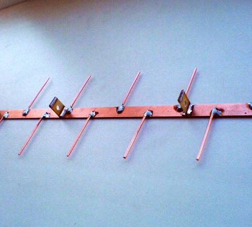
A log-periodic antenna (LPA) is a collecting line to which halves of linear dipoles (i.e., pieces of conductor a quarter of the operating wavelength) are alternately connected, the length and distance between which vary in geometric progression with an index less than 1, in the center in Fig. The line can be either configured (with a short circuit at the end opposite to the cable connection) or free. An LPA on a free (unconfigured) line is preferable for digital reception: it comes out longer, but its frequency response and phase response are smooth, and the matching with the cable does not depend on frequency, so we will focus on it.

The LPA can be manufactured for any predetermined frequency range, up to 1-2 GHz. When the operating frequency changes, its active region of 1-5 dipoles moves back and forth along the canvas. Therefore, the closer the progression indicator is to 1, and accordingly the smaller the antenna opening angle, the greater the gain it will give, but at the same time its length increases. At UHF, 26 dB can be achieved from an outdoor LPA, and 12 dB from a room LPA.
LPA can be said to be an ideal digital antenna based on its totality of qualities, so let’s look at its calculation in a little more detail. The main thing you need to know is that an increase in the progression indicator (tau in the figure) gives an increase in gain, and a decrease in the LPA opening angle (alpha) increases the directivity. A screen is not needed for the LPA; it has almost no effect on its parameters.
Calculation of digital LPA has the following features:
- They start it, for the sake of frequency reserve, with the second longest vibrator.
- Then, taking the reciprocal of the progression index, the longest dipole is calculated.
- After the shortest dipole based on the given frequency range, another one is added.
Let's explain with an example. Let's say our digital programs are in the range of 21-31 TVK, i.e. at 470-558 MHz in frequency; wavelengths, respectively, are 638-537 mm. Let’s also assume that we need to receive a weak noisy signal far from the station, so we take the maximum (0.9) progression rate and the minimum (30 degrees) opening angle. For the calculation, you will need half the opening angle, i.e. 15 degrees in our case. The opening can be further reduced, but the length of the antenna will increase exorbitantly, in cotangent terms.
We consider B2 in Fig: 638/2 = 319 mm, and the arms of the dipole will be 160 mm each, you can round up to 1 mm. The calculation will need to be carried out until you get Bn = 537/2 = 269 mm, and then calculate another dipole.
Now we consider A2 as B2/tg15 = 319/0.26795 = 1190 mm. Then, through the progression indicator, A1 and B1: A1 = A2/0.9 = 1322 mm; B1 = 319/0.9 = 354.5 = 355 mm. Next, sequentially, starting with B2 and A2, we multiply by the indicator until we reach 269 mm:
- B3 = B2*0.9 = 287 mm; A3 = A2*0.9 = 1071 mm.
- B4 = 258 mm; A4 = 964 mm.
Stop, we are already less than 269 mm. We check whether we can meet the gain requirements, although it is clear that we can’t: to get 12 dB or more, the distances between the dipoles should not exceed 0.1-0.12 wavelengths. In this case, for B1 we have A1-A2 = 1322 – 1190 = 132 mm, which is 132/638 = 0.21 wavelengths of B1. We need to “pull up” the indicator to 1, to 0.93-0.97, so we try different ones until the first difference A1-A2 is reduced by half or more. For a maximum of 26 dB, you need a distance between dipoles of 0.03-0.05 wavelengths, but not less than 2 dipole diameters, 3-10 mm at UHF.
Note: cut off the rest of the line behind the shortest dipole; it is needed only for calculations. Therefore, the actual length of the finished antenna will be only about 400 mm. If our LPA is external, this is very good: we can reduce the opening, obtaining greater directionality and protection from interference.
Video: antenna for digital TV DVB T2
About the line and the mast
The diameter of the tubes of the LPA line on the UHF is 8-15 mm; the distance between their axes is 3-4 diameters. Let’s also take into account that thin “lace” cables give such attenuation per meter on the UHF that all antenna-amplification tricks will come to naught. You need to take a good coaxial for an outdoor antenna, with a shell diameter of 6-8 mm. That is, the tubes for the line must be thin-walled, seamless. You cannot tie the cable to the line from the outside; the quality of the LPA will drop sharply.
It is necessary, of course, to attach the outer propulsion boat to the mast by the center of gravity, otherwise the small windage of the propulsion craft will turn into a huge and shaking one. But it is also impossible to connect a metal mast directly to the line: you need to provide a dielectric insert of at least 1.5 m in length. The quality of the dielectric does not play a big role here; oiled and painted wood will do.
About the Delta antenna
If the UHF LPA is consistent with the cable amplifier (see below, about Polish antennas), then the arms of a meter dipole, linear or fan-shaped, like a “slingshot”, can be attached to the line. Then we will get a universal VHF-UHF antenna of excellent quality. This solution is used in the popular Delta antenna, see fig.

Antenna “Delta”
Zigzag on air
A Z-antenna with a reflector gives the same gain and gain as the LPA, but its main lobe is more than twice as wide horizontally. This can be important in rural areas when there is TV reception from different directions. And the decimeter Z-antenna has small dimensions, which is essential for indoor reception. But its operating range is theoretically not unlimited; frequency overlap while maintaining parameters acceptable for the digital range is up to 2.7.

The design of the MV Z-antenna is shown in Fig; The cable route is highlighted in red. There in the lower left there is a more compact ring version, colloquially known as a “spider”. It clearly shows that the Z-antenna was born as a combination of a CNA with a range vibrator; There is also something of a rhombic antenna in it, which does not fit into the theme. Yes, the “spider” ring does not have to be wooden, it can be a metal hoop. "Spider" receives 1-12 MV channels; The pattern without a reflector is almost circular.
The classic zigzag works either on 1-5 or 6-12 channels, but for its manufacture you only need wooden slats, enameled copper wire with d = 0.6-1.2 mm and several scraps of foil fiberglass, so we give the dimensions in fraction for 1-5/6-12 channels: A = 3400/950 mm, B, C = 1700/450 mm, b = 100/28 mm, B = 300/100 mm. At point E there is zero potential; here you need to solder the braid to a metallized support plate. Reflector dimensions, also 1-5/6-12: A = 620/175 mm, B = 300/130 mm, D = 3200/900 mm.
The range Z-antenna with a reflector gives a gain of 12 dB, tuned to one channel - 26 dB. To build a single-channel one based on a band zigzag, you need to take the side of the square of the canvas in the middle of its width at a quarter of the wavelength and recalculate all other dimensions proportionally.
Folk Zigzag
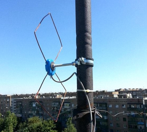
As you can see, the MV Z-antenna is a rather complex structure. But its principle shows itself in all its glory on the UHF. The UHF Z-antenna with capacitive inserts, combining the advantages of the “classics” and the “spider”, is so easy to make that even in the USSR it earned the title of folk antenna, see fig.

Material – copper tube or aluminum sheet with a thickness of 6 mm. The side squares are solid metal or covered with mesh, or covered with a tin. In the last two cases, they need to be soldered along the circuit. The coax cannot be bent sharply, so we guide it so that it reaches the side corner, and then does not go beyond the capacitive insert (side square). At point A (zero potential point), we electrically connect the cable braid to the fabric.
Note: aluminum cannot be soldered with conventional solders and fluxes, so “folk” aluminum is suitable for outdoor installation only after sealing the electrical connections with silicone, since everything in it is screwed.
Video: example of a double triangle antenna
Wave channel

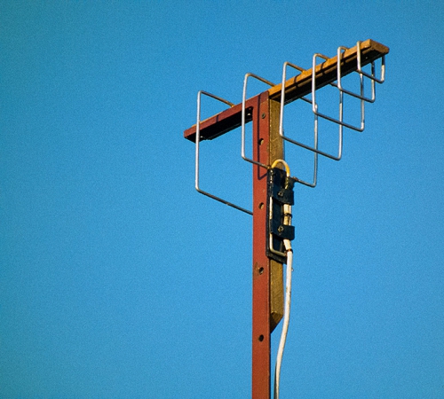
The wave channel antenna (AWC), or Udo-Yagi antenna, available for self-production, is capable of giving the highest gain, directivity factor and efficiency factor. But it can only receive digital signals on UHF on 1 or 2-3 adjacent channels, because belongs to the class of highly tuned antennas. Its parameters deteriorate sharply beyond the tuning frequency. It is recommended to use AVK under very poor reception conditions, and make a separate one for each TVK. Fortunately, this is not very difficult - AVK is simple and cheap.
The operation of the AVK is based on “raking” the electromagnetic field (EMF) of the signal to the active vibrator. Externally small, lightweight, with minimal windage, the AVK can have an effective aperture of dozens of wavelengths of the operating frequency. Directors (directors) that are shortened and therefore have capacitive impedance (impedance) direct the EMF to the active vibrator, and the reflector (reflector), elongated, with inductive impedance, throws back to it what has slipped past. Only 1 reflector is needed in an AVK, but there can be from 1 to 20 or more directors. The more there are, the higher the gain of the AVC, but the narrower its frequency band.
From interaction with the reflector and directors, the wave impedance of the active (from which the signal is taken) vibrator drops the more, the closer the antenna is tuned to the maximum gain, and coordination with the cable is lost. Therefore, the active dipole AVK is made into a loop, its initial wave impedance is not 73 Ohms, like a linear one, but 300 Ohms. At the cost of reducing it to 75 Ohms, an AVK with three directors (five-element, see the figure on the right) can be adjusted to almost a maximum gain of 26 dB. A characteristic pattern for AVK in the horizontal plane is shown in Fig. at the beginning of the article.
AVK elements are connected to the boom at points of zero potential, so the mast and boom can be anything. Propylene pipes work very well.
Calculation and adjustment of AVK for analog and digital are somewhat different. For analogue, the wave channel must be calculated at the carrier frequency of the image Fi, and for digital – at the middle of the TVC spectrum Fc. Why this is so - unfortunately, there is no room to explain here. For the 21st TVC Fi = 471.25 MHz; Fс = 474 MHz. UHF TVCs are located close to each other at 8 MHz, so their tuning frequencies for AVK are calculated simply: Fn = Fi/Fс(21 TVC) + 8(N – 21), where N is the number of the desired channel. Eg. for 39 TVCs Fi = 615.25 MHz, and Fc = 610 MHz.
In order not to write down a lot of numbers, it is convenient to express the dimensions of the AVK in fractions of the operating wavelength (it is calculated as A = 300/F, MHz). The wavelength is usually denoted by the small Greek letter lambda, but since there is no default Greek alphabet on the Internet, we will conventionally denote it by the large Russian L.
The dimensions of the digitally optimized AVK, according to the figure, are as follows:

- P = 0.52L.
- B = 0.49L.
- D1 = 0.46L.
- D2 = 0.44L.
- D3 = 0.43l.
- a = 0.18L.
- b = 0.12L.
- c = d = 0.1L.
If you don’t need a lot of gain, but reducing the size of the AVK is more important, then D2 and D3 can be removed. All vibrators are made of a tube or rod with a diameter of 30-40 mm for 1-5 TVKs, 16-20 mm for 6-12 TVKs and 10-12 mm for UHF.
AVK requires precise coordination with the cable. It is the careless implementation of the matching and balancing device (CMD) that explains most of the failures of amateurs. The simplest USS for AVK is a U-loop made from the same coaxial cable. Its design is clear from Fig. on right. The distance between signal terminals 1-1 is 140 mm for 1-5 TVKs, 90 mm for 6-12 TVKs and 60 mm for UHF.
Theoretically, the length of the knee l should be half the length of the working wave, and this is what is indicated in most publications on the Internet. But the EMF in the U-loop is concentrated inside the cable filled with insulation, so it is necessary (for numbers - especially mandatory) to take into account its shortening factor. For 75-ohm coaxials it ranges from 1.41-1.51, i.e. l you need to take from 0.355 to 0.330 wavelengths, and take exactly so that the AVK is an AVK, and not a set of pieces of iron. The exact value of the shortening factor is always in the cable certificate.
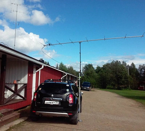
Recently, the domestic industry has begun to produce reconfigurable AVK for digital, see Fig. The idea, I must say, is excellent: by moving the elements along the boom, you can fine-tune the antenna to local reception conditions. It is better, of course, for a specialist to do this - the element-by-element adjustment of the AVC is interdependent, and an amateur will certainly get confused.

About “Poles” and amplifiers
Many users have Polish antennas, which previously received analogue decently, but refuse to accept digital - they break or even disappear completely. The reason, I beg your pardon, is the obscene commercial approach to electrodynamics. Sometimes I feel ashamed for my colleagues who have concocted such a “miracle”: the frequency response and phase response resemble either a psoriasis hedgehog or a horse’s comb with broken teeth.
The only good thing about the Poles is their antenna amplifiers. Actually, they do not allow these products to die ingloriously. Belt amplifiers are, firstly, low-noise, broadband. And, more importantly, with a high-impedance input. This allows, at the same strength of the EMF signal on the air, to supply several times more power to the tuner input, which makes it possible for the electronics to “rip out” a number from very ugly noise. In addition, due to the high input impedance, the Polish amplifier is an ideal USS for any antennas: whatever you attach to the input, the output is exactly 75 Ohms without reflection or creep.
However, with a very poor signal, outside the zone of reliable reception, the Polish amplifier no longer works. Power is supplied to it via a cable, and power decoupling takes away 2-3 dB of the signal-to-noise ratio, which may not be enough for the digital signal to go right into the outback. Here you need a good TV signal amplifier with separate power supply. It will most likely be located near the tuner, and the control system for the antenna, if required, will have to be made separately.

The circuit of such an amplifier, which has shown almost 100% repeatability even when implemented by novice radio amateurs, is shown in Fig. Gain adjustment – potentiometer P1. The decoupling chokes L3 and L4 are standard purchased ones. Coils L1 and L2 are made according to the dimensions in the wiring diagram on the right. They are part of signal bandpass filters, so small deviations in their inductance are not critical.
However, the installation topology (configuration) must be observed exactly! And just as required metal screen(metal shield), separating the output circuits from the other circuit.
Where to begin?
We hope that experienced craftsmen will find some useful information in this article. And for beginners who don’t yet feel the air, it’s best to start with a beer antenna. The author of the article, by no means an amateur in this field, was quite surprised at one time: the simplest “pub” with ferrite matching, as it turned out, takes the MV no worse than the proven “slingshot”. And what it costs to do both - see the text.
(2
ratings, average: 4,00
out of 5)
And on the roof there was a satisfactory reception for Polyachka. I’m 70–80 kilometers from the television center. These are the problems I have. From the balcony you can catch 3-4 pieces from 30 channels, and then with “cubes”. Sometimes I watch TV channels from the Internet on the computer in my room, but my wife cannot watch her favorite channels normally on her TV. Neighbors advise installing cable, but you have to pay for it every month, and I already pay for the Internet, and my pension is not flexible. We keep pulling and pulling and there’s not enough for everything.
Pyotr Kopitonenko said:
It’s not possible to install an antenna on the roof of the house; the neighbors swear that I walk around and break the roofing material covering and then their ceiling leaks. Actually, I am very “grateful” to that economist who received a prize for saving money. He came up with the idea of removing the expensive gable roof from the houses and replacing it with a flat roof covered with poor roofing material. The economist received money for saving, and the people on the top floors now suffer all their lives. Water flows on their heads and on their beds. They change the roofing felt every year, but it becomes unusable within a season. In frosty weather, it cracks and rainwater and snow flow into the apartment, even if no one walks on the roof!!!
Sergey said:
Greetings!
Thanks for the article, who is the author (I don’t see the signature)?
The LPA works perfectly according to the above method, UHF channels 30 and 58. Tested in the city (reflected signal) and outside the city, distances to the transmitter (1 kW) respectively: 2 and 12 km approximately. Practice has shown that there is no urgent need for the “B1” dipole, but another dipole before the shortest one has a significant effect, judging by the signal intensity in %. Especially in city conditions, where you need to catch (in my case) the reflected signal. Only I made an antenna with a “short circuit”, it turned out that way, there was simply no suitable insulator.
In general, I recommend it.
Vasily said:
IMHO: people looking for an antenna to receive digital TV, forget about the LPA. These wide-range antennas were created in the second half of the 50s (!!) of the last century in order to catch foreign television centers while on the shores of the Soviet Baltic states. In magazines of the time, this was bashfully called “extra-long-range reception.” Well, we really loved watching Swedish porn at night on the Riga seaside...
In terms of purpose, I can say the same about “double, triple, etc. squares”, as well as any “zigzags”.
Compared to those similar in range and gain " wave channel» LPAs are more bulky and material-intensive. Calculating the LPA is complex, intricate and more like fortune telling and adjusting the results.
If in your region ECTV is broadcast on neighboring UHF channels (I have 37-38), then the best solution is to find a book online: Kapchinsky L.M. Television antennas (2nd edition, 1979) and make a “wave channel” for a group of UHF channels (if you broadcast above 21-41 channels, you will have to recalculate) described on page 67 et seq. (Fig. 39, Table 11).
If the transmitter is 15 - 30 km away, the antenna can be simplified by making it four - five element, simply without installing directors D, E and Zh.
For very close transmitters, I recommend indoor antennas; by the way, in the same book on pp. 106 – 109 there are drawings of wide-range indoor “wave channel” and LPA. The “wave channel” is visually smaller, simpler and sleeker with higher gain!
By clicking the “Add comment” button, I agree with the site.
Digital terrestrial television (DVB-Digital Video Broadcasting) is a technology for transmitting television images and sound using digital encoding of video and sound. Digital coding, unlike analogue, ensures signal delivery with minimal losses, since the signal is not affected by external interference. At the time of writing, 20 digital channels are available, and this number should increase in the future. This number of digital channels is not available in all regions; you can find out more precisely about the possibility of receiving digital channels on the website www.rtrs.rf. If your region has digital channels, then you just need to make sure that your TV supports DVB-T2 technology (this can be found in the documentation for the TV) or purchase a DVB-T2 set-top box and connect the antenna. The question arises - Which antenna should I use for digital television? or How to make an antenna for digital television? In this article I would like to dwell in more detail on antennas for watching digital television, and in particular I will show how to make your own antenna for digital television.
The first thing I would like to emphasize is that digital television does not require a specialized antenna; an analog antenna (the one you used previously to watch analog channels) is quite suitable. Moreover, only a television cable can be used as an antenna...
In my opinion, the simplest antenna for digital television is a television cable. Everything is extremely simple, take a coaxial cable, put an F connector and an adapter for connecting to a TV on one end, and at the other end the central core of the cable is exposed (a kind of whip antenna). All that remains is to decide how many centimeters to expose the central core, since the quality of reception of digital channels depends on this. To do this, you need to understand at what frequency digital channels broadcast in your region, to do this, go to the website www.rtrs.rf/when/ here on the map, find the tower closest to you and see at what frequency digital channels broadcast.
You will receive more detailed information if you click the "More details" button.

Now we need to calculate the wavelength. The formula is very simple:
where, λ (lamda) is the wavelength,
c - speed of light (3-10 8 m/s)
F - frequency in hertz
or simpler λ=300/F (MHz)
In my case, the frequency is 602 MHz and 610 MHz, for the calculation I will use the frequency of 602 MHz
Total: 300/ 602 ≈ 0.5 m = 50 cm.
Leaving half a meter of the central core of a coaxial cable is not beautiful and inconvenient, so I will leave half, or maybe a quarter, of the wavelength.
l=λ*k/2
where l is the length of the antenna (central core)
λ - wavelength (calculated earlier)
k - shortening factor, since the length of the entire cable will not be large, this value can be considered equal to 1.
As a result, l=50/2=25 cm.
From these calculations it turned out that for a frequency of 602 MHz I need to expose 25 cm of coaxial cable.
Here is the result of the work done

This is what the antenna looks like when installed.

View of the antenna when watching TV.

Today, the DVB-T digital standard has been used for broadcasting television signals. To receive broadcasts on analog TVs, you can make an antenna for digital TV with your own hands, which is connected to a special set-top box that converts the signal.
[Hide]
Requirements for a digital packet television antenna
To ensure signal reception and transmission to the amplifier, the antenna must meet the following requirements:
- The collecting elements must be located along the axis of the waves coming from the transmitter.
- Have protection against interference with a frequency close to the television signal. Sources of interference can be other radio signals, interference from operating electric motors and generators.
- The antenna design should minimize signal power loss during transmission.
- The antenna circuit must be oriented according to the type of polarization.
Types of TV antennas
Antennas for receiving television signals are divided into several types, differing in the frequencies of the received signals.
The following types are widespread:
- An all-wave antenna that can receive digital and analog signals. The reception distance of analog signals is not large and does not exceed the line-of-sight range of a television tower.
- Log-periodic antenna capable of receiving meter and decimeter waves.
- A decimeter antenna designed to receive only short waves.
The author of the video, Dmitry, will talk about making a simple antenna for digital TV.
How to find out the initial data for calculating an antenna
The key parameter on which the quality of digital signal reception depends is the wavelength of the radiation. Based on this length, the overall dimensions of the antenna mustache are selected. To determine the wavelength, a calculation is used using the formula λ=300/F, where F is equal to the frequency of the transmitted signal in MHz. This parameter is publicly available and can be easily installed through any Internet search engine.
Made from a cardboard box
The simplest version of a home antenna, which you can quickly make yourself using available materials, is a device based on a cardboard shoe box.
For production you will need:
- food grade aluminum foil;
- a piece of standard coaxial cable;
- masking or stationery tape;
- a tube of quick-drying glue, for example, rubber “Moment”.
The manufacture of the antenna is as follows:
- Cut the foil to the shape of the bottom of the box. Lubricate the box with glue and stick the foil, smoothing it evenly along the bottom.
- Cut two pieces of coaxial cable 500 mm long.
- Remove the cable shielding insulation from each end to a distance of no more than 25 mm.
- Move the screen and twist it into a separate core.
- Bend each segment into a circle shape.
- Secure the sections on the outside of the box lid in the shape of a number 8 using tape. The ends of the cable should be directed towards the center of the figure eight and located at a distance of at least 10 mm from each other.
- At a length of about 100 mm, strip the outer insulation of the cable that will connect the antenna to the receiver.
- Twist the screen into a separate core.
- Gradually remove the insulation of the central conductor until a section of bare wire with a length of about 95-100 mm is obtained.
- Pierce the bottom of the box along with the foil and insert the cable inside.
- Lead the wire through the cover and run it along the contour of one of the parts of the “eight” to the central part. Secure the cable.
- Connect three braid strands together. Then fasten the three terminals of the central wire. Re-secure the knot with tape.
- Install the plug on the opposite end of the coaxial cable.
- Place the antenna in the place of best reception, which is determined experimentally.
If everything is done correctly, the antenna will allow you to receive the main television channels in DVB T2 format. The photo below shows the main stages of antenna manufacturing.
Covering the bottom with foil  Laying rings on the lid
  Main cable supply
  Connection of conductors
How to make an all-wave antenna
Those who want to save on purchases can make an antenna for receiving a digital signal themselves by choosing one of the designs described below.
From coaxial cable
The simplest antenna design can be considered a piece of coaxial cable 2-3 m long, which has a plug at one end. The free end is cleared of the outer layer of insulation, the screen is woven into a separate conductor and taken to the side. Then the insulation of the central wire is cut off in small pieces. After this, the wire is placed on a window or windowsill, selecting a suitable location experimentally.
It should be noted that this design is only effective at a range of reliable reception, where the singal is quite powerful. If you are far away from the repeater or the receiver is located in a densely built area, it is necessary to use other antenna designs.
Of two petals
This version of the TV antenna is made from a pair of small metal plates shaped like an isosceles triangle and two wooden or plastic slats. Copper wire with a diameter of 2-4 mm is stretched between these elements.
Lobe antenna circuit
The pitch of fastening the wire on the slats is 25-30 mm. The triangular bases are connected to each other by soldering at a distance of 10 mm from each other, the wire is also soldered to the triangles. To connect to the television receiver, a coaxial cable RK75 is used. The wire screen is connected to the rail (the place is indicated by a yellow dot), and the central wire is connected to the junction of the triangles. In areas of poor reception, it is recommended to use the antenna in conjunction with an amplifier.
Butterfly
For more stable reception of the terrestrial television signal, a “butterfly” antenna is used. A homemade device of a similar design can be used at home and in the country. It will provide good reception quality only with a stable broadcast signal.
To make a receiving device you will need materials and tools from the list:
- a board with a length of at least 600 mm and a width of about 70 mm, the thickness can be any, but preferably 15-20 mm;
- single-core copper wire with a conductor diameter of at least 4 mm;
- wood or metal screws and washers;
- coaxial cable RK75;
- plug connector for antenna;
- roulette;
- side cutters;
- Phillips screwdriver;
- wire stripper;
- soldering iron with a power of 40-60 W;
- solder and flux for soldering.
A do-it-yourself digital TV antenna is assembled as follows:
- Mark the board that will serve as the antenna frame in accordance with the schematic drawing below. The distance between the vertical rows of holes is 25 mm. The holes are located at the same distance from the edges of the board.
- Cut the wire into 8 pieces of 375 mm and two pieces of 220 mm.
- Remove approximately 25mm of insulation from the center of each long piece.
- Bend the cables into a V shape with equal lengths. The distance between the ends should be 75 mm.
- Install the V-shaped sections on the board using self-tapping screws. For tight fixation, washers should be placed under the heads of the screws.
- Before tightening the screws, install additional short connectors. On short wires it is necessary to remove the insulation at the points of contact with the V-shaped conductors.
- Connect the coaxial cable to the bottom row of screws. The installation diagram is shown below.
Can antenna with protective cover
How to make a log periodic antenna
To make the frame of such a device, the following are used:
- aluminum U-shaped profile with a side height of about 15 mm;
- studs with a suitable diameter and length or smooth tubes and rods are used as antenna whiskers;
- a small piece of aluminum tube with a diameter of 10-15 mm, which is used as a support.
The sequence of manufacturing a simple antenna is as follows:
- Flatten the tube at both ends and bend it into a U shape. One flattened end should be attached to the U-shaped profile using self-tapping screws.
- Make pairs of antenna whiskers with lengths of 70, 85, 100, 120, 140 and 170 mm. Cut a thread on one side.
- Drill holes in the U-shaped profile to install the mustache. The distances between the holes are indicated in the diagram.
- Screw a nut onto each whisker and install the assembled part into the hole of the U-shaped profile.
- Secure the mustache inside the profile using nuts. Place a connecting terminal under each nut, which can be factory-made or homemade from a copper conductor.
- Solder the mustache outputs in a certain sequence (shown in the diagram).
Ring antenna diagram: 1 - ring, 2 - additional loop, 3 - main cable
In the form of a frame
Another option is a frame structure called a Kharchenko antenna, made of thick copper wire with a diameter of 30-4 mm.
The antenna assembly looks like this:
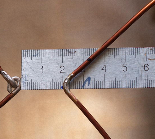
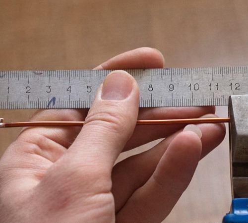
- Cut the wire 112 cm long.
- Strip and tin the ends of the wire that will be bent into loops.
- Bend it in the form of two rectangles in the following sequence - a fixation loop of 10 mm, then a rib 130 mm long, then two ribs of 140 mm, two of 130, two of 140, the last rib is 130 mm long and ends with a loop that The last 10 mm of wire goes away.
- Connect the loops at the ends and solder the joint.
- Move this angle apart from the opposite one by 20 mm (shown in the photo below). Tin the wire located opposite the joint of the loops.
- Strip the coaxial cable 20 mm for the screen and 10 mm for the central core.
- Solder the leads to the tinned corners on the frame.
- Make a central body from a plastic cap of a suitable size.
- Place the squares of the frame with the cable into the housing and fill it with hot glue. After the glue has hardened, install the antenna in the place of best signal reception.
To calculate the parameters of the Kharchenko antenna, there are specialized online calculators that calculate all the product data.
Amplifier based on the MAX2633 circuit
To make an amplifier, you will need three capacitors with a capacity of 1 nF and a resistance with a nominal value of 1 kOhm. To power such a device, a constant voltage of 3 to 5 V is used. The device does not require adjustment, but the degree of amplification is adjusted by setting a resistance of a different value (to reduce the degree of amplification, it is necessary to increase the resistance). Such an amplifier is not broadband and is applicable only for the shortwave range.
For broadband amplification when receiving signals over long distances, transistor devices are used, circuit diagrams which are given below.
 Amplifier based on the common emitter of the KT368 transistor
  Amplifier based on the common base of the KT315 transistor
  Two-transistor amplifier
In the process of self-assembly of such devices, it is necessary to produce printed circuit boards with tracks. When using wires to connect elements, the amount of interference increases, which will reduce the gain of the device.
For an amplifier based on KT368 you will need resistances and capacitors with the following parameters:
- 100 Ohm (R1 and R4);
- 470 Ohm (R2);
- 51 kOhm (R3);
- 1000 pF (C1);
- 33 pF (C2);
- 15 pF (C4 and C3).
The assembled amplifier is installed as close as possible to the receiver and can be used for any type of antenna. It requires no setup and runs on 9V DC power.
To expand the frequency range, amplifiers built on a common transistor base are used. These devices also do not require additional adjustment of operating parameters.
During the assembly process you will need the following components:
- 51 Ohm (R1);
- 10 kOhm (R2);
- 15 kOhm (R3);
- 1 kOhm (R4);
- The capacitors have the same rating as in a common emitter circuit.
The amplifier circuit uses a choke coil, which is wound from 300 turns of 0.1 mm wire (PEV type) on a ferrite ring.
In the case of a very weak signal, it is possible to use multi-stage circuits operating from direct current with a voltage of 12 V and built on two transistors of the GT311D type.
The amplifier circuit for long-range antennas uses:
- 680 Ohm (R1);
- 75 kOhm (R2);
- 1 kOhm (R3);
- 150 kOhm (R4);
- 100 pF (C1, C2, C4);
- 6800 pF (C3);
- 15 pF (C5);
- 3.3 pF (C6);
- 100 µH (L1);
- 25 µH (L2);
- homemade choke made of 25 turns of PEV2 wire with a diameter of 0.8 mm (L3).

The era of digital signals has arrived. All broadcast television companies began to work in a new format. Analog TVs are reaching their end. They are still in working order and are found in almost every family.
In order for older models to successfully complete their service life, and for people to be able to use them when watching digital broadcasting, it is enough to connect the DVB-T set-top box to the TV receiver and pick up the TV wave signals with a special antenna.
Any home craftsman can not buy an antenna in a store, but make it with his own hands from available materials for watching digital TV programs at home or in the country. The two most accessible designs are described in this article.
A little theory
Operating principle of an antenna for digital packet television
Any television signal propagates in space from the emitters of the transmitting television tower to the TV antenna by an electromagnetic wave of a sinusoidal shape with a high frequency, measured in megahertz.

When an electromagnetic wave passes through the surface of the receiving beams of the antenna, a voltage V is induced in it. Each half-wave of a sinusoid forms a potential difference with its own sign.
Under the influence of an induced voltage applied to a closed receiving circuit of the input signal with resistance R, an electric current flows in the latter. It is amplified and processed by the digital TV circuit and output to the screen and speakers as image and sound.

For analog models of TV receivers, an intermediate link works between the antenna and the TV - a DVB-T set-top box, which decodes digital information of an electromagnetic wave into a normal form.
Vertical and horizontal polarization of digital TV signal
In television broadcasting, state standards require electromagnetic waves to be emitted in only two planes:
- horizontal.

In this way, transmitters send emitting signals.
And users simply need to rotate the receiving antenna in the desired plane to maximize the power potential.
Requirements for a digital packet television antenna
TV transmitters distribute their signal waves to short distances, limited by the line of sight from the top point of the TV tower emitter. Their range rarely exceeds 60 km.
For such distances, it is enough to provide a small power of the emitted TV signal. But, the strength of the electromagnetic wave at the end of the coverage area should form a normal voltage level at the receiving end.
A small potential difference, measured in fractions of a volt, is induced at the antenna. It creates currents with small amplitudes. This imposes high technical requirements on the installation and quality of manufacturing of all parts of digital reception devices.
The antenna design should be:
- manufactured carefully, with a good degree of accuracy, eliminating loss of electrical signal power;
- directed strictly along the axis of the electromagnetic wave coming from the transmitting center;
- oriented according to the type of polarization;
- protected from extraneous interference signals of the same frequency coming from any sources: generators, radio transmitters, electric motors and other similar devices.
How to find out the initial data for calculating an antenna
The main parameter influencing the quality of the received digital signal, as can be seen from the explanatory first figure, is the length of the electromagnetic wave of radiation. Under it, symmetrical arms of vibrators of various shapes are created, and the overall dimensions of the antenna are determined.
The wavelength λ in centimeters can be easily calculated using a simplified formula: λ=300/F. It is enough just to find the frequency of the received signal F in megahertz.
To do this, we will use a Google search and ask it for a list of regional TV communication points for our area.
As an example, a fragment of a data table for the Vitebsk region is shown with the transmitting center in Ushachi highlighted in red.

Its wave frequency is 626 megahertz, and its polarization type is horizontal. This data is quite sufficient.
We carry out the calculation: 300/626=0.48 m. This is the length of the electromagnetic wave for the antenna being created.
We divide it in half and get 24 cm - the desired half-wave length.
The tension reaches its maximum value in the middle of this section - 12 cm. It is also called amplitude. The whip antenna is made to this size. It is usually expressed by the formula λ/4, where λ is the electromagnetic wavelength.
The simplest TV antenna for digital television
It will require a piece of coaxial cable with a characteristic impedance of 75 Ohms and a plug for connecting the antenna. I managed to find a ready-made two-meter piece in the old stock.

I cut off the outer shell from the free end with a regular knife. I take the length with a small margin: when setting up it is always easier to bite off a small piece.

Then I remove the shielding layer from this section of the cable.


The work is done. All that remains is to insert the plug socket into the connector on the TV signal set-top box and direct the bare wire of the inner core across the incoming electromagnetic wave, taking into account horizontal polarization.

The antenna should be placed directly on the window sill or secured to the glass, for example, with a piece of tape, or tied to the blind mount. Reflected signals and interference can be shielded with a strip of foil located a short distance from the central core.
Such a design can be done in literally ten minutes and does not require any special material costs. It's worth trying. But, it is capable of working in an area of reliable signal reception. My building is screened by a mountain and a multi-story building. The transmitting television tower is located at a distance of 25 km. Under these conditions, the digital electromagnetic wave is reflected many times and is poorly received. I had to look for another technical solution.
And for you on the topic of this design, I suggest you watch the video by the owner of Edokoff “How to make an antenna for digital TV”
Kharchenko antenna at 626 MHz
To receive analogue television signals of various wave frequencies, the design of a zigzag broadband antenna, which does not require complex manufacturing, worked well for me before.
I immediately remembered one of their effective varieties - the Kharchenko antenna. I decided to use its design for digital reception. I made the vibrators from a flat copper bar, but it’s quite possible to get by with round wire. This will make it easier to bend and straighten the ends.

How to determine the dimensions of a specific antenna
Online calculator
Let's use the all-knowing Google search. We write to command line: “Calculation of the Kharchenko antenna” and press Enter.

We choose any site you like and perform online calculations. I went into the first one that opened. This is what he calculated for me.

I presented all his data with a picture indicating the size of the Kharchenko antenna.

Manufacturing of antenna design parts
I took the information provided as a basis, but did not accurately maintain all the dimensions. I know from previous practice that the antenna works well in the broadband wavelength range. Therefore, the dimensions of the parts were simply slightly increased. The half-wave of each harmonic of the sine wave of the electromagnetic TV signal will fit into the arm of each vibrator and will be received by it.
Based on the selected data, I made blanks for the antenna.

Vibrator design features
The connection of the ends of the figure eight busbar is created in the center at the bending stage. I soldered them with a soldering iron.

I created it according to the “Moment” principle, made it with my own hands from old transformers, and has been working for two decades. I even soldered 2.5 square copper wire with it in thirty-degree frost. Works with transistors and microcircuits without burning them out.
In the near future I plan to describe its design in a separate article on the website for those who also want to make it themselves. Follow publications, subscribe to notifications.
Connecting the antenna cable to the vibrator
I simply soldered the copper core and braid to the metal of the figure eight from different sides in its center.

The cable was tied to a copper bar, bent into a loop in the shape of a semi-square vibrator. This method matches the resistance of the cable and antenna.
Screening grid design
In fact, the Kharchenko antenna often works normally without signal shielding, but I decided to show its manufacture. For the base I took a wooden block. I did not paint or varnish: the structure will be used indoors.
In the back side of the block I drilled holes for attaching the screen wires and inserted them, and then wedged them.

The result was a screen for the Kharchenko antenna. In principle, it can be made of a different design: cut from a piece of frontal armor of a tank or cut from food foil - it will work approximately the same.

On the back side of the bar I secured the vibrator structure with a cable.

The antenna is ready. All that remains is to install it on a window to work in vertical polarization.

When a television receiver is located at a great distance from the transmitting generator, the power of its signal gradually weakens. It can be increased by special electronic devices - amplifiers.
You just need to clearly see the difference between the signals received by the antenna, which can be:
- simply weakened;
- contain high-frequency interference that distorts the shape of the digital sinusoid into the shape of some kind of “doodleball”.
In both cases, the amplifier will fulfill its role and increase the power. Moreover, the TV will clearly perceive and display a weakened signal, but with an amplified signal, playback problems will arise.
The waves are designed to eliminate such interference:
- high-pressure filters;
- screens.
They must be measured with an oscilloscope, and the methods of using various designs must be analyzed individually in each specific case. The antenna is not to blame here.