Working with a 16x2 display on the HD44780 controller in Bascom-AVR
LCD displays on the HD44780 controller (as well as the compatible KS0066) are very common due to the simple method of working with them, as well as their low price. Depending on the design of the display, they allow you to display from 8 to 40 characters in each line; there can be one, two or four lines. The most common are 8*2 (eight characters*two lines), 16*2 and 20*4.
For example, let's look at the pinout of the 16*2 indicator (it is similar for all displays on the HD44780 controller)
Each display on the HD44780 controller has 14 pins for connection + 2 pins for backlighting (if available):
- Ground, GND
- Supply voltage, Vcc (+5V)
- Contrast adjustment, Vo
- Register select, R/S
- Read/Write, R/W
- Read/Write Enable Signal, E
- Bit 0, D0
- Bit 1, D1
- Bit 2, D2
- Bit 3, D3
- Bit 4, D4
- Bit 5, D5
- Bit 6, D6
- Bit 7, D7
- Backlight power supply for backlit displays, LED+
- Backlight supply for backlit displays, LED -
Data is loaded into the display via the data bus (D0-D7), while the controller supports both 8- and 4-bit connections. A 4-bit connection saves microcontroller legs and is most often sufficient for many tasks (with an 8-bit connection you can load data into the display controller faster, but we don’t need this for now, so we won’t consider it). For a 4-bit connection, the last 4 bits of the bus (D4-D7) are used.
As an example, we will use a 20x4 display connected to the ATmega8 microcontroller via a 4-bit interface according to the diagram below

The display requires 5 volts for power, the divider on resistor R1 adjusts the contrast of the displayed characters, the R/W pin is connected to ground (i.e., permanent recording to the display is selected). You can connect the remaining pins to any free legs of the microcontroller. The configuration of the legs for connecting the display of the ATmega8 microcontroller will look like this:
$regfile
= "m8def.dat"
$crystal
=
1000000
"operating frequency 1 MHz
Config
Lcd=
20
*
4
Config
Lcdpin = Pin, Db4 = PortB. 3, Db5 = PortB. 2, Db6 = PortB. 1, Db7 = PortB. 0, E = PortB. 4, Rs = PortB.5
CLS - cleaning the display
LCD - display data ( example: LCD "Hello world" will display the inscription Hello world )
Now let’s write this small program that will display the inscription on the display:
$regfile
= "m8def.dat" "selected microcontroller type
$crystal
=
1000000
"operating frequency 1 MHz
Config
Lcd=
20
*
4
"we indicate what kind of display we have
"and configure the legs for connection
Config
Cursor
Off
Cls
"let's clear the display
Lcd
"LCD 20*4 HD44780"
Locate
2
,
8
"move the cursor to the second line, eighth familiarity
Lcd
"site" "display text
End
As a result, the display will show the following:

Bascom-AVR also has several additional commands for working with displays:
HOME- also returns the cursor to the top line, but unlike the UPPERLINE command, this command can take additional values: if you put a letter after it L, T or F then the cursor will move to the beginning of the line whose name begins with the corresponding letter (example: in order to move the cursor to the beginning of the third line, you need to write the command HOME
T
)
Example code for displaying information using these commands:
$regfile
= "m8def.dat" "selected microcontroller type
$crystal
=
1000000
"operating frequency 1 MHz
Config
Lcd=
20
*
4
"we indicate what kind of display we have
"and configure the legs for connection
Config
Lcdpin = Pin, Db4 = Portb. 3, Db5 = Portb. 2, Db6 = Portb. 1, Db7 = Portb. 0, E = Portb. 4, Rs = Portb. 5
Cursor
Off"turn off the cursor display
Cls
"let's clear the display
Lcd
"*** HD44780 LCD ***" "print the text in the first line
Lowerline
"go to the second line
Lcd
"Line number 2" "we display the text
Thirdline
"go to the third line
Lcd
"AaBbCcDdEeFfGgHfIiJj" "we print on the third line
Fourthline
"go to the fourth line
Lcd
"1234567890"
"print on the fourth line
End
"end of program

and an example of how to use text shift:
$regfile
= "m8def.dat" "selected microcontroller type
$crystal
=
1000000
"operating frequency 1 MHz
Dim
A AsByte"variable for loop organization
Config
Lcd=
20
*
4
"we indicate what kind of display we have
"and configure the legs for connection
Config
Lcdpin = Pin, Db4 = Portb. 3, Db5 = Portb. 2, Db6 = Portb. 1, Db7 = Portb. 0, E = Portb. 4, Rs = Portb. 5
Cursor
Off"turn off the cursor display
Cls
"let's clear the display
Locate
1
,
11
"set the cursor on the first line, the tenth familiarity
Lcd
"Bascom-AVR" "will display the text
"shift left loop
For
A=1 To 10
"we repeat this cycle until variable A reaches the value 10
ShiftlcdLeft"move the text to the left
Waitms 300
"delay 300 milliseconds
Next
A
"shift right loop
For
A=1 To 10
"we repeat the loop until variable A reaches the value 10
ShiftlcdRight"now let's move the text to the right
Waitms 300
"delay 300 milliseconds
Next
A "increase the value of variable A by 1
"continue executing the program
Wait
1
"delay 1 second
Home
F "place the cursor on the bottom line
Lcd
"END PROGRAM" "and display the inscription
End
"end of program
To work with character graphic displays, we suggest using the LiquidCrystal library, which is included in the standard Arduino IDE set and is designed to work via an 8-bit (4-bit) parallel interface. If your display is connected to the Arduino via the I2 bus, then you need to install the LiquidCrystal_I2C library (most of the functions of which repeat the functions of the first library).
Supported displays:
| Display | Connection and initialization |
|---|---|
LCD1602 - character display (16x02 characters), 
|
#include [ , 8 , 9 , 10 , 11 ]); void setup())( lcd.begin(16 , 2);} // Explanation:
|
with I2C interface (blue) 
|
#include #include LiquidCrystal_I2C lcd(0x27 or 0x3F, 16 , 2); void setup())( lcd.init(); } // Explanation: |
| LCD1602 I2C - character display (16x02 characters), with I2C interface (green) 
|
#include #include LiquidCrystal_I2C lcd(0x27 or 0x3F, 16 , 2); void setup())( lcd.init(); } // Explanation: |
| LCD2004 - character display (20x04 characters), with parallel interface (blue) 
|
#include LiquidCrystal lcd(2 , 3 , 4 , 5 , 6 , 7[ , 8 , 9 , 10 , 11 ]); void setup())( lcd.begin(20 , 4);} // Explanation:
// If 8 data bus wires are used, then indicate them all |
| LCD2004 I2C - character display (20x04 characters), with I2C interface (blue) |
#include #include LiquidCrystal_I2C lcd(0x27 or 0x3F, 20 , 4); void setup())( lcd.init(); } // Explanation: |


#1 Example
We display the inscription on the LCD1602 display connected via the I2C bus. To work with the LCD2004 display, you need to change line 3 to LiquidCrystal_I2C lcd(0x27,20,4);
#include
#2 Example
We display the inscription on the LCD1602 display connected via a 4-bit parallel bus. To work with the LCD2004 display, you need to change line 5 to lcd.begin(20, 4);
#include
#3 Example
We display the inscription “Russian language” on the LCD1602 display connected via the I2C bus:
#include
Functions common to the LiquidCrystal and LiquidCrystal_I2C libraries:
- begin( cols, rows, ); – Initializes the display with the number of columns, rows and character size.
- clear();– Clearing the display with the cursor at position 0,0 (Takes a lot of time!).
- home();– Setting the cursor to position 0,0 (Takes a lot of time!).
- display();– Quickly turn on the display (without changing the data in RAM).
- noDisplay();– Quickly turn off the display (without changing the data in RAM).
- blink();– Turn on the blinking cursor (with a frequency of about 1 Hz).
- noBlink();– Turn off the flashing cursor.
- cursor();– Enable cursor underlining.
- noCursor();– Disable cursor underlining.
- scrollDisplayLeft();– Scrolls the display to the left. Shifts display coordinates one column to the left (without changing RAM).
- scrollDisplayRight();– Scrolls the display to the right. Shifts display coordinates one column to the right (without changing RAM).
- leftToRight();– Specifies to further shift the cursor position, after displaying the next character, one column to the right.
- rightToLeft();– Specifies to further shift the cursor position, after displaying the next character, one column to the left.
- noAutoscroll();– Specifies that text will be aligned to the left of the cursor position in the future (as usual).
- autoscroll();– Indicates that the text will be aligned to the right from the cursor position in the future.
- createChar( num,array ); – Write a custom character to the display CGRAM under the specified number.
- setCursor( col,row ); – Place the cursor at the position indicated by the column and line number.
- print( text ); – Display text, symbols or numbers on the display screen. The syntax is similar to the Serial class function of the same name.
Functions implemented only in the LiquidCrystal_I2C library:
- init();– Display initialization. Must be the first LiquidCrystal_I2C library command after object creation. In fact, this function is also in the LiquidCrystal library, but in that library it is called automatically (by default) when an object is created.
- backlight();– Turn on the display backlight.
- noBacklight();– Switches off the display backlight.
- setBacklight( flag ); – Backlight control (true - turn on / false - turn off), used instead of the noBacklight and backlight functions.
Connection:
|
// For I2C bus: |
Parameter:
|
| // For a 4-wire parallel bus: #include LiquidCrystal lcd( R.S. , E , D4 , D5 , D6 , D7 ); void setup())( lcd.begin( col , row ); } |
Parameter:
|
| // For an 8-wire parallel bus: #include LiquidCrystal lcd( R.S. , E , D0 , D1 , D2 , D3 , D4 , D5 , D6 , D7 ); void setup())( lcd.begin( col , row ); } |
|
| begin( col ,
row ,
);
Initializes the display with screen dimensions and characters. |
Parameter:
|
Display control functions:
| display(); Turns on the display after it has been turned off by the noDisplay function. |
Note: The function runs quickly and does not change the display RAM. |
| noDisplay(); Turns off the display. The data on the display will not be displayed until the display function is called, but it will not be erased from the RAM memory, and after the display function is called, it will be displayed again. |
Note: The function runs quickly and does not change the display RAM. |
| scrollDisplayLeft(); Shifts the display coordinates one column to the left. |
|
| scrollDisplayRight(); Shifts the display coordinates one column to the right. Constantly calling this function will create a creeping line effect. The coordinates are shifted both for the information available on the display and for that which will be displayed later. |
Note: The function works without changing the display RAM. If you call the function 40 times in a row, the coordinate will return to the original point |
| clear(); Clears the display by setting the cursor to position 0,0. The information on the display will be permanently erased. |
Note: Takes a long time. |
| backlight(); Turn on the display backlight. |
|
| noBacklight(); Turn off the display backlight. |
Note: The function is implemented only in the LiquidCrystal_I2C library. |
| setBacklight( flag );
Backlight control (instead of the noBacklight and backlight functions). |
Parameter:
|
Cursor control functions:
| setCursor( col ,
row );
Places the cursor at the specified position. |
Parameter:
|
| home(); Setting the cursor to position 0,0. Works like the function setCursor(0,0); |
Note: Takes a long time. |
| blink(); Enable blinking cursor. |
Note: The cursor occupies the entire character field and blinks at a frequency of about 1 Hz, in the position where it was previously set. |
| noBlink(); Turn off the blinking cursor. |
Note: The cursor becomes invisible, but its position is maintained. |
| cursor(); Enable cursor underlining. |
Note: The cursor takes the form of an underscore character and is located in the position where it was previously placed. |
| noCursor(); Turn off cursor underlining. |
Note: The cursor becomes invisible, but its position is maintained. |
Functions indicating direction and alignment:
| leftToRight(); Specifies that after each new character, the cursor position should move one column to the right. |
Note: If you display the text "abc" the display will show "abc" and the text will be to the right of the original cursor position. (As usual) |
| rightToLeft(); Specifies that after each new character, the cursor position should move one column to the left. |
Note: If you display the text "abc" the display will display "cba" and the text will be to the left of the original cursor position. (Writing from right to left) |
| noAutoscroll(); Indicates that in the future, text should be aligned to the left of the original cursor position. |
Note: if you place the cursor at position 10.0 and display text, then the first character of the displayed text will be at this position. (As usual) |
| autoscroll(); Indicates that in the future, text should be aligned to the right of the original cursor position. |
Note: if you place the cursor at position 10.0 and display text, the cursor will be at this position. (The display coordinates will be shifted to the left, as if you called the scrollDisplayLeft function as many times as there are letters in the output text) |
Text and symbol input functions:
| createChar(num,array); Writes a custom character to the display's CGRAM under the specified number. If you want to display text (using the print function) that should contain the character you set, specify a slash and the number under which this character was written: print("C\1MBO\2"). |
Parameter:
|
| print(text); Display text, symbols or numbers on the display screen. |
Parameter:
|
At the request of the workers, and also my promises, I decided to describe the work with the iconic 16x2 LCD in the CodeVisionAVR environment. Let's start with a description of the LCD itself. The alphanumeric LCD display with built-in Hitachi HD44780 chip can display characters in one, two or four terms of 8, 16, 20 or 40 characters each. In this article I will consider LCD 16x2 (16 characters, 2 lines). This display for physical connection to the MK has 16 pins (the location of the pins depends on the manufacturer). Let's look at these findings. Without further ado, I stole the sign in MELT. In principle, it is suitable for any LCD.  Well, I think there is no need to explain why this or that pin is needed. Everything is written there in Russian. But there are a few small but. 1) LCD displays can be produced in two versions: 5 volts or 3.3. 2) A current-limiting resistor is not always installed in the power circuit. Look carefully, there may just be a jumper. (I burned out the backlight on two displays this way.) 3) Circuit for connecting a resistor to adjust the contrast.
  So, well, now how to connect this miracle to the MK. We will work with ATmega8 and quartz at 4 MHz. Here is the actual diagram.
  As you can see, there is nothing complicated. The first three digits of the port D serve for control, and the last four for data. It is also possible to work with these displays on an 8-bit bus, but I think giving away an extra 4 legs is a waste. Therefore, we will work on a 4-bit bus. We've figured out the circuit, now let's look at the software part. To initialize the display and switch it to 4-bit mode, you need to run several commands. But before that, I want to explain how control bits work. The RS bit is responsible for what the LCD will receive. If RS = 0, then we send the command, and if 1
then data. If bit RW=0, then we write to the LCD, and if 1
, then we read. Bit E just a strobe. That is, as soon as we want to enter a command or data, then after we have set all the bits on the legs we simply set them to 1
bit E, and then we drop it again 0
. 1 - Turn on the power 2 - Pause for at least 20 ms 3 - Command for 4 bits. bus 4 - Maintain a pause of at least 40 µs 5 - Command for 4 bits. tires (RS=0), (RW=0), (D7=0), (D6=0), (D5=1), (D4=1) 6 - Maintain a pause of at least 40 µs 7 - Command for 4 bits. tires (RS=0), (RW=0), (D7=0), (D6=0), (D5=1), (D4=1) 8 - Maintain a pause of at least 40 µs 9 - Command for 4 bits. tires (RS=0), (RW=0), (D7=0), (D6=0), (D5=1), (D4=0) 10 - Maintain a pause of at least 40 µs 11 - Set parameters (RS=0), (RW=0), (D7=0), (D6=0), (D5=1),(D4=0) (RS=0), (RW=0), (D7= 1), (D6=0), (D5=0), (D4=0) 12 - Turn off the display (RS=0), (RW=0), (D7=0), (D6=0), (D5=0),(D4=0) (RS=0), (RW=0), (D7= 0), (D6=0), (D5=1), (D4=0) 13 - Clear the screen (RS=0), (RW=0), (D7=0), (D6=0), (D5=0),(D4=0) (RS=0), (RW=0), (D7= 0), (D6=0), (D5=0),(D4=1) 14 - Data input mode (RS=0), (RW=0), (D7=0), (D6=0), (D5=0),(D4=0) (RS=0), (RW=0), (D7= 0), (D6=1), (D5=1),(D4=0) Oh how. Now after this gobbledygook our display is ready to receive data. What's next. And then let's look at the LCD commands. To transmit commands/data to the LCD via a 4-bit bus, two passes are required. We transmit the most significant 4 bytes first, and the lowest 4 bytes are transmitted second. From now on I will write all the commands in pairs. The command to clear the indicator and place the cursor in the upper left corner. RS=0, RW=0, D4=0, D5=0, D6=0, D7=0 (E=1 then 0) RS=0, RW=0, D4=0, D5=0, D6=0, D7=1 (E=1 then 0) Command to move the cursor to the left position. (X means who cares what the value is)
RS=0, RW=0, D4=0, D5=0, D6=0, D7=0 (E=1 then 0) RS=0, RW=0, D4=0, D5=0, D6=1, D7=X (E=1 then 0) The command sets the direction of cursor shift (ID=0/1 left/right). Also display shift resolution (SH=1) when writing to DDRAM. RS=0, RW=0, D4=0, D5=0, D6=0, D7=0 (E=1 then 0) RS=0, RW=0, D4=0, D5=1, D6=ID, D7=SH (E=1 then 0) Command to turn on the display (D=1) and select the cursor (A, B). A=0, B=0 There is no cursor, nothing blinks A=0, B=1 There is no cursor, the entire symbol blinks A=1, B=0 Cursor in the form of an underline, does not blink A=1, B=1 Cursor appears as an underline and blinks RS=0, RW=0, D4=0, D5=0, D6=0, D7=0 (E=1 then 0) RS=0, RW=0, D4=1, D5=D, D6=A, D7=B (E=1 then 0) Display/cursor shift command (SC=0/1 cursor/display RL=0/1 left/right). RS=0, RW=0, D4=0, D5=0, D6=0, D7=1 (E=1 then 0) RS=0, RW=0, D4=SC, D5=RL, D6=X, D7=X (E=1 then 0) Command for setting the bus width (DL=0/1 4/8 bits) As well as character generator pages P. RS=0, RW=0, D4=0, D5=0, D6=1, D7=DL (E=1 then 0) RS=0, RW=0, D4=1, D5=0, D6=P, D7=0 (E=1 then 0) The command for setting the address of the next operation with placing the cursor there and selecting the CGRAM area (Your own invented characters). RS=0, RW=0, D4=0, D5=1, D6=ACG, D7=ACG (E=1 then 0) RS=0, RW=0, D4=ACG, D5=ACG, D6=ACG, D7=ACG (E=1 then 0) Command for setting the address of the subsequent operation and selecting the DDRAM memory area (Character Generator). RS=0, RW=0, D4=0, D5=1, D6=ADD, D7=ADD (E=1 then 0) RS=0, RW=0, D4=ADD, D5=ADD, D6=ADD, D7=ADD (E=1 then 0) Command Write data to the current area. RS=1, RW=0, D4=DATA, D5=DATA, D6=DATA, D7=DATA (E=1 then 0) RS=1, RW=0, D4=DATA, D5=DATA, D6=DATA, D7=DATA (E=1 then 0) Command Read data into the current area. RS=1, RW=1, D4=DATA, D5=DATA, D6=DATA, D7=DATA (E=1 then 0) RS=1, RW=1, D4=DATA, D5=DATA, D6=DATA, D7=DATA (E=1 then 0) That's actually all the commands. There is also a command to read the busy flag, but I don’t use it, I just wait at least 40 µs between each command. That's all. Now, after reading this treatise, drink a cup of tea or coffee and forget about all this. Since all this crap is taken over by functions from the CodeVisionAVR library. We create a new project as already described. For those who are not in the know, go here, the rest go to the tab in the code generator LCD and choose PORTD.
As you can see, there is nothing complicated. The first three digits of the port D serve for control, and the last four for data. It is also possible to work with these displays on an 8-bit bus, but I think giving away an extra 4 legs is a waste. Therefore, we will work on a 4-bit bus. We've figured out the circuit, now let's look at the software part. To initialize the display and switch it to 4-bit mode, you need to run several commands. But before that, I want to explain how control bits work. The RS bit is responsible for what the LCD will receive. If RS = 0, then we send the command, and if 1
then data. If bit RW=0, then we write to the LCD, and if 1
, then we read. Bit E just a strobe. That is, as soon as we want to enter a command or data, then after we have set all the bits on the legs we simply set them to 1
bit E, and then we drop it again 0
. 1 - Turn on the power 2 - Pause for at least 20 ms 3 - Command for 4 bits. bus 4 - Maintain a pause of at least 40 µs 5 - Command for 4 bits. tires (RS=0), (RW=0), (D7=0), (D6=0), (D5=1), (D4=1) 6 - Maintain a pause of at least 40 µs 7 - Command for 4 bits. tires (RS=0), (RW=0), (D7=0), (D6=0), (D5=1), (D4=1) 8 - Maintain a pause of at least 40 µs 9 - Command for 4 bits. tires (RS=0), (RW=0), (D7=0), (D6=0), (D5=1), (D4=0) 10 - Maintain a pause of at least 40 µs 11 - Set parameters (RS=0), (RW=0), (D7=0), (D6=0), (D5=1),(D4=0) (RS=0), (RW=0), (D7= 1), (D6=0), (D5=0), (D4=0) 12 - Turn off the display (RS=0), (RW=0), (D7=0), (D6=0), (D5=0),(D4=0) (RS=0), (RW=0), (D7= 0), (D6=0), (D5=1), (D4=0) 13 - Clear the screen (RS=0), (RW=0), (D7=0), (D6=0), (D5=0),(D4=0) (RS=0), (RW=0), (D7= 0), (D6=0), (D5=0),(D4=1) 14 - Data input mode (RS=0), (RW=0), (D7=0), (D6=0), (D5=0),(D4=0) (RS=0), (RW=0), (D7= 0), (D6=1), (D5=1),(D4=0) Oh how. Now after this gobbledygook our display is ready to receive data. What's next. And then let's look at the LCD commands. To transmit commands/data to the LCD via a 4-bit bus, two passes are required. We transmit the most significant 4 bytes first, and the lowest 4 bytes are transmitted second. From now on I will write all the commands in pairs. The command to clear the indicator and place the cursor in the upper left corner. RS=0, RW=0, D4=0, D5=0, D6=0, D7=0 (E=1 then 0) RS=0, RW=0, D4=0, D5=0, D6=0, D7=1 (E=1 then 0) Command to move the cursor to the left position. (X means who cares what the value is)
RS=0, RW=0, D4=0, D5=0, D6=0, D7=0 (E=1 then 0) RS=0, RW=0, D4=0, D5=0, D6=1, D7=X (E=1 then 0) The command sets the direction of cursor shift (ID=0/1 left/right). Also display shift resolution (SH=1) when writing to DDRAM. RS=0, RW=0, D4=0, D5=0, D6=0, D7=0 (E=1 then 0) RS=0, RW=0, D4=0, D5=1, D6=ID, D7=SH (E=1 then 0) Command to turn on the display (D=1) and select the cursor (A, B). A=0, B=0 There is no cursor, nothing blinks A=0, B=1 There is no cursor, the entire symbol blinks A=1, B=0 Cursor in the form of an underline, does not blink A=1, B=1 Cursor appears as an underline and blinks RS=0, RW=0, D4=0, D5=0, D6=0, D7=0 (E=1 then 0) RS=0, RW=0, D4=1, D5=D, D6=A, D7=B (E=1 then 0) Display/cursor shift command (SC=0/1 cursor/display RL=0/1 left/right). RS=0, RW=0, D4=0, D5=0, D6=0, D7=1 (E=1 then 0) RS=0, RW=0, D4=SC, D5=RL, D6=X, D7=X (E=1 then 0) Command for setting the bus width (DL=0/1 4/8 bits) As well as character generator pages P. RS=0, RW=0, D4=0, D5=0, D6=1, D7=DL (E=1 then 0) RS=0, RW=0, D4=1, D5=0, D6=P, D7=0 (E=1 then 0) The command for setting the address of the next operation with placing the cursor there and selecting the CGRAM area (Your own invented characters). RS=0, RW=0, D4=0, D5=1, D6=ACG, D7=ACG (E=1 then 0) RS=0, RW=0, D4=ACG, D5=ACG, D6=ACG, D7=ACG (E=1 then 0) Command for setting the address of the subsequent operation and selecting the DDRAM memory area (Character Generator). RS=0, RW=0, D4=0, D5=1, D6=ADD, D7=ADD (E=1 then 0) RS=0, RW=0, D4=ADD, D5=ADD, D6=ADD, D7=ADD (E=1 then 0) Command Write data to the current area. RS=1, RW=0, D4=DATA, D5=DATA, D6=DATA, D7=DATA (E=1 then 0) RS=1, RW=0, D4=DATA, D5=DATA, D6=DATA, D7=DATA (E=1 then 0) Command Read data into the current area. RS=1, RW=1, D4=DATA, D5=DATA, D6=DATA, D7=DATA (E=1 then 0) RS=1, RW=1, D4=DATA, D5=DATA, D6=DATA, D7=DATA (E=1 then 0) That's actually all the commands. There is also a command to read the busy flag, but I don’t use it, I just wait at least 40 µs between each command. That's all. Now, after reading this treatise, drink a cup of tea or coffee and forget about all this. Since all this crap is taken over by functions from the CodeVisionAVR library. We create a new project as already described. For those who are not in the know, go here, the rest go to the tab in the code generator LCD and choose PORTD.
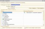
 What did we do with it? First, we told the program that we wanted to work with the LCD display (by selecting the tab LCD). Then we said that we would connect it to the port D. The drop-down list below allows you to select the number of characters per line. Since the default is 16
, and we want to work with a 16x2 LCD, then we don’t need to change anything. Below, as a hint, the port legs for correctly connecting the LCD to the MK are painted. That's it, save the project and look at the newly generated code. The first thing you need to pay attention to is the piece of code after the preprocessor directive #include
What did we do with it? First, we told the program that we wanted to work with the LCD display (by selecting the tab LCD). Then we said that we would connect it to the port D. The drop-down list below allows you to select the number of characters per line. Since the default is 16
, and we want to work with a 16x2 LCD, then we don’t need to change anything. Below, as a hint, the port legs for correctly connecting the LCD to the MK are painted. That's it, save the project and look at the newly generated code. The first thing you need to pay attention to is the piece of code after the preprocessor directive #include  Next function. void lcd_puts(char *str) This function prints a string located in SRAM starting from the current position. Example: lcd_gotoxy(0,0); lcd_puts("ROW"); We see:
  Next function. void lcd_putsf(char *str) This function prints the string located in FLASH starting from the current position. Example: lcd_gotoxy(0,0); lcd_putsf("ROW"); We see: Well, the “Eraser” function brings this whole mess to a close. void lcd_clesr(void) By calling this function, you will erase everything that is on the display, and the cursor will move to the far left position of the top line. This is how, to begin with, you can display words and numbers on the LCD display using ready-made functions. Now let's talk about how to display the value of variables. For these purposes we will need another library. Well, those who programmed in C on a PC should know about it. It's called stdio.h We rise to the very top of the program and after the preprocessor directive #include
  So we learned how to display formatted text on the LCD. Next, I’ll briefly go over the types of transformation. i d- To output a signed decimal integer u- To output unsigned decimal integer e -d.d e-d
E- To display real floating point data -d.d E-d
f- To display real floating point data -d.d
x- For output in hexadecimal in small letters X- For output in hexadecimal in capital letters c- For output to symbol If you write %-05d then the sign "-"
will force alignment to the left, and blanks will not be filled with zeros. If you try to print a floating point number, you will be very surprised. The number will not be printed. It's an ambush)) The problem lies in the compiler settings. In order for the compiler to begin to understand the format float you need to tweak it a little. For this we go Project->Configure and go to the tab C Compiler. In property (s)printf Features: choose float, width, precision. That's all. Try it, experiment. If you have any questions, write on the forum. Good luck!
So we learned how to display formatted text on the LCD. Next, I’ll briefly go over the types of transformation. i d- To output a signed decimal integer u- To output unsigned decimal integer e -d.d e-d
E- To display real floating point data -d.d E-d
f- To display real floating point data -d.d
x- For output in hexadecimal in small letters X- For output in hexadecimal in capital letters c- For output to symbol If you write %-05d then the sign "-"
will force alignment to the left, and blanks will not be filled with zeros. If you try to print a floating point number, you will be very surprised. The number will not be printed. It's an ambush)) The problem lies in the compiler settings. In order for the compiler to begin to understand the format float you need to tweak it a little. For this we go Project->Configure and go to the tab C Compiler. In property (s)printf Features: choose float, width, precision. That's all. Try it, experiment. If you have any questions, write on the forum. Good luck!
- The FC-113 module is based on the PCF8574T chip, which is an 8-bit shift register - an input-output “expander” for the I2C serial bus. In the figure, the microcircuit is designated DD1.
- R1 is a trim resistor for adjusting the contrast of the LCD display.
- Jumper J1 is used to turn on the display backlight.
- Pins 1…16 are used to connect the module to the LCD display pins.
- Contact pads A1...A3 are needed to change the I2C address of the device. By soldering the appropriate jumpers, you can change the device address. The table shows the correspondence of addresses and jumpers: “0” corresponds to an open circuit, “1” to an installed jumper. By default, all 3 jumpers are open and the device address 0x27.
2 Connection diagram for LCD display to Arduino via I2C protocol
The module is connected to Arduino in a standard way for the I2C bus: the SDA pin of the module is connected to analog port A4, the SCL pin is connected to analog port A5 of Arduino. The module is powered by +5 V from Arduino. The module itself is connected by pins 1…16 to the corresponding pins 1…16 on the LCD display.

3 Library for work via I2C protocol
Now we need a library to work with LCD via the I2C interface. You can use, for example, this one (link in the line "Download Sample code and library"). 
Downloaded archive LiquidCrystal_I2Cv1-1.rar unzip to a folder \libraries\, which is located in the Arduino IDE directory.
The library supports a set of standard functions for LCD screens:
| Function | Purpose |
|---|---|
| LiquidCrystal() | creates a LiquidCrystal type variable and accepts display connection parameters (pin numbers); |
| begin() | initializing the LCD display, setting parameters (number of lines and characters); |
| clear() | clearing the screen and returning the cursor to the starting position; |
| home() | return the cursor to the starting position; |
| setCursor() | setting the cursor to a given position; |
| write() | displays the symbol on the LCD screen; |
| print() | displays text on the LCD screen; |
| cursor() | shows the cursor, i.e. underlining under the place of the next character; |
| noCursor() | hides the cursor; |
| blink() | cursor blinking; |
| noBlink() | Cancel flashing; |
| noDisplay() | turning off the display while saving all displayed information; |
| display() | turning on the display while saving all displayed information; |
| scrollDisplayLeft() | scroll the display contents 1 position to the left; |
| scrollDisplayRight() | scroll the display contents 1 position to the right; |
| autoscroll() | enable autoscroll; |
| noAutoscroll() | disable autoscroll; |
| leftToRight() | sets the text direction from left to right; |
| rightToLeft() | text direction from right to left; |
| createChar() | creates a custom character for the LCD screen. |
4 Sketch for text output to LCD screen via I2C bus
Let's open the sample: File Samples LiquidCrystal_I2C CustomChars and we'll change it up a little. We will display a message at the end of which there will be a blinking symbol. The comments to the code comment on all the nuances of the sketch.
#include
By the way, the characters written by the command lcd.createChar();, remain in the display memory even after turning off the power, because written to display ROM 1602.
5 Create your own symbols for LCD display
Let's take a closer look at the issue of creating your own symbols for LCD screens. Each character on the screen consists of 35 dots: 5 wide and 7 high (+1 reserve line for underlining). In line 6 of the above sketch we define an array of 7 numbers: (0x0, 0xa, 0x1f, 0x1f, 0xe, 0x4, 0x0). Convert hexadecimal numbers to binary: {00000, 01010, 11111, 11111, 01110, 00100, 00000} . These numbers are nothing more than bit masks for each of the 7 lines of the symbol, where "0" denotes a light point and "1" a dark point. For example, a heart symbol specified as a bitmask will appear on the screen as shown in the figure.

6 LCD screen control via I2C bus
Let's upload the sketch to Arduino. The inscription we specified with a blinking cursor at the end will appear on the screen.

7 What's behind I2C bus
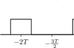
As a bonus, let's look at the timing diagram for displaying the Latin characters "A", "B" and "C" on the LCD display. These characters are stored in the display ROM and are displayed on the screen simply by transmitting their addresses to the display. The diagram is taken from the RS, RW, E, D4, D5, D6 and D7 pins of the display, i.e. already after the FC-113 “I2C parallel bus” converter. We can say that we are diving a little deeper into the hardware.
 Timing diagram of the output of Latin characters “A”, “B” and “C” on the LCD display 1602
 The diagram shows that the characters that are in the display ROM (see p. 11 of the datasheet, link below) are transmitted in two nibbles, the first of which determines the table column number, and the second - the row number. In this case, the data is “latched” at the edge of the signal on the line E(Enable), and the line R.S.(Register select) is in a logical one state, which means data is being transferred. A low state on the RS line means instructions are being sent, which is what we see before each character is transmitted. In this case, the instruction code for carriage return to position (0, 0) of the LCD display is transmitted, which can also be found out by studying the technical description of the display.
And one more example. This timing diagram shows the output of the Heart symbol on the LCD display.

Again, the first two impulses Enable comply with instructions Home()(0000 0010 2) - return the carriage to position (0; 0), and the second two - output to the LCD display stored in memory cell 3 10 (0000 0011 2) the “Heart” symbol (instruction lcd.createChar(3, heart); sketch).
Reader of our blog Mikhail ( mishadesh) created an excellent library for working with LCD and suggested writing an article to demonstrate its capabilities. Actually, this is exactly what we will be talking about today 😉 Let’s look at what functions are implemented, and at the end of the article there will be an example for working with the display.
As usual, let's start with a discussion of hardware... But there’s really nothing to talk about. As in the first article on working with displays (), we will use a development board Mini STM32. Actually, connecting the display, the basic commands for recording data, the sequence of instructions for initialization - it’s all there =) Therefore, now let’s go straight to discussing the library for working with graphic displays.
Here is a complete list of functions with explanations:
The next function, as its name suggests, changes the screen orientation. Two screen positions are possible, respectively, two possible parameter values orientation:
- Orientation_Portrait
- Orientation_Album
The function draws a symbol on the graphic display, positioning it according to the coordinates passed to the function, and also setting its color. The character style matches the font defined in the file font.c(the file is included in the library).
From function LCD_DrawChar() The following function flows smoothly:
| void LCD_DrawString(char * s, uint16_t x, uint16_t y, uint16_t color, uint16_t backColor, uint8_t isTransparent) ; |
It’s clear here without further ado 😉 The function prints on LCD line of text. The basis for this function is the previous one - LCD_DrawChar().
In addition to symbols and text, of course, you need to be able to draw basic graphic primitives, such as a line or a circle. To do this, the following has been implemented:
| void LCD_drawLine (int x1, int y1, int x2, int y2, uint16_t color) ; void LCD_DrawRect ( int x1, int y1, int x2, int y2, uint16_t color, uint8_t filled ) ; void LCD_DrawEllipse(uint16_t X1, uint16_t Y1, uint16_t R, uint16_t color) ; |
To draw a line, you need to pass the coordinates of the starting point, the coordinates of the end point, and the desired color to the function. For a rectangle - the coordinates of the upper left corner and the coordinates of the lower right corner (!). Last parameter filled– determines whether the shape should be filled. One means yes, the figure will be painted with the selected color, zero means only the outline of the figure will be drawn. This is clear) All that remains is the circle - the function DrawEllipse(). Here, instead of the coordinates of the start and end (upper/lower corners), we pass the center of the circle and the radius as arguments.
And finally, one more function:
| void LCD_FillScr(uint16_t color) ; |
The function allows you to fill the screen with a solid color.
All listed functions are implemented in the file GUI_DRV.c.
In addition to them, the library includes functions for writing data to the display ( LCD_DRIVER.c) as well as the already mentioned fonts ( font.c). As you can see, everything is clearly sorted into different files, so in principle everything is very clear, so let's move on to a practical example!
Let's find out! Let's go to the file main.c... I will not give the complete code for the functions for initializing the peripherals and display; all this can be viewed directly in the file, or in the previous article, the link to which was at the beginning of this article 😉 Function main():
| int main(void ) ( initPeriph() ; initFSMC() ; initLCD() ; delay(10000 ) ; LCD_FillScr(0xFFFF ) ; delay(100 ) ; LCD_SetOrient(Orientation_Album) ; delay(100 ) ; LCD_DrawString( "Library for LGDP4532", 30 , 30 , 0x888F , 0x0000 , 0 ) ; LCD_DrawRect(100, 100, 200, 200, 0x0000, 0); LCD_DrawRect(120, 120, 180, 180, 0xFF00, 1); LCD_DrawEllipse(150, 150, 50, 0xF000); while (1 ) ( ) ) |
We start with initialization, paint the screen white and set the screen orientation to landscape. And now we move on to drawing graphics)
We display a line on the screen, as well as two rectangles and a circle. The result is clear:

Obviously everything works great 😉
So, that’s where we end for today, many thanks to Mikhail for the work done and the materials provided. Here are the contacts of the library author:
Skype - mishadesh
Mail – [email protected]
That's all, thank you for your attention, see you soon!