Didn't know how to set up or optimize the radar in CS GO? In this thread, we are just going to take a look at the radar settings in CS Global Offensive.What is needed to set up a radar? Everything is done very simply, you do not need to download any additional software, all you need is:
Turn on the console
If you have problems opening the console, then follow the instructions below:
- Launch CS: GO;
- Settings → Game Settings;
- Enable developer console -\u003e Yes;
- Settings → Keyboard / Mouse;
- Scroll to the bottom and see "Open Console" turns on " ` "- you can set any of your keys.
Now you can start setting up!
Radar setup
The first thing that I would advise you is to create a game with bots so that they cannot kill you and, already in the game, deal with setting up the radar. Let's start:
Enabling / disabling radar
To turn on radar, you must write the drawradar command in the console;
To hide radar use the hideradar console command;
cl_hud_radar_scale
This command is responsible for the size of the radar on your screen.
 |
|
| cl_hud_radar_scale "0.8" | cl_hud_radar_scale "1.3" |
| Minimum: "0.8" // Maximum: "1.3" | |
cl_radar_always_centered
The player is always in the center of the radar. At first glance, it may seem that there is not much difference, but the plus is obvious - when you are in the corner of the map, you have a greater view of the terrain on the radar than if you were in the center of the radar.
 |
 |
| cl_radar_always_centered "0" | cl_radar_always_centered "1" |
| Two variables are available for selection either 0 or 1 | |
cl_radar_icon_scale_min
This command resizes the various icons on your radar.
| cl_radar_icon_scale_min "0.4" | cl_radar_icon_scale_min "1.0" |
| Minimum: "0.4" // Maximum: "1.0" | |
cl_radar_rotate
Turns the radar rotation on and off. Those. if disabled, the map on the radar will always be in the same position.
 |
 |
| cl_radar_rotate "0" | cl_radar_rotate "1" |
| Can be set to either 0 or 1 | |
cl_radar_scale
Change the scale of the map displayed on the radar.
 |
 |
| cl_radar_scale "0.25" | cl_radar_scale "1.0" |
| Minimum: "0.25" // Maximum: "1.0" | |
cl_hud_bomb_under_radar
This command enables or disables the display of the bomb icon when you are carrying it, or when you do not have it.
Dynamically resizing the radar
There are times when the map scale on the radar needs to be increased or vice versa, decreased. This can be done using the bind below:
Bind "KP_plus" "incrementvar cl_radar_scale 0.25 1.0 0.05"; // increase the size of the radar bind "KP_minus" "incrementvar cl_radar_scale 0.25 1.0 -0.05"; // reduce the size of the radar
This bind allows the button + or - dynamically resize the radar when you press. The buttons can be any at your discretion.
Standard radar settings
cl_hud_radar_scale "1"; cl_radar_always_centered "1"; cl_radar_icon_scale_min "0.6"; cl_radar_rotate "1"; cl_radar_scale "0.7"; cl_hud_bomb_under_radar "1";Reading 5 min. Views 3.9k.
Traffic on modern roads is monitored by electronic traffic police radar devices - video cameras that identify traffic offenders from the entire traffic flow. European countries have long been accustomed to the fact that the car traffic is constantly monitored.
In Russia, the practice of controlling traffic with cameras is only at the stage of development, but it is already meeting resistance from the "craftsmen" who use jammers from cameras. An industrial product with such properties is called an active radar detector.
Purpose
An active antiradar (jammer) is a device that, due to the emission of a strong signal, distorts and suppresses the scanning signals of the radar. The frequency at which the active anti-radar works is prohibited for use by individuals.
Radar detectors can be of 2 types; their design and principle of operation mainly depend on the detector, which can jam the signal in the radio or laser range. It should be borne in mind that laser anti-radars cannot suppress radio signals.
Principle of operation
Active radar works on the principle of aggressive action on the signal source. Such devices are prohibited by law in many countries. The principle of operation is that the detector picks up the radar signal, instantly processes it and sends it back. The signal strength is such that the data on the vehicle speed is lost, and accordingly, it becomes impossible to determine it.
Wide spectrum laser diodes are used as detectors of laser radars. To exclude false alarms, the entire system must be adjusted to emit signals of a given frequency, power and wavelength. The high-quality operation of the device depends on the number of sensors in the radar detector, given that 1 is able to scan the radar at a distance provided that its beam hits the sensor.

Hence the conclusion: the more sensors the radar has, the higher the probability of suppressing the signal of the traffic police device. The same one working on radio frequencies that jam the signals of police radars.
Which model to choose
Antiradars from popular manufacturers located on the Russian market of car accessories can be conditionally divided into the following categories in terms of functionality and cost: budget, medium price segment and premium.
When choosing a radar, it is necessary to take into account the device parameters that will be most demanded by the driver:
- Protection against interference and the number of false positives.
- Reliability level.
- Accuracy of recorded signals.
- Speed.
- Signal reception range.
- Great functionality.
When choosing a budget category radar, they are guided not so much by the functionality of the device as by its cost, which in this case is the main factor:
- ParkCity RD-11. A device leading in this category. Work in a narrow frequency range. Unreliable protection against interference.
- Prestige RD-101. Good fixation of signals, voice notification with low quality of the display.
- Silver Stone F1 Fuji. Good signal fixation. It works both in the radar-detector mode and the active radar detector. Poor volume control for distance.
Antiradars of the middle price category are chosen taking into account the price / quality ratio and functionality:
- Sho Me G-1000 Signature. A modern device with a laser receiver. Reliable operation and protection against false alarms.
- Playme QVICK 2. The device is manufactured using anti-CAS technology. Reliable with good anti-jamming capability.
- Inspector RD GTS. Signature device with GPS and laser receiver. Reliable signal clamping and interference protection.
Premium category antiradars are considered not only for availability functionality, but also from the point of view of devices that have no room for error:
- Whistler Pro-80ST RU. A modern, multifunctional, compact radar that meets all the requirements of drivers. Reliable, with good signal retention and anti-jamming.
- Neoline X-COP S300. Multifunctional antiradar, consisting of 3 units located under the hood and dashboard. Reliable fixation of all signals, excellent protection against interference.
- Playme SILENT, which is also called "jammer from radar cameras", is highly efficient. Reliable with excellent anti-jamming capability. A real radar detector is equipped with an OLED display and is expensive.
How to do it yourself
In order to make a radar detector with your own hands, you need to know how the radar works, which consists of 3 parts. It is a transmitter that emits a directional radio signal to the vehicle, which bounces back after being reflected from the vehicle. The second part of the device is a receiver that receives the reflected radio signal from the car. The third component of the radar calculates the speed of the vehicle from the speed of the reflected radio signal.

The anti-radar function is to receive the signal of the radar installation and timely warn the driver with the signal. This function of the signaling device can be performed by any screwdriver with a sound indicator, designed for work with hidden electrical wiring, which can be found in the household department of any store, and it is inexpensive.
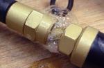
The antiradar manufacturing scheme is simple. To do this, connect the metal part of the screwdriver with a wire to the car antenna, and connect the ground to the screwdriver contact switch.
You can check such a device on the go: if on the road a homemade radar detector starts to squeak, warning the driver, then there is a police post with a radar installation in front. Reviews of motorists who have checked this device in their practice say that the device works, but sometimes there is not enough distance to change the speed of movement.
What the law says
In many countries of the world, the use of even radar detectors when operating vehicles is prohibited, not to mention active radars. Jammers are not licensed as radio transmission media and fall under the administrative clause. Penalties for individuals using an active radar range from 500 to 1000 rubles. with the removal of these devices.
In practice, there has not yet been any cases of finding jammers in a car and subsequent proof of their use. finding them is extremely difficult. In addition, traffic police officers know little about them. Laser devices do not fall under the administrative clause, because are not radio transmitting devices.
ANTI-RADAR SCHEME
Probably every driver at least once had an idea to acquireantiradar, especially after the next racket of the traffic police on the road. So get down to business! But let's clarify right away:antiradar is an overwhelming devicepolice radar, and assembling it is a very difficult task. Here we will consider a simpler anti-radar scheme - the so-calledradar - a detector that signals that an inspector is scanning your car.
To measure the speed of a car, the traffic police radar receives radiation reflected from the car, and the radar detector - direct, so the radar detector is always able to detect the radar earlier than it measures the speed of the car! So, if a traffic cop scans from his radar 500 m away from the car, this is the range of the Vizir device, then before the car approaches a visible distance of 100 m you have the opportunity to slow down.
This anti-radar circuit is quite common on the net, and although I personally did not collect it, I had to fix such a homemade device. There, a microwave diode - the detector stood in a small funnel made of tin and the whole structure fit into a body soldered from foil PCB, the size of a pack of cigarettes. Under microwave irradiation, it blinked and peaked. Here is another version of the anti-radar circuit from the magazineRadio:

All radars in service with the traffic police operate at frequencies of 10525 MHz, 24150 MHz and 34700 MHz. These radar detectors are capable of detecting all of them.
Customization antiradar circuits can be performed while standing near a person with a radar;

Or so as not to light up, near the stationary radar - camera:

Sometimes they are placed a couple of kilometers in front of the traffic police post:

Recently, the authorities have adopted: The VIZIR radar video recording speed meter consists of two independent units - a speed meter and a digital photo and video camera. The camera turns on both automatically when the driving car exceeds the pre-set speed limit, and manually - by an auto inspector. Surveillance cameras with built-in radar. The device works constantly, and when the speed is exceeded, a sensor is activated, which activates the camera.
The idea of \u200b\u200bcreating some kind of radar for determining the distance came to one of my students. We continued to develop it and decided to introduce it into the course program as one of the projects.
After a couple of weeks of preparation, we finally figured out how to start it and what we might need to do. The project didn't have to be very advanced; we set the difficulty level to medium. Below is an example of using personal narrow range radar. He was supposed to look a little funny, so you can laugh!
Description and purpose of the project
The goal of the project was to create a functioning radar. The system only needs to measure the distance at an angle of 90 degrees, as shown in the example above. Depending on the selected sensor, the system operates within 4-30 cm, 20-150 cm and 1-5.5 m.
The results of the project will influence subsequent developments in which we will try to integrate radar for the navigation of mobile robots in vivo.
Electronic parts
- Voltage stabilizer LM7805 5 V
- Microcontroller PIC18F452
- IR Sensor GP2D120
- Quartz resonator at 4 or 8 MHz
- Switch
- Capacitor
- 30-pin connector
- 5 triggers 74LS373
- Bread board
- Solder
- 36 indicators
- Wire 30 AWG
- Wire tools
- Soldering iron
Detailed list of spare parts
You may or may not know all about the above details, so a picture of every detail has been included to help clarify them. There are three new objects that were not previously specified in the project: a servo system and IR sensors. Description of IR sensors will appear soon; as for the 74HCT373, a brief overview will be presented below. You can always check the chip spec by simply searching for "74HCT373".

An eight-bit microcircuit containing a three-stable trigger. Simply put, this chip is capable of storing 8 bits of digital logic and holding it in memory until it is erased or changed through the LE-Latch Enable pin.
Work principles
- Control pins LE and OE
- 8 Data input D0-D7
- 8 Data output D0-D7
Power (Vcc & GND.)
Output activation (OE) allows Q0-Q7 to output data currently in the D flip-flops.
Trigger activation (LE) allows data contained in D0-D7 to be overwritten into the D-flip-flop.
Schema overview
The scheme for this project is much more complicated than the previous ones. There are 4 main advantages in our development.
- We will be able to program images from the developed board.
- We will control the servo system.
- We will be taking data from the IR distance sensor.
- We will install 36 LEB indicators to display the data output from the IR sensor.
Circuit characteristics
Food
- Power is supplied via a 9V battery connected to the LM7805 with a 1uF capacitor connected to pin / ground to provide uninterrupted DC current to the LM7805.
- Program cycle
- Programming is done by connecting two connectors from the controller to the programmer, giving the first connector on the programmer access to the MCLR * / Vpp-Pin1 on the controller. For safety reasons, a rectifier diode is installed.
- IR Distance Sensor
- The IR Sensor uses one controller connector PIN 2 - RA0. The analog capabilities of this pin are used to obtain the ADC value, since only the analog signal is taken from the IR sensor. This value tells you if there is something in the sensor's range.
LED indication
There are a total of 40 LED indicators. Each 74HCT373 chip controls up to 8 indicators; since 40/8 \u003d 5, we need 5 74HCT373 circuits to drive all 40 indicators. It should be noted in the diagram that one data bus is used for all 5 chips.
Theory
This development uses three main instruments to create a personal radar. The IR sensor is connected to the microcontroller, and then displayed on the indicator segment. A visual demonstration of this process is provided:
Using different sensors
An important aspect of the accuracy of the IR sensors used in this project is that they have the same voltage characteristics, so this program is compatible with all indicators. The only thing you need to know is how the sensor is used to determine the distance displayed on the indicators.
Using
So, let's take a look at the final look of the device:

Such is appearance assembled device. Let's move on to the next section and continue assembling the device.
The plastic case at the bottom of the picture was not mentioned in the parts list. This is a common housing that can be purchased from any electronics manufacturer or retailer. First of all, you need to drill 36 holes for the indicators in the circuit and fix the indicators in them. A fixing agent was used before inserting the indicators into the holes.

After the panel is soldered, we start connecting the circuit. Each wire must be connected through a small hole in the case.

The figure above shows an early view of the panel. At the beginning of connecting the wires, a huge amount of them accumulates, for example, like this:


The final touch in the development of a personal radar is the ability to use it online. The wires are 2-4 meters long when connecting the servo system and the IR sensor. We make a hole in the front of the case for these wires:
Having finished with the assembly, let's move on to the software part of the development. This is, by far, a more subtle part of development than even routing the wires.
The software for this instrument consists of three main parts:
- Servo control
- LED indication control
- input A / D /
Since all of the software for this project will not fit on one page, it will be explained what these parts are and how they work.
Servo control
The servo system is controlled by timers and interrupts. Two separate interrupts, triggered simultaneously to create the desired sound, generate a 50 GHz signal and the servo pointer moves in small steps to adjust the creaking sound.
Regulation of LED indication.
The indicators are controlled by the 74LS373 / 74HCT373 triggers. The system constantly updates the trigger data displayed on the indicators.
A / C Input
The IR sensor provides analog output. A converter is used to determine the voltage value, indicating that the object has moved beyond the range of the IR sensor.

The assembly and configuration of the device is completed - you need to test it. Depending on the sensor you are using, the indication will be different. Selectable sensors GP2D120, GP2Y0A21YK and GP2Y0A700K0F.
Data and observations
The first test of the radar will be a close range test. Tin cans were used as obstacles.
On the second video (on the first page), indicators of 20 cm - 150 cm and 1 m - 5.5 m are tested, allowing to overcome more serious obstacles. Take a look to see what this is about.
Two videos will show how the sensor works, but when self-assembly slight difficulties are possible, which will be described in the conclusion.
ABOUT personal radar overview
It takes a little time to assemble and configure this device. This is a project that you can do in a day, and it already has a niche in application, but over time, additional difficulties will arise. IR sensors can become unreliable and output results can be small due to environmental and environmental influences.
Actions to be taken
To increase the sensor's coverage radius, it is planned to use ultrasonic sensors, equivalent to the above-described "sound sensors", transmitting data on the distance from you to the object. Ultrasound has a wider range than infrared and is more reliable in harsh environments.
Conclusion
The project was an exciting exploration of infrared sensors. It demonstrates that results can be realistically obtained and used. Many further projects can be developed based on this.
Having the skills to work with microcontrollers, the radar can be made independently using microcircuits, a set of wires, an infrared sensor and other devices. You also need to have a diagram for further assembly.
You will need
- - skills in working with radio engineering and microcontrollers.