The circuit is working, the engraver has started. I even tried to burn something on dark cardboard.
As a first modification, I attached a 40x40x10 fan to the engraver body using a piece of 20x20x1.5mm corner to blow the laser and remove smoke from the engraving area.

Forum participant orensnake suggested trying the T2Laser program. I tried.

The program is excellent. I haven't come across anything more convenient yet. Several evenings of experimentation and I managed to burn the picture onto cardboard with halftones in acceptable quality. Controlled the laser power.

I'll still work on the program.
I found a 12V 2a power supply in a stash and decided to use it for the engraver. I bought and secured the connector for the power supply on the engraver, this is the second minor modification.

As a third and purely aesthetic modification, I drew and printed the caps in a 20x20 profile.


When I was researching the issue of building a laser engraver, I came across the Chinese program MyLarser - this is the program that comes with NeJe engravers.

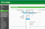
The first attempt to launch the engraver in this program did not work. A little later I read that the program works with the engraver at a speed of 9600 kbit/s. Firmware 1.1f works on 115200.
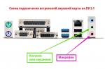
Since this engraver does not use end switches, and I soldered the board for a larger engraver project, I decided to solder another brain. Not difficult. Fortunately, there was one more Arduino and a number of breadboards in stock. As a 12-5V stabilizer I used a commonplace 7805 in a TO220 package. A plus on the board is a connector for a 12V fan.


I found on the Internet an old firmware 0.8c, running at a speed of 9600. I spilled it into the Arduino. Set it up.
Grbl 0.8c ["$" for help]
$0=106.667 (x, step/mm)
$1=106.667 (y, step/mm)
$2=106.667 (z, step/mm)
$3=10 (step pulse, usec)
$4=250.000 (default feed, mm/min)
$5=500.000 (default seek, mm/min)
$6=192 (step port invert mask, int:11000000)
$7=25 (step idle delay, msec)
$8=10.000 (acceleration, mm/sec^2)
$10=0.100 (arc, mm/segment)
$11=25 (n-arc correction, int)
$13=0 (report inches, bool)
$14=1 (auto start, bool)
$15=0 (invert step enable, bool)
$16=0 (hard limits, bool)
$17=0 (homing cycle, bool)
$18=0 (homing dir invert mask, int:00000000)
$19=25.000 (homing feed, mm/min)
$20=250.000 (homing seek, mm/min)
$21=100 (homing debounce, msec)
In addition to the difference in firmware settings, there is one more difference. In firmware 0.8, the output for laser control is port 12 (and in 0.9j and later, the 11th pin with PWM). The laser has only 2 states, on and off. No PWM regulation!
On the board I soldered the contacts for the jumper and connected them to ports 11 and 12. Now, by rearranging the jumper, the laser can be connected to port 11 or 12 of the Arduino.
The engraver installed this firmware using the MyLarser program. The program is extremely simple; the program comes with a set of pictures. Setting comes down to determining the engraving area and engraving time.
I managed to engrave the following pictures:


Of course, this homemade product is nothing more than a toy. However, this is a small step towards making a larger engraver in the future and with a normal, more powerful purchased laser.
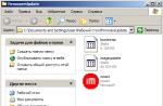
Most of the articles on the site describe working in the ArtCAM v8/v9 program. If you are using later versions of the program (v11/v12 or later), for the convenience of working with the program and articles, you must configure the layout after starting ArtCAM, as shown in the figure:
The file preparation is designed for a blue laser with a power of 1..10 W with a beam diameter of 0.25 mm.
A black and white dotted drawing in .bmp format prepared in a graphic program convenient for you is opened in the ArtCam program
File - Open

If necessary, scale (resize) the model.

In the ArtCam program, you need to change the model resolution - increase it approximately twice. Model ->Change resolution.

Use the slider in the left area to set the new resolution (1). The new resolution parameters should be approximately twice as large as the current resolution parameters. Next, click the Apply button (2).

Call the Form Editor. Model -> Form Editor or simply double-click the left mouse button on the black square at the bottom of the image (1). In the window that appears, select the FLAT button (2). Next, enter a value of 1 mm for the Initial height (3). Next - Subtract (4), Apply (5), Close (6).

A relief will appear in the 3D view area.

We create a LASER tool based on an end mill. For this
Go to the UE tab (1),
Select TOOL DATABASE (2),
Add a new tool (3),
Enter the name of the tool, select the type of tool - END, units of measurement mm/sec (4),
We set the diameter to 0.001, the processing depth is minimal (5),
Step - 0.001, speed, spindle - any (6),
Save the changes (7), save the creation of a new tool (8).

Staying in the NC tab (1), select RELIEF PROCESSING (2).

We adjust the trajectory of movement - SNAKE IN X, angle - 0, allowance - 0, accuracy - 0.001 (1).
Safety height in Z - 1, return point in X and Y - 0, in Z - 1 (2).
Tool Select (3) laser 0.001 (4),Select (5).

We indicate a step of 0.25 mm (laser focus) (1), depth per pass of 1 mm (2)

Determine the material (1), height of the workpiece 1.0 (2), pay attention to the offset (3), OK (4), give a name to the workpiece (5), calculate now (6), close (7).


Move the UE to the saved section (1),
Select G-Code (mm) (2),
Save (3),
Select the storage folder (4) and set the file name (5),
Save the changes (6) and close the window (7).

Next, you need to open the program program in Notepad and replace (Edit - Replace) all values of Z 1.000 with Z 0.010. If necessary, change the speed value to the required F1000. This is done so that the Z axis does not waste time, and the head moves at a constant speed without stopping or delaying turning the laser on/off.

Photo of a picture obtained by burning on a tabletop milling machine with a laser installed.

ATTENTION! When working with a laser, follow safety precautions. ALWAYS use glasses!
Burning from a photograph on an engraving and milling machine Modelist3040

Video of burning on a desktop milling machine Modelist3040
Video of laser paper cutting on the Modelit3040 machine

Engraver Master is a program that is designed to prepare burning patterns on a laser cutter. Using this free software, you can complete all stages of preparing an image for further application to wood or other material. EM is quite easy to use and offers a good set of functions, but if you are looking for an even more intuitive solution, we recommend paying attention to the program.
Usage
So, at the beginning of work on the project, the user will be asked to select the size of the workpiece. Next, you will need to upload a drawing (all popular graphic formats are supported), select its style and make minor external changes, then position the workpiece and send it for “burning”. In this case, the standard laser cutter parameters will be used. In order to change them, you can refer to the special section.
Engraver Master makes it possible to control the speed and depth of cutting, supports the burning mode for black dots, and also allows you to specify the step size of the laser power in individual areas. As for compatibility, Engraver Master works with almost any engraver model. You just have to download the drivers to connect them to your computer yourself from the manufacturer’s official website.
Additional functions
Among the interesting features of the program, it is worth highlighting the pause and continuation of “burning”, as well as convenient tools for setting up the workspace. If necessary, it allows you to work with several devices connected via a COM port at once.
By default, Engraver Master does not provide localization. But if necessary, it can be translated into Russian using an amateur Russifier, which, by the way, is made of very high quality.
Key Features
- preparing images and diagrams for burning on a laser cutter;
- control of the basic parameters of “burning”;
- convenient positioning and adjustment of the work area;
- support for burning mode on black areas;
- nice interface in Russian.
Programs for a CNC laser machine are software that allows you to create sketches of future products and turn virtual models into real samples.
Using a laser machine, you can cut products and blanks of various levels of complexity from solid materials. However, in order for the machine to “understand” what exactly it needs to do, two types of software are required: graphic editors for modeling and programs for controlling the machine itself and all cutting processes.
Modeling
Laser equipment works with flat objects, so for computer modeling of future products, programs such as:
- CorelDraw- a software package that deservedly has a lot of fans. It features an interface that is understandable even for amateurs, a large number of tools and templates, and works with vector and raster images. Saves images in many formats, including the .cdr format, which is necessary for the further creation of G-code that is understandable to the laser machine.
- Adobe Illustrator- an equally popular professional graphic editor that is perfect for creating sketches for laser cutting. Works with vector graphics, has a rich library of ready-made sketches, templates, fonts, styles, symbols, etc.
- LibreCAD- younger and therefore less widely known software for drawing and 2D design. A simple interface with a minimum of settings, .dxf support, a “step back” function, many options and tools - these characteristics are quite enough to create computer models for laser cutting.
Of course, you can create sketches in programs that work with 3D models, so if the user is familiar only with SolidWorks, he does not need to learn CorelDraw to work with a laser machine. All well-known software packages for 3D design (SolidWorks, AutoCAD, ArtCAM, MasterCAM, 3ds Max, KOMPAS-3D, etc.) are suitable for working with flat shapes, but you need to be prepared for the fact that the model will have to be adjusted - often when When exporting a volumetric model to a flat format, problems arise in the form of broken or duplicated lines, etc. In these cases, knowledge of CorelDraw will still be required to put the sketch in order.
Laser machine control software
To control laser equipment, so-called software shells are used, which allow you to control from a PC the settings for moving the emitter and, in fact, the creation of a product based on a virtual sketch. The most famous among them:
- LaserWork- an easy-to-use and easy-to-familiarize graphical environment that allows you to perform operations such as: controlling the processes of moving the laser head, visualizing the processing process, programming cutting parameters, adjusting laser power and cutting speed.
- LaserCut is another easy-to-understand program that can be mastered even by operators with a minimal knowledge base in this area. Wide functionality allows you to implement a large number of tasks related to laser cutting: determine the entry and return points, configure cutting parameters, the power of the emitter and the speed of its movement, determine the time to complete the work, and much more.
- SheetCam- has a wide range of functions necessary for working with a laser machine: control of the movement of the emitter, calculation of the total cutting time, visualization of the route of movement of the laser head. The program allows you to create tools with custom cutting parameters (cutter lowering speed, slot width, pierce duration, etc.) and make changes to the CP.
- RDWork- a laser machine control system that is easy to familiarize and use, which is in no way inferior in functionality to the above software. Tools include: setting the cutting order, checking the engraving area, entering zero coordinates for the machine and the part, setting the cutting speed, etc.
When purchasing a laser engraver, a satisfied buyer usually quickly masters the technology for making simple images on various surfaces: wood, plastic, glass, metal. Having dealt with applying simple drawings, I want to move on to printing full-fledged photographs. At this moment, the owner of a laser engraver is faced with the problem of creating halftones. Printed photographs are black and white, without a soft color transition.
Programs for image processing when engraving halftones
Endurance Laser Labs have tried to solve this problem using various laser engraving software. Today we'll take a step away from popular programs like Benbox or RIBS and take a closer look at the little-known Acan laser engraving software.
This program is free, runs without installation and has all the necessary options for working with a laser engraver. The main buttons are standard, perform standard functions and do not need explanation, as they are intuitive to the user.
In addition to the full version, there is a lightweight Acan-mini program with truncated options for customizing texts and images. (Please note that in the mini version it was not possible to add a caption to the picture).
What Acan has that Acan-mini does not:
- Has more settings when entering text.
- Ability to set the degree of image tilt.
- Overlaying several pictures and/or text on top of each other and combining them into one.
- Before burning, the Acan version allows you to outline with a beam the perimeter in which the image will be applied.
- It has two operating modes - engraving and cutting. Switching is done using the button at the top of the program.
- Allows you to load G-code.
- In the program folder there is an archive with the free vector graphics editor Inkscape, which allows you to create g-codes for laser cutting.
Both programs perform their functions, but have a number of shortcomings that appear during regular use. For example, it is difficult to specify the exact size of images. However, both versions can render halftones of gray. We invite you to watch a video where employees of the Endurance laser laboratory demonstrate the operation of the Acan-mini version and print an image with different halftones:
Both versions of the Acan program are available for download on the Endurance laser laboratory website at the following link:
http://endurancerobots.com/download-center-lasers/
Image processing to produce high-quality halftones
To obtain high-quality engraving with well-defined gray halftones, before starting the laser engraver, you need to save the image in Bitmap mode. We used the graphic editor Adobe Photoshop CC for this.
To save an image in Bitmap mode in the English version of Adobe Photoshop, follow these steps:
1. Open your drawing in Adobe Photoshop.
2. Set the drawing to grayscale (halftone) mode. To do this, go to the Image/Mode/Grayscale menu. The picture will turn gray.