From the article you will learn why a wireless switch is needed, scope and types, device and principle of operation, advantages and disadvantages, selection criteria, how to connect it yourself, diagrams.
Wireless network switches radically change the idea of controlling lighting devices, simplify our lives and make it more comfortable.
Until recently, such technologies were unavailable due to high prices and limited production.
At the present stage there is a tendency to reduce their prices. That is why radio switches and their other analogues are increasingly perceived as an alternative to classic switches.
What is a wireless switch for?
Remote systems that provide control of certain devices at a distance are becoming increasingly widespread. The wireless wall switch is no exception.
It was created to increase comfort, and for senior citizens and people with disabilities it is absolutely necessary.
Using such a device, you can easily control the lighting in your home, change the brightness, turn lamps on and off.
In addition, thanks to the special design, there is no need to damage the walls or make large holes for installation.
Scope of application
Traditional switches are gradually becoming a thing of the past due to inconvenience of use, complexity of connection and installation, as well as a small resource. Wireless analogues have better qualities.
They have a stylish appearance and install within a few minutes.
The use of such products is relevant in the following cases:

Varieties
Wireless switches are not very diverse, but there is still a certain selection.
They are classified according to three main characteristics:
- By type of control;
- If possible, regulate the level of illumination;
- By the number of lighting devices they control.
Taking into account the classification mentioned above, the following types of wireless switches can be distinguished:

Design and principle of operation of the main elements of the device
The wireless switch consists of the following elements:

Electrical wiring is only required for the light fixture and power supply to the product receiver. As noted above, the signal is transmitted using an infrared pulse or radio waves.
The second control option is more preferable, because control is possible at a great distance and even from another room.
The installation of the product is carried out according to a simple scheme, for the implementation of which you do not need to have deep knowledge in the field of electrical engineering.
The old switch can be left as an additional source of on/off when the battery in the control panel is low.
Light control is carried out in the following ways:
- By touching a special touch panel;
- By pressing a mechanical button;
- By sending a signal from the remote control or phone.
When remotely controlled by a remote control, the signal is supplied at radio frequencies, which eliminates interference and increases the reliability of the device.

Walls, furniture and other interior elements will not interfere with the passage of the command to turn on or turn off the light source.
Using the remote control, you can simultaneously control a group of wireless switches (up to 8 pieces). Thanks to this, you don’t have to walk around your apartment or house to turn off the light somewhere in the toilet or bathroom.
The range of the remote control depends on many factors - the model of the product, the design features of the building, the materials used in the manufacture of partitions.

Most often, the signal is transmitted over a distance of twenty to twenty-five meters. The transmitter is powered by batteries.
The disadvantage of the control panel is that it is constantly lost and the lighting has to be controlled manually.
That is why wireless touch switches that respond to normal touch and are used in Smart Home systems are becoming increasingly popular.
Some radio switches are capable of not only turning the lamp on and off, but also adjusting the light level. In this case, the scheme is supplemented with one more element -.

The regulation process is carried out using a wireless switch. To change the light level, press and hold your finger on a button or key.
Advantages and disadvantages of wireless switches
Despite their ease of use, wireless load switches (in our case, lighting) have not only advantages, but also disadvantages. But about everything more similar.
- Ease of installation. For installation and connection, you do not need to drill into walls or lay a separate “branch” of electrical wiring.
- Possibility to control several light sources at once from the remote control or via a smartphone.
- Large range of action. The control signal in an open area can reach the receiver at a distance of up to 30 meters. In this case, walls or pieces of furniture are not an obstacle.
- Safety for adults and children. Even accidental damage to the structure does not pose a health risk. The operating current in wireless remote switches is minimal and not hazardous to health.
- The cost of such products is higher than classic “wired” switches. Adherents of economy and conservatives prefer familiar products.
- Inability to control due to low battery in the remote control or inability to control due to weak Wi-Fi connection.
Features and principle of operation of the remote light switch
Let's take a closer look at the wireless control system. It includes a set of equipment that is used to control the level of illumination in an apartment or house.
For control, not a standard switch is used, but a special remote control or telephone (this was partially mentioned above).

The control panel (depending on the model) can be designed for a different number of channels. It can affect one or a whole group of lamps (up to several dozen).
In the most advanced systems, switching is done using a motion sensor, which sends a signal to turn on the light if a person approaches the controlled area.
If you configure the motion sensor correctly, it will only respond to a person.
The remote switch is based on a radio transmitter. It is he who transmits the on/off signal to the lighting devices.
The range, as noted above, in most devices is up to 30 meters. But on sale you can find models capable of transmitting a signal over a distance of up to 300 meters.
The radio transmitter receives a signal from the remote control and then transmits it to light sources. The remote control usually has two channels, but there are also eight-channel models.
Control can also be carried out using a switch in which the transmitter is built.

Radar is often included with a wireless remote device. It is used to connect the remote control and sockets. With its help, control can be done via a mobile phone. Such devices are called GSM switches.
Management can be done in one of the following ways:

Characteristics you should pay attention to when choosing
When purchasing a wireless remote switch, you should pay attention to the following parameters:
- The type of light bulbs the device controls;
- Material, color and appearance of the case;
- Operating voltage;
- Number of channels;
- Radius of action;
- Dimensions;
- Rated current;
- Equipment.
It is also worth paying attention to the following criteria:
- Operating frequency range;
- Signal transmission method;
- Availability of encoding;
- Transmitter power type;
- Estimated battery replacement time;
- Fastening method;
- Operating temperature range;
- Price.
What does the market offer?
A wide range of wireless remote switches allows you to choose a product based on price, characteristics and appearance.
Below we consider just a few models that the market offers:
- Fenon TM-75 is a remote-controlled switch, made of plastic and designed for a voltage of 220 V. The features of the device include the presence of two channels, a 30-meter range, the presence of a remote control and a delay switch function.
 A group of lighting fixtures can be connected to each channel and controlled. The Fenon TM-75 wireless switch can be used with chandeliers, spotlights, LEDs, and other devices operating on 220 Volts.
- Inted 220V is a wireless radio switch designed for wall mounting. It has one key and is installed in conjunction with the receiving unit. The operating voltage of the product is 220 Volts, and the range is 10-50 meters. The wireless light switch is attached using self-tapping screws or double-sided tape. The body is made of plastic.

- INTED-1-CH - light switch with remote control. With this model you can control light sources remotely. The power of the lamps can be up to 900 W, and the operating voltage of the product is 220 V. Using a radio switch, you can control the equipment, turn on and off the lights or alarms. The product is based on a receiver and transmitter. The latter has the form of a key fob, which is small in size and transmits a signal over a distance of up to 100 m. The product body is not protected from moisture, so additional protection must be provided when installing outdoors.

- Wireless touch switch controlled via remote control. The product is mounted on the wall, has small dimensions and is made of tempered glass and PVC. The operating voltage is from 110 to 220V, and the rated power is up to 300 W. The package includes a switch, remote control and bolts for attaching the accessory. The average life cycle is 1000 clicks.

- Inted 220V 2 Receiver - Wireless Light Switch for Wall Mounting. Control is carried out using two keys. The body is made of plastic. The operating voltage is 220 V. The number of independent channels is 2.

- BAS-IP SH-74 is a wireless radio switch with two independent channels. Control is carried out using a mobile phone on the Android operating system. To work, you must install the BAS application. The SH-74 model is used to control incandescent lamps with a power of up to 500 W, as well as fluorescent light bulbs (power limit - 200 W).

- Feron TM72 is a wireless switch that controls lighting at a distance of up to 30 meters. The light sources are combined into a receiving unit, and switching on and off is done using the remote control. The TM72 model has two channels, each of which can be connected to a specific group of devices. The product has a large power reserve per channel (up to 1 kW), which allows you to connect different types of light sources. The big advantage of the model is the presence of a delay ranging from 10 to 60 seconds.

- Wireless 3-channel switch 220V Smartbuy is designed for connecting light sources into three channels with a power limit of up to 280 W. The rated supply voltage is 220 V. Control is carried out from the remote control, which has a range of 30 meters.

- Z-Wave CH-408 is a wall-type radio switch that allows you to program various scenarios for controlling lighting devices. If necessary, up to eight switches can be connected to it. Among the additional features, it is worth highlighting the management of Z-Wave devices (up to 80) and ease of configuration regardless of the main controller. The device is powered by two batteries, and when they are low, a corresponding signal is given. Firmware updates are performed via the Z-Wave network. The maximum distance to the controller should not exceed 75 meters. Protection class - IP-30.

- Feron TM-76 is a wireless light switch that is controlled remotely using a radio signal. The receiver connects to light sources, and the remote control controls the receiving unit at a distance of up to 30 meters. The Feron TM-76 model has three independent channels, each of which can be connected to its own group of lighting fixtures. In this case, control will be carried out separately, using the remote control. The maximum power reserve is up to 1 kW, which allows you to connect various types of lamps (including incandescent). The operating voltage is 220 V.

How to connect a wireless remote switch with your own hands
Let's look at the procedure for connecting a wireless switch using the Zamel RZB-04 as an example.
The model is supplied with the following items:
- 2-channel radio receiver of small size (type ROP-02);
- 2-channel 4-mode radio switch (type RNK-04);
- Fastening for installing the product (dowels with self-tapping screws, as well as foamed double-sided tape).

The receiver can operate in five different modes:
- Inclusion. When the key is turned on, one or more lamps are ignited. You can set the activation to any of the key positions.
- Shutdown. The principle is similar to that discussed above. The difference is that when you press the key, the light turns off.
- Monostable. In this mode, the light will only be on while the button is pressed. After releasing it, the lamp turns off.
- Bistable. In this case, each press leads to a change in state - turning on and off occurs cyclically.
- Temporary. Here, after pressing the key, the light will remain on for a certain time. This option is useful when installing a wireless switch in a hallway, bedroom or long hallway. Upon entering, you can turn on the light, walk a certain distance (reach the bed), after which the light will turn off.
To correctly connect the receiver, carefully study the diagram. First, apply voltage (connect phase and neutral). Only a phase wire is laid to the switch, without a neutral, so it is installed in the place where the lamp (chandelier) is installed.

If you have a monolithic ceiling in which it is impossible to install the receiver, hide the product in a socket box. In other cases, the controller is installed at the base of the chandelier, which is considered the most convenient option.

To obtain a phase that will run continuously and constantly supply voltage to the receiving device, you need to turn on the switch or connect the wires directly.
The second option is preferred. Before performing this work, it is recommended to turn off the electrical power supply using the machine and check that there is no voltage.

Now you need to make an unbroken phase, for which the phase is connected to one of the wires going to the chandelier. To ensure maximum reliability, use VAGO terminal blocks.
When performing work, you should have a wiring diagram for the remote switch at hand.
It shows how to connect the device:
- A phase wire must be connected to contact “L”. In this case, there is no need to run it through a switch - the product operates in constant mode.
- Connect the neutral conductor, which is taken from the junction box, to the “N” terminal.
- The phase that goes to a group or one lamp is connected to the “OUT1” contact. Here you will need the 0th conductor, which can be taken from the junction box or receiver (terminal N).
- To “OUT2” connect the phase that goes to the second group or one lamp. As in the previous case, zero is taken from the junction box or from the receiver terminal block N.
- Connect the pulse switch to “INT1”. The peculiarity is that when pressed, it only sends a short-term signal. After triggering, the operating mode of the 1st group of lamps changes. Thanks to this feature, the ROP-02 receiver can be controlled using a remote control or a stationary pulse switch.
- A pulse switch (one or a group) must be connected to “INT2”. After clicking on it, the operating mode of the 2nd group will change. The principle here is the same as described above.

Now you need to combine the remote light switch with the receiving device, connect them to each other and decide on the operating mode. To do this, you first need to supply electricity.
Now select the appropriate operating mode for the switch. Most often, the standard option is suitable - when moving the switch up, it turns on, and down, it turns off.
To program this mode, do the following:

Reprogramming the second button is carried out according to a similar principle. The difference is that all manipulations will be performed with the second (unprogrammed) key.
Once the work is completed, proceed to install the product on the wall. For this purpose, the kit includes adhesive tape with a double-sided adhesive base, as well as dowels with self-tapping screws.

The easiest way is to use double-sided tape, because this does not require any tools. In addition, if necessary, you can change the position of the switch.

For ease of use, the double-sided tape is divided into four small squares, which are glued around the perimeter of the product; you must first remove the protective layer. All that remains is to place the switch in the chosen location according to the level.

The installation of the wireless remote switch is complete, and you can install a test lamp and then check the functionality of the system.
To do this, switch the key up - the light should light up, and down - it should go out. When the switch is activated, the indicator lights up.
Until recently, wireless remote switches were considered a new and unavailable technology. With the growth of production and competition, the price decreases, which makes the purchase accessible to everyone.
The main thing is to carefully approach the choice of product, understand the basic parameters and give preference to models from trusted manufacturers.
Hello, dear readers and guests of the Electrician's Notes website.
In my previous publications, I introduced you to touchscreens, controlled both manually and from the control panel.
But today I would like to draw your attention to the Sonoff relay (switch) of the Basic version with the ability to control directly from a mobile phone via a Wi-Fi network or the Internet.
The Sonoff Basic relay is a small device (88x38x23 mm), which can be easily placed behind the ceiling space, in a building niche, or in the bowl of a chandelier or lamp.

Its cost at the time of publication of the article is slightly less than 300 rubles. As you understand, this is quite reasonable money, and for such a modern device. I purchased it on the well-known AliExpress trading platform (the link will be at the end of the article).

The kit included two protective covers with mounting screws, but, unfortunately, there were no instructions.
The Sonoff relay has the following technical characteristics, some of which are displayed directly on its body:
- maximum controlled load current 10 (A)
- supply voltage from 90 (V) to 250 (V)
- wireless standard 802.11 b/g/n
- security protocol WPA-PSK/WPA2-PSK
- operating temperature from 0°С to 40°С
- weight about 50 g

Sonoff Basic relay capabilities:
- load management via Wi-Fi
- Internet load management
- load control according to a given timer, both with direct and countdown
- load management from multiple mobile phones

These are the capabilities of the Sonoff relay. It can be safely used in smart home systems and for other various needs and requirements.

First, I will tell you how to connect Sonoff, and then we will check all its declared control methods in practice.
So, let's go.
Installation and connection of Sonoff relay
For the Sonoff relay to operate, it needs a supply voltage of 220 (V), which means it can be installed without any problems in a place convenient for you, for example, in the bowl of a chandelier or directly under a suspended ceiling, as well as directly in the junction box if there is enough space there.


To attach the relay to the surface, it has two mounting holes.

The connection diagram for the Sonoff relay is very simple.
The phase and zero of the 220 (V) supply voltage are connected to the terminals (L) and (N) on the (Input) side, respectively. Naturally, when connecting, do not forget about .


Please note that the connected conductors must have a cross-section of no more than 1.5 sq. mm. But I still tried to connect wires with a cross-section of 2.5 sq. mm. As a result, a rigid (single-wire) wire can still be connected without problems, but a flexible (multi-wire) wire can be inserted into the terminal with great difficulty, so it even had to be slightly flattened and deformed.

For example, I used a power cable of the PVA brand, which just has a cross-section of 2.5 sq. mm. At the other end of the cable there is a plug, which I will later connect to any socket with a voltage of 220 (V).

The load phase and zero are connected to terminals (L) and (N) on the (Output) side, respectively.

To make it easier to connect the load, I connected a socket to the relay output.

By the way, terminal covers not only have a protective function, but also act as clamps for power wires or cables.


This is how everything turns out beautifully and neatly. Sonoff relay connected.

As a load, I connected an LED lamp, described in one of my articles.

Here is a simple example of a Sonoff relay wiring diagram for a group of lamps.

By the way, it is not necessary to use only a lamp or a group of lamps as a load. You can safely connect any other load to the output terminals, not exceeding the rated current of 10 (A). And if you still need to control a load with a current value above 10 (A), then you can connect it to a contactor, and use a relay to control the coil of this contactor.

In this regard, we can add that when using a contactor, you can control at least a single-phase load, at least three-phase, at least alternating current, even direct current.
It will look something like this.

Thus, the scope of application of Sonoff relays is very wide and varied. It can control at least one light bulb, a powerful single-phase electric heater, a three-phase electric motor, etc. It all depends on your needs and requirements.
Now let’s look at all the possibilities for controlling the Sonoff relay in more detail.
I will not open the relay and look at its structure; there is already plenty of information on this matter on the Internet - look at the relevant resources on electronics. And judging by the reviews, the performance of the relay is quite decent. By the way, for those interested in knowing, the relay is assembled on the basis of the famous Chinese microcontroller ESP8266.
Load management via phone via Wi-Fi network
Before I talk about controlling the relay via Wi-Fi, I will say that it can also be controlled manually. To do this, there is a small recessed black button on its body. So, when you press it briefly, the relay turns on, and when you press it again, it turns off. Moreover, for this it is not necessary that the relay be connected to a Wi-Fi network - control will also be carried out in Offline mode.


But besides this, the button also contains other functionality, which I will discuss below.
To implement the ability to manage load via Wi-Fi and the Internet, you need to install the eWeLink mobile application on your phone. This application can be found for both Android and iOS devices. To make it easier to find the application, you can use the necessary QR codes on the packaging.

For Android devices, the eWeLink application can be downloaded for free from Google Play and installed on your phone without any problems. The program interface supports Russian.

For iOS devices, this application is available in the App Store. I have not tried to download and install this application on an iPhone or iPad, so if you have tried this application on iOS devices, please post your results in the comments.

After installing the eWeLink application, you will need to immediately register by indicating your country and your email address. In this case, the phone must be connected to the Internet.

After this, a verification code will be sent to your email (valid for 30 minutes), which must be entered in the appropriate “Email code” line. On the same page you must enter a password to log into your future account (at least 8 characters).

By the way, letters reach the mail services Mail.ru and Mail.yandex.ru (Yandex mail) without problems. But as far as I know, letters with a verification code do not always reach the Gmail.ru mail service (Google Mail), so please take this into account.
Then you need to pair the relay and router by long-pressing (for 5 seconds) the same button on the switch body, after which the green LED on the relay will blink. Check the box for the first connection mode and click “Next”.

Now you need to select our Wi-Fi network from the list and enter its password. To avoid having to enter a password every time, you can check the “Remember password” checkbox. Click “Next”, after which the search for our device and its registration will begin (it took me no more than 2-3 minutes).

After successful pairing, the relay automatically transmits data to the Chinese cloud (Amazon AWS or Coolkit), which makes it possible to control it via the Internet. But I will return to this a little later.
As you can see, our relay is now displayed in the list of all devices (for now it is the only one in the list, but others will appear in the very near future).

When the relay is online, the green LED on its body is always lit. As soon as the LED starts blinking, it means the connection with the router or the Internet is lost. It is precisely by this indicator that it is convenient to determine whether the relay is online (Online) or not (Offline).
While I was testing this device, I did not notice any problems with network loss. The device is always online and responds stably to control commands.

Now you can try to turn on the relay via your phone. To do this, click on “Relay 1”. A red message immediately appeared indicating that it is necessary to update the eWeLink application, although the update is not displayed on Google Play.

We go to the device settings (three dots in the right corner) and see that the application has the current version 1.5.2, and a newer version 1.5.5 is available. Click on the “Download” icon and the application update begins. After the update, the red inscription disappears, and in the settings we can see the new current version 1.5.5.

Remember!!! The main condition for the relay to work is the availability of Internet access.
If Internet access suddenly disappears, the green LED on the relay body will start blinking, and the application will display Offline mode on its tab, i.e. not available for management.
So, to turn on our “Relay 1”, you need to enter it and click on the round virtual button in the center of the screen. Moreover, you can control the relay from the general list of all devices by clicking on the corresponding small button (on the left). In general, whatever you like.
When the relay is in the off position, the button is white with a gray background around it. When the relay is turned on, the button changes its color to green, and the background around it becomes blue.


In addition to the banal principles of control, you can set the time for turning the relay on or off using a timer by setting the appropriate date and time for its control.
What was surprising was that the relay operates according to a given timer even when it is offline, which means that all specified timer programs are stored directly in the relay’s memory.

Click on the “Add timer” button and go to the timers settings page. Each timer is configured to either turn the relay on or turn it off. There are two options for setting the timer:
- one-time (one-time triggering on a given date and time)
- repeated (periodic triggering on a given date and time, including indicating specific days of the week)

In addition to the countdown timer, there is a countdown timer. Very necessary functionality for certain purposes. It is configured similarly to a direct timer, only with the possibility of a single operation.

In addition to the forward and reverse timers, there is a cyclic timer in the “Settings” tab (three dots in the right corner).

In this tab you can configure various options for relay operation cycles. I won’t talk about this in detail, because... Everything here is simple and intuitive.
The total number of configured timers, including the cyclic timer, can be no more than 8. And be careful, because when different timers overlap each other, none of them may work!!!
Also in the settings you can specify in what position the relay will remain if the 220 (V) power supply is suddenly turned off. There are three options here. By checking the appropriate boxes, you can choose that when the 220 (V) power supply reappears, the relay can either turn on, turn off, or remain in its original state.
By the way, this is a very convenient feature. Just remember about the nuance that, when the 220 (V) power disappears and reappears, for some reason it always turns on, even when it is in the initial state off. Imagine that you are not at home, the voltage in the network “blinked” a little and the controller independently turned on the chandelier. Such an incident will not happen here, because... in this case, everything can be customized to suit your needs.

In addition to the above, all your connected devices in the eWeLink application can be grouped together and combined in various scenarios.

Is it possible to control the relay from several phones at once?
Can! Naturally, in this case, you need to install the eWeLink application on each phone.
There are two options here. The first option is to log into the eWeLink application with the same name and password from different phones and control the relay.

The truth is, if you log into the application on one phone, and then at the same time log into the application using the same username and password, but on another phone, then an error will occur on the first phone and the application will automatically exit. In this case, the second phone remains in the application and can be used to control devices.


At the same time, I would like to note that when controlling a relay from one phone, its status is displayed almost instantly on all phones that are connected to it.
Load management via the Internet
In addition to controlling the relay via your phone via a Wi-Fi network, it can also be controlled via the Internet from anywhere in your location, i.e. absolutely from anywhere in the world where there is Internet access.
So, to control the switch via the Internet, you need to log into the same eWeLink application using your name and password that you specified during registration. And then everything is by analogy. It’s the same application, the same settings, the same control buttons, etc., the only difference is that you are not at home within the coverage area of your Wi-Fi network, but at a distance of hundreds and thousands of kilometers from home.
A little about the cloud.
But still, you will not be able to control the relay without the Internet, because... control occurs not through the local network, but through the Internet, i.e. the same Chinese cloud that I mentioned above. And it doesn’t matter whether control is via Wi-Fi or the Internet, control access is always via the cloud, and to access the cloud you need Internet access.
In this regard, various craftsmen have already figured out how to untie this device from the Chinese cloud or make control only through a local home network. For those interested, this information can be found on certain resources.
By the way, if you need a similar device, but with an additional radio control function from the remote control, then you can order a Sonoff relay of the RF version.

If you want to control the load where there is no Internet network at all, then you can use the Sonoff version G1 relay (GSM/GPRS with SIM card support). This manufacturer also has relays with temperature and humidity sensors Sonoff TN10/TN16 and two-channel (for controlling two independent loads) relays Sonoff Dual.

In general, the manufacturer Sonoff has many different devices, I will tell you about some of the most interesting and significant ones on the pages of my website, so subscribe to the newsletter so as not to miss interesting releases.
You can buy a Sonoff relay here:
- Sonoff Basic: https://goo.gl/jXyNm3
- Sonoff RF (with radio control): https://goo.gl/TRPqN6
- Sonoff G1(GSM/GPRS with SIM card support): https://goo.gl/EkpTdp
- Sonoff TN10/TN16 (temperature and humidity sensor): https://goo.gl/MWAL5p
- Sonoff Dual (two-channel): https://goo.gl/a7rV56
And by tradition, a video based on the article, where you can more clearly see the configuration and control of the Sonoff relay:
Good day, dear reader.
A little lyrics at the beginning. The idea of a “smart” light switch is not new at all and, probably, this is the first thing that comes to mind for those who have begun to get acquainted with the Arduino platform and IoT elements. And I am no exception to this. Having experimented with circuit elements, motors and LEDs, I want to make something more practical, which is in demand in everyday life and, most importantly, will be convenient to use, and will not remain a victim of experimentation for the sake of comfort.
In this article I will tell you how I made a switch that will work like a regular switch (that is, one that is usually mounted on the wall) and at the same time allows you to control it via WiFi (or via the Internet, as is done in this case).
So, let's make a list of what you will need to implement your plan. I’ll say right away that I intended not to spend a lot on components and chose the components based on reviews on the forums and the price-to-quality ratio. Therefore, some components may seem inappropriate here for experienced electrical enthusiasts, but please do not judge too harshly, because I'm just a beginner in electromechanics and would really appreciate comments from more experienced people.
I also needed: a server with which the switch will be controlled via the Internet, an Arduino Uno with which I programmed the ESP, a router and consumables such as wires, terminals, etc., all this can vary depending on tastes and will not affect to the final result.
Prices are taken from Ebay, where I bought them.
And here is what the elements from the table look like:

Now you can create a connection diagram:

As you probably noticed, the scheme is very simple. Everything is assembled easily, quickly and without soldering. A kind of working prototype that you don’t need to tinker with for a long time. Everything is connected with wires and terminals. The only negative is that the relay did not fit into the switch socket. Yes, initially I planned to push it all into the wall behind the switch to make it look aesthetically pleasing. But to my regret, there was not enough space in the socket and the relay simply did not fit either lengthwise or across:

Therefore, I temporarily moved the relay behind the socket until I found a suitable switch box with an outlet to hide the iron inside. But there is nothing more permanent than temporary, isn’t it? So it all looks like this now:

Electrical tape will save you from electric shock... I hope.
Now let's talk about the software part.
And before we start analyzing the code and details, I will give a general scheme for implementing control of a light bulb.

I hope that someday I will rewrite everything and the connection will be based on a faster protocol than HTTP, but for a start it will do. Remotely, the light bulb changes its state in approximately 1-1.5 seconds, and from the switch instantly, as befits a decent switch.
Programming ESP8266-01
The easiest way to do this is with Arduino. You can download the necessary libraries for the Arduino IDE from GitHub. All instructions for installation and configuration are there.Next we need to connect the ESP to the computer, for this you will need either a USB to Serial Adapter (such as FTDi , CH340 , FT232RL) or any Arduino platform (I had an Arduino Uno) with RX and TX outputs.
It's worth noting that the ESP8266-01 is powered by 3.3 Volts, which means you should never connect it to an Arduino, which is (often) powered by 5 Volts, otherwise it will burn to hell. You can use a voltage reducer, which is shown in the table above.
The connection diagram is simple: we connect TX, RX and GND of the ESP to RX, TX and GND of the adapter/Arduino, respectively. After this, the connection itself is ready for use. The microcontroller can be programmed using the Arduino IDE.
A couple of nuances when using Arduino Uno:
- The Uno has a 3.3V output, but it wasn't enough. When you connect an ESP to it, everything seems to work, the indicators are on, but communication with the COM port is lost. So I used a different 3.3V power supply for the ESP.
- In addition, UNO did not have any problems communicating with ESP, given that UNO was powered by 5V, and ESP by 3V.
And here is the program for ESP itself:
Show code
#include
A couple of notes on the code:
- It is very important to declare the GPIO0 pin as pinMode(button, INPUT_PULLUP), because In the circuit we do not use a resistor for this button. And ESP has its own “built-in” ones for these very purposes.
- When catching the state of a button, it is advisable to set a delay when reading it to avoid false positives at the moment of pressing.
WEB server programming
Here you can give free rein to your imagination and use any available means to create a service that will process requests sent by the switch and send requests to turn it on/off.I used for these purposes
This article will focus on ESP8266 Wi-Fi module, programming language LUA and firmware nodeMCU. SDK from the manufacturer will not be considered.
About three years ago I tried to implement a switch via a 1-wire bus. I really didn’t like how everything worked.
- Single point of failure because all logic on the server;
- Slow speed;
- Each switch will have to be pulled from 2 wires (ideally a “twist”).
As a result, all this was successfully abandoned; other wireless solutions were considered, but were excluded due to high cost, insecure protocol and complexity of implementation. I wanted something simple with a minimum of components, with its own logic and cheap. I recently ordered 2 pieces esp8266 just for fun, without knowing what specific things can be done with them. After 2 evenings of dealing with the chip, I remembered the unfinished business with the button and decided to bring it to its logical conclusion.
There are already a number of firmwares for this module, and you can also write firmware for yourself using the SDK, but I did not delve into the details of writing, because After studying the nodeMCU API, I realized that I had enough of this functionality to spare and flashed both modules.
Iron
Cost is an important factor for a simple switch, so I tried to use as few parts as possible. I decided to make it from what I had at home, but I had to buy a solid-state relay. By the way, a “relay” costs more than a wifi module and can be replaced with an optocoupler, triac and harness; switching diagrams can be easily found on the Internet. There was a case when a bad contact in a light bulb socket knocked out a triac. Let's see how the optorelay performs, since I haven't worked with them before. It is worth considering that for heavy loads the installation of a radiator is mandatory.
Here I immediately encountered a problem: if on gpio it went to ground when turned on, the board went either to firmware mode or to an incomprehensible mode, because our button is normally open, there was nothing to alter with it and left it shorted to ground, and I set the opto-relay to positive through a resistor and turned it on with a feed of 0 and turned it off with a feed of 1, respectively. The result was the following diagram:

Attention, the scheme needs to be improved! The output to the relay should be supplied through a transistor, and the button should be pulled up through a resistor from the positive. The ingredients turned out like this:
- switch;
- spring (for converting a switch into a button);
- esp8266 itself;
- solid state relay used(S202T02);
- scarf for design;
- resistor 470 Ohm;
- wires;
- connectors to taste;
- charging from phone 400mA 5v;
- stabilizer 1117 3.3v;
- a pair of capacitors.
Remaking the switch did not take much time; I threw out the standard LED. I ran the wires from the module in the center of the switch, placed the module itself outside under a plastic button, and the power part inside. Not many photos of the process (photo from phone):
nodeMCU
The firmware uses the Lua programming language, this language is somewhat similar to Javascript. The version is still somewhat damp, but the basic functionality is already quite well implemented. Immediately after loading, the module starts executing the script file init.lua, this file is not in the pure firmware, you have to create it manually. All operations can be carried out through the console connected to the “com” port; to simplify uploading files to the module, there is a luatool script. Filling works as follows and this code fully shows the process of writing to a file.
File.open("init.lua","w") file.writeline([]) file.writeline([[--comment]]) file.close()
Example of reading a configuration file. Doesn't look very good. Maybe there is another version of serialized data.
File.open("config") c_wifi_ssid = string.gsub(file.readline(), "n", "") c_wifi_key = file.readline() file.close()
An example loop using the API with a pause of 1000 milliseconds is shown below:
Tmr.alarm(1000, 1, function() if wifi.sta.getip()=="0.0.0.0" then --current ip print("connecting to AP..."..c_wifi_ssid.."/". .c_wifi_key) else print("ip: ",wifi.sta.getip()) tmr.stop() -- alarm stop end end)
Working with GPIOs
If your module model is ESP-01 new revision, then only 2 gpio are available to you without resorting to a dirty hack.

I decided to abandon this hack and use what I have.
One gpio button and a second output to a solid state relay. There is also Tx, but I couldn’t get it to work like gpio, and for indication I just send messages to the console print(). So far I’ve stuck it out that way. The longer the message, the longer and brighter the LED flashes. The owners of this modification are flying through the woods with such functions as (node.key, node.led), because... they can only use GPIO16, which is also not routed on the board.
All gpio can operate in several modes (OUTPUT, INPUT, INT), but the interesting thing is that the function gpio.read(), before counting, sends a low level, even if the mode is set to OUTPUT. That is, to get the current output state, this is not suitable. I had to use an external variable and write two functions for convenience, and then define the activity through the variable.
Function on() gpio.write(8,gpio.LOW) oo=1 end function off() gpio.write(8,gpio.HIGH) oo=0 end
You can use events as callback gpio.trig(pin, type, function(level)), the second parameter can take the following values: “up”, “down”, “both”, “low”, “high”. Everything seems to be clear here. If your output is in state 1 and we lower it to the ground, down is triggered, then when raised, up is triggered, but, to my regret, this did not happen, in the console I saw only down, depending on the speed of pressing the button, the event was triggered 1 or 2 times. I decided to put a cycle with a pause and a breakpoint of 1 on gpio.
For i=1,1000 do print(i) tmr.delay(10) tmr.wdclr() -- resets the counter and prevents auto reboot end
But the pause did not work, and without a pause the device went into reboot. But print(i) introduced a good delay. Made it through tmr.alarm, but at the moment there can only be one active cycle, which is not very suitable.
Function down() tmr.alarm(100, 1, function() timer = timer + 1 -- ok if gpio.read(9) == 1 then print(timer) tmr.stop() if timer< 20 then switch() else -- ... end timer = 0 end tmr.wdclr() end) end gpio.trig(9, "down", function (gp) if timer == 0 then timer = 1 down() end end)
HTTP server
The server starts like 2 fingers, but you won’t receive any array of request parameters. It is not yet clear what is the best way: either write your own bicycle, or find by substring. Agree, it looks terrible. In this example, 2 parameters are searched: key and mode=off,on,party. The last mode is a simple blinking of the light bulb every 200ms, you can set it faster, but I was afraid for the light bulb and rejected it.
Function HTTPd() print("start http serv") srv=net.createServer(net.TCP, 5) srv:listen(80,function(conn) conn:on("receive",function(conn,payload) print( payload) if string.find(payload, "key="..c_api_key) then msg = "key_ok" if string.find(payload,"mode=on") then on() else if string.find(payload,"mode =off") then tmr.stop() off() else if string.find(payload, "mode=party") then party(200) end end end else msg = "error_key" end conn:send("
mode= key="api_key"
") end) conn:on("sent",function(conn) conn:close() end) end) endIt’s not that difficult to write a simple web interface and place scripts and styles on external servers. Take only the index page from the module and communicate with it, for example, via json, this way there won’t be a big load and everything will fit into the file system, but we become dependent on the availability of the Internet.
- Tutorial
This post is the first in a series of stories about how you can make your own radio-controlled payload switch with relative ease.
The post is aimed at beginners; for the rest, I think it will be a “repetition of what has been covered.”
An approximate plan (we'll see as we go) is expected to be as follows:
- Switch hardware
Start
Currently the following inputs are available:- I would like to implement remote control of light and hood.
- There are one- and two-section switches (light and light + hood).
- The switches are installed in the plasterboard wall.
- All wiring is three-wire (phase, neutral, protective grounding present).
The second point, in general, suggests that it would be necessary to make two different circuits (for a one- and two-channel switch), but we will do it differently - we will make a “two-channel” module, but in the case where only one channel is actually required, we will not unsolder some of the components on the board (we implement a similar approach in the code).
The third point provides some flexibility in choosing the form factor of the switch (in fact, the existing switch is removed, the mounting box is dismantled, the finished device is mounted inside the wall, the mounting box is returned and the switch is mounted back).
The fourth point makes it much easier to find a power source (220V is “at hand”).
Principles and element base
I would like to make the switch multifunctional - i.e. the “tactile” component must remain (the switch must physically remain and its usual function of turning on/off the load must be preserved, but at the same time it must be possible to control the load via a radio channel.To do this, we will replace the usual two-position (on-off) switches with non-latching switches (buttons) of a similar design:

These switches operate in a primitively simple way: when a key is pressed, a pair of contacts are closed, when the key is released, the contacts open. Obviously, this is an ordinary “tact button” (in fact, this is how we will process it).
Now it almost becomes clear how to implement this “in hardware”:
- we take the MK (atmega8, atmega168, atmega328 - I use what we have “right now”), complete with the MK we add a resistor to pull up RESET to VCC,
- we connect two “buttons” (to minimize the number of attachments - we will use pull-up resistors built into the MK), to switch the load we will use a relay with suitable parameters (I just had 833H-1C-C relays with 5V control and sufficient power of the switched load - 7A 250V~),
- Naturally, it is impossible to connect the relay winding directly to the output of the MK (the current is too high), so we will add the necessary “piping” (resistor, transistor and diode).
We will organize the radio channel using nRF24L01+:

The module, as is known, is tolerant of 5V signals at the inputs, but requires 3.3V for power supply; accordingly, we will also add an L78L33 linear stabilizer and a pair of capacitors to it.
Additionally, we will add blocking capacitors to power the MK.
We will program the MK via ISP - for this we will provide a corresponding connector on the module board.
Actually, the whole scheme described, all that remains is to decide on the MK pins to which we will connect our “peripherals” (radio module, “buttons” and select pins for controlling the relay).
Let's start with things that are already actually defined:
- The radio module is connected to the SPI bus (thus, we connect pins of the block from 1 to 8 to GND, 3V3, D10 (CE), D9 (CSN), D13 (SCK), D11 (MOSI), D12 (MISO), D2 (IRQ) - respectively).
- ISP is a standard thing and is connected as follows: connect connector pins 1 to 6 to D12 (MISO), VCC, D13 (SCK), D11 (MOSI), RESET, GND - respectively).
Now we need to decide which “cases” we will use. This is where my natural laziness begins to dictate the rules: I really don’t like drilling printed circuit boards - so we’ll choose “surface mount” (SMD) as much as possible. On the other hand, common sense dictates that using SMD will save a lot of PCB size.
For beginners, surface mounting will seem like a rather complicated topic, but in reality it is not so scary (though, if you have a more or less decent soldering station with a hair dryer). There are a lot of videos on YouTube with lessons on SMD - I highly recommend checking them out (I started using SMD a couple of months ago, I learned from just such materials).
Let’s create a “shopping list” (BOM - bill of materials) for the “two-channel” module:
- microcontroller - atmega168 in TQFP32 package - 1 pc.
- transistor - MMBT2222ALT1 in SOT23 package - 2 pcs.
- diode - 1N4148WS in SOD323 package - 2 pcs.
- stabilizer - L78L33 in SOT89 housing - 1 pc.
- relay - 833H-1C-C - 2 pcs.
- resistor - 10 kOhm, size 0805 - 1 pc. (pull RESET to VCC)
- resistor - 1 kOhm, size 0805 - 1 pc. (to the base circuit of the transistor)
- capacitor - 0.1 µF, size 0805 - 2 pcs. (on nutrition)
- capacitor - 0.33 µF, size 0805 - 1 pc. (on nutrition)
- electrolytic capacitor - 47 µF, size 0605 - 1 pc. (on nutrition)
Here I’m a little cunning and peek into my “stash” (I just choose what’s already there). You can choose the components as you wish (choosing specific components is beyond the scope of this post).
Since the entire circuit is already practically “formed” (at least in my head), we can begin designing our module.
In general, it would be nice to first assemble everything on a breadboard (using cases with lead elements), but since all the “assemblies” described above have already been repeatedly tested and implemented in other projects, I’ll allow myself to skip the prototyping stage.
Design
To do this, we will use a wonderful program - EAGLE.In my opinion, it is a very simple, but at the same time very convenient program for creating circuit diagrams and printed circuit boards using them. Additional “advantages” to EAGLE: multiplatform (I have to work on both Win and MAC computers) and the presence of a free version (with some limitations, which for most “do-it-yourselfers” will seem completely insignificant).
Teaching you how to use EAGLE in this topic is not part of my plans (at the end of the article there is a link to a wonderful and very easy to learn tutorial on using EAGLE), I will only tell you some of my “tricks” when creating a board.
My algorithm for creating a circuit and board was approximately the following (key sequence):
Scheme:
- We create a new project, inside which we add a “scheme” (empty file).
- We add the MK and the necessary “body kit” (pull-up resistor to RESET, power supply blocking capacitor, etc.). We pay attention to the packages (Package) when selecting elements from the library.
- We “represent” a key on a transistor that controls the relay. We copy this piece of the diagram (to organize a “second channel”). Key inputs - for now we leave them “dangling in the air”.
- We add an ISP connector and a block for connecting the radio module to the diagram (we make the corresponding connections in the diagram).
- To power the radio module, we add a stabilizer (with appropriate capacitors) to the circuit.
- We add “connectors” for connecting “buttons” (we immediately “ground” one pin of the connector, the second “dangles in the air”).
- I place terminal blocks for connecting the power load.
- To the right of the terminal blocks is a relay.
- Even further to the right are elements of transistor switches.
- I place the power stabilizer for the radio module (with the corresponding capacitors) next to the transistor switches (at the bottom of the board).
- I place the block for connecting the radio module at the bottom right (pay attention to the position the radio module itself will be in when connected incorrectly to this block - according to my idea, it should not protrude beyond the main board).
- I place the ISP connector next to the radio module connector (since the same “pins” of the MK are used - to make it easier to route the board).
- In the remaining space I place the MK (the body must be “twisted” to determine its most optimal position in order to ensure the minimum length of the tracks).
- We place blocking capacitors as close as possible to the corresponding terminals (MK and radio module).
Now you can decide on connecting the keys and buttons (I look at which pins are closer to the corresponding circuits and which will be easier to connect on the board), for this it is good to have the following picture before your eyes:

The location of the MK chip on the board exactly matches the picture above (only rotated 45 degrees clockwise), so my choice is as follows:
- We connect transistor switches to pins D3, D4.
- Buttons - on A1, A0.
The attentive reader will see that atmega8 appears in the diagram below, atmega168 is mentioned in the description, and amega328 is mentioned in the picture with the chip. Don’t let this confuse you - the chips have the same pinout and (specifically for this project) are interchangeable and differ only in the amount of memory “on board”. We choose what we like/have (I later soldered 168 “pebbles” into the board: more memory than the amega8 - it will be possible to implement more logic, but more on that in the second part).
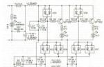
Actually, at this stage the diagram takes its final form (we make the appropriate changes on the diagram - “connect” keys and buttons to the selected pins):

After this, I finish the last connections in the printed circuit board project, “sketch out” the GND polygons (since the laser printer does not print solid polygons well, I make it a “mesh”), add a couple of vias (VIA) from one layer of the board to another and check that there is not a single chain left unbroken.

I got a scarf measuring 56x35mm.
An archive with a schematic and board for Eagle version 6.1.0 (and higher) can be found at this link.
Voila, you can start manufacturing printed circuit board.
PCB manufacturing
I make the board using the LUT (Laser Ironing Technology) method. At the end of the post there is a link to materials that helped me a lot.For the sake of order, I will give the main steps for making the board:
- I print the bottom side of the board on Lomond 130 paper (glossy).
- I print the top side of the board on the same paper (mirrored!).
- I fold the resulting printouts with the images inward and combine them in the light (it is very important to obtain maximum accuracy).
- After this, I fasten the sheets of paper with a stapler (constantly checking that the alignment is not disturbed) on three sides - an “envelope” is obtained.
- I cut out a suitable size piece of double-sided fiberglass (with metal scissors or a hacksaw).
- Fiberglass needs to be treated with very fine sandpaper (remove oxides) and degreased (I do this with acetone).
- I place the resulting workpiece (carefully, by the edges, without touching the cleaned surfaces) into the resulting “envelope”.
- I heat the iron to full and carefully iron the workpiece on both sides.
- I leave the board to cool (5 minutes), after which you can soak the paper under running water and remove it.
I wash off the toner with acetone.
Advice: when making small boards, make a blank for the required number of boards, simply placing images of the upper and lower parts of the board in several copies - and “roll” this “combined” image onto a blank made of fiberglass. After etching, it will be enough to cut the workpiece into separate boards.
Only Necessarily check the dimensions of the boards when inputting onto paper: some programs like to “slightly” change the image scale when outputting, and this is unacceptable.

Quality control
After this, I do a visual inspection (good lighting and a magnifying glass are required). If there is any suspicion that there is a “stuck”, check the “suspicious” places with a tester.For peace of mind - control with a tester everyone adjacent conductors (it is convenient to use the “dialing” mode, when in case of a “short circuit” the tester gives a sound signal).
If, nevertheless, an unnecessary contact is found somewhere, I correct it with a sharp knife. Additionally, I pay attention to possible “microcracks” (for now I’m just fixing them - I’ll fix them at the stage of tinning the board).
Tinning, drilling
I prefer to tin the board before drilling - this way soft solder makes drilling a little easier and the drill at the “exit” of the board “tears” the copper conductors less.First, the manufactured printed circuit board must be degreased (acetone or alcohol); you can “go through” it with an eraser to remove any oxides that have appeared. After that, I cover the board with ordinary glycerin and then use a soldering iron (temperature somewhere around 300 degrees) with a small amount of solder to “drive” along the paths - the solder lies smoothly and beautifully (shiny). You have to tin it quickly enough so that the tracks don’t fall off.
When everything is ready, I wash the board with regular liquid soap.

After this you can drill the board.
With holes with a diameter of more than 1 mm, everything is quite simple (I just drill and that’s it - you just need to try to maintain verticality, then the exit hole will fall into the place allocated for it).

But with vias (I make them with a 0.6mm drill) it’s a little more complicated - the output hole, as a rule, turns out to be a little “ragged” and this can lead to an unwanted break in the conductor.
Here we can advise you to make each hole in two passes: drill first on one side (but so that the drill does not come out on the other side of the board), and then do the same on the other side. With this approach, the “connection” of the holes will occur in the thickness of the board (and slight misalignment will not be a problem).
Installation of elements
First, the interlayer jumpers are soldered.Where these are just vias, I simply insert a piece of copper wire and solder it on both sides.
If the “transition” is carried out through one of the holes for output elements (connectors, relays, etc.): I unravel the stranded wire into thin cores and carefully solder pieces of this core on both sides in those holes where the transition is needed, while taking up minimal space space inside the hole. This allows the transition to be implemented and the holes remain free enough for the corresponding connectors to fit normally into place and be soldered.
Here again we should return to the “quality control” stage - I call the tester all previously suspicious and new places obtained during tinning/drilling/creating transitions.
I check that the previously detected microcracks are eliminated with solder (or I eliminate them by soldering a thin conductor over the crack, if the crack remains after tinning).
I eliminate all “stickies”, if any appeared during the tinning process. This much easier to do now than in the process of debugging an already fully assembled board.
Now you can proceed directly to the installation of elements.
My principle: “bottom up” (first I solder the least tall components, then those that are “higher” and those that are “high”). This approach allows you to place all the elements on the board with less inconvenience.
Thus, first the SMD components are soldered (I start with those elements that have “more legs” - MKs, transistors, diodes, resistors, capacitors), then it comes to the output components - connectors, relays, etc.
Thus, we get a ready-made board.