Reading time: 3 min
BIOS beeps can be very helpful in diagnosing your computer. If the computer does not turn on, but there are sound signals, this will make troubleshooting much easier and by deciphering this sound combination you can understand where to look. Unless, of course, there is a speaker on the motherboard that makes these sounds.
What do 1 long and 2 short beeps mean when you start your computer?
If when you turn on your computer you hear system unit one long and two short signals and nothing is entered on the monitor screen, then most likely the fault lies in the video card or in the connector on the motherboard.
The same signal but very rarely can be due to a malfunction random access memory, depending on the BIOS manufacturer.
There were also cases when such BIOS beeps were played when the motherboard did not support the installed processor, but this option can be immediately eliminated if the processor in the computer did not change.
What to do
Before entering the system unit, turn off the power to the computer.
If 1 long and 2 short beeps means that the problem is in the video card, then let's start with it. We open the case of the system unit, carefully remove the video card in order to wipe the contacts with an eraser and install the video card in place. If the contact simply disappears, then the sound signal should disappear and the computer will turn on. 
If you do not have an external video card and the computer was working through the built-in one, then take an external video card and try to turn on the computer through it. The built-in video card may have failed.
Inspect the motherboard, as well as the video card, for swollen capacitors, this is often the reason that the computer does not turn on. If such capacitors are present, they need to be replaced. You can replace it yourself if you have ever held a soldering iron in your hands. Or take the motherboard to a workshop.

The next step to identify the reason why one long and two short signals are emitted is to extract the RAM. If you have several RAM sticks installed, then remove them all. We wipe them with an eraser, insert one strip into the motherboard, and try to turn it on. If it doesn’t turn on, take out the RAM and insert it into another slot and do this with each stick.

If after all the actions described above and you still hear this beep and if these signals appeared after installing a new processor or assembled new computer, then most likely this signal indicates the incompatibility of the motherboard with the processor, RAM or video card. To check this, you need to go to the official website of the motherboard manufacturer and see what processors and RAM the motherboard is compatible with.
If none of the above helped you, then write in the comments, we will try to help.
Why do you need a BIOS:
1. When the computer boots, it checks for the presence of basic hardware and its functionality. If, for example, RAM, a processor, or another device necessary for PC operation is “burned out,” the BIOS will give a signal with a special sound (the set of signals will be different for each component).
2. The BIOS loads the bootloader, which in turn loads the OS.
3. BIOS allows the OS to communicate with peripheral equipment.
4. BIOS allows you to configure many hardware components, monitor their status and operating parameters. The settings made by the user are saved there, for example, the current date and time, and allows you to turn on and off the equipment built into the motherboard.
To determine the BIOS type
I recommend looking at the time of boot, usually in the upper left part of the screen there is information about the manufacturer and BIOS version, or going into the BIOS settings, usually pressing the Delete key several times after turning on the PC.
UEFI BIOS


|
Description of the error |
|
|
1 short |
|
|
2 short |
There are non-critical errors. |
|
3 long |
The keyboard controller generated an error |
|
1 short + 1 long |
RAM is faulty |
|
1 long + 2 short |
The video card signals an error |
|
1 long + 3 short |
Video memory error |
|
1 long + 9 short |
Error reading from ROM |
|
Continuous short beeps |
Malfunction of the power supply or RAM |
|
Continuous long beeps |
RAM problems |
|
Alternating long and short signals |
Processor failure |
|
Continuous signal |
Indicates problems with the power supply |

| Sequence of beeps | Bios error description |
| 1 short | Successful POST |
| 1 beep and blank screen | Video system is faulty |
| 2 short | Monitor not connected |
| 3 long | Motherboard faulty (keyboard controller error) |
| 1 long 1 short | Motherboard is faulty |
| 1 long 2 short | Video system faulty (Mono/CGA) |
| 1 long 3 short | Video system (EGA/VGA) is faulty |
| Repeating short | Malfunctions related to the power supply or motherboard |
| Continuous | Problems with the power supply or motherboard |
| Absent | The power supply, motherboard, or speaker is faulty |

| Sequence of beeps | Description of the error |
| 1 short | Successful POST |
| 2 short | Minor errors found. A prompt to log in appears on the monitor screen. into the CMOS Setup Utility program and correct the situation. Check the security of the fastening cables in connectors hard drive and motherboard. |
| 3 long | Keyboard controller error |
| 1 short 1 long | Random access memory (RAM) error |
| 1 long 2 short | Video card error |
| 1 long 3 short | Video memory error |
| 1 long 9 short | Error reading from ROM |
| Repeating short | Problems with the power supply; RAM problems |
| Repeating long | RAM problems |
| Repeated high-low frequency | CPU problems |
| Continuous | Problems with the power supply |

| Sequence of beeps | Description of the error |
| 1 short | No errors found, PC is working fine |
| 2 short | RAM parity error or you forgot to turn off the scanner or printer |
| 3 short | Error in the first 64 KB of RAM |
| 4 short | System timer malfunction |
| 5 short | Processor problems |
| 6 short | Keyboard controller initialization error |
| 7 short | Problems with the motherboard |
| 8 short | Video card memory error |
| 9 short | BIOS checksum is incorrect |
| 10 short | CMOS write error |
| 11 short | System board cache error |
| 1 long 1 short | Problems with the power supply |
| 1 long 2 short | Video card error (Mono-CGA) |
| 1 long 3 short | Video card error (EGA-VGA) |
| 1 long 4 short | No video card |
| 1 long 8 short | Problems with the video card or the monitor is not connected |
| 3 long | RAM - Read/Write test completed with error. Reinstall the memory or replace it with a working module. |
| Missing and blank screen | The processor is faulty. The contact leg of the processor may be bent (broken). Check the processor. |
| Continuous beep | The power supply is faulty or the computer is overheating |
AST BIOS
| Sequence of beeps | Description of the error |
| 1 short | Error when checking processor registers. Processor failure |
| 2 short | Keyboard controller buffer error. Keyboard controller malfunction. |
| 3 short | Keyboard controller reset error. The keyboard controller or system board is faulty. |
| 4 short | Keyboard communication error. |
| 5 short | Keyboard error. |
| 6 short | System board error. |
| 9 short | Mismatch checksum BIOS ROM. The BIOS ROM chip is faulty. |
| 10 short | System timer error. The system timer chip is faulty. |
| 11 short | Chipset error. |
| 12 short | Power management register error in non-volatile memory. |
| 1 long | DMA controller error 0. The DMA controller chip on channel 0 is faulty. |
| 1 long 1 short | DMA controller error 1. The channel 1 DMA controller chip is faulty. |
| 1 long 2 short | Frame retrace suppression error. The video adapter may be faulty. |
| 1 long 3 short | Error in video memory. The memory of the video adapter is faulty. |
| 1 long 4 short | Video adapter error. The video adapter is faulty. |
| 1 long 5 short | Memory error 64K. |
| 1 long 6 short | Failed to load interrupt vectors. BIOS was unable to load interrupt vectors into memory |
| 1 long 7 short | Failed to initialize video hardware. |
| 1 long 8 short | Video memory error. |


Phoenix BIOS beeps consist of several series of short beeps at intervals. For example, a signal with code 1-2-3 will sound like this: one short beep, pause, two short beeps, pause, three short beeps.
|
Signal |
Meaning (decoding) |
|
Error when reading data from the built-in CMOS memory chip |
|
|
CMOS chip checksum error |
|
|
Error on system board |
|
|
System board DMA controller error |
|
|
Error reading or writing data to one of the DMA channels |
|
|
Error in RAM |
|
|
Error in the first 64 KB of main memory |
|
|
System board error |
|
|
RAM testing error |
|
|
from 2-1-1 to 2-4-4 |
Error in one of the bits of the first 64 KB of RAM |
|
Error in the first DMA channel |
|
|
Error in the second DMA channel |
|
|
Error processing interrupts |
|
|
Motherboard interrupt controller error |
|
|
Keyboard controller error |
|
|
Video adapter error |
|
|
Error when testing video memory |
|
|
Error while searching for video memory |
|
|
System timer error |
|
|
Completion of testing |
|
|
Keyboard controller error |
|
|
CPU error |
|
|
RAM testing error |
|
|
System timer error |
|
|
Real time clock error |
|
|
Serial port error |
|
|
Parallel port error |
|
|
Math coprocessor error |
|
|
Error in the operation of adapters that have their own BIOS |
|
|
Error when calculating BIOS checksum |
|
|
Error in RAM operation |
|
|
Keyboard controller error |
|
|
Errors when testing RAM |
|
|
Error handling unexpected interrupts |
Sequence of sound signals, description of errors without table:
1-1-2 Error during processor test. The processor is faulty. Replace the processor
1-1-3 Error writing/reading data to/from CMOS memory.
1-1-4 An error was detected when calculating the checksum of the BIOS contents.
1-2-1 Motherboard initialization error.
1-2-2 or 1-2-3 DMA controller initialization error.
1-3-1 Error in initializing the RAM regeneration circuit.
1-3-3 or 1-3-4 Error initializing the first 64 KB of RAM.
1-4-1 Motherboard initialization error.
1-4-2 Error initializing RAM.
1-4-3 Error initializing the system timer.
1-4-4 Error writing/reading to/from one of the I/O ports.
2-1-1 An error was detected while reading/writing bit 0 (in hexadecimal) of the first 64 KB of RAM
2-1-2 An error was detected when reading/writing the 1st bit (in hexadecimal) of the first 64 KB of RAM
2-1-3 An error was detected when reading/writing the 2nd bit (in hexadecimal) of the first 64 KB of RAM
2-1-4 An error was detected when reading/writing the 3rd bit (in hexadecimal) of the first 64 KB of RAM
2-2-1 An error was detected when reading/writing the 4th bit (in hexadecimal) of the first 64 KB of RAM
2-2-2 An error was detected when reading/writing the 5th bit (in hexadecimal) of the first 64 KB of RAM
2-2-3 An error was detected when reading/writing the 6th bit (in hexadecimal) of the first 64 KB of RAM
2-2-4 An error was detected when reading/writing the 7th bit (in hexadecimal) of the first 64 KB of RAM
2-3-1 An error was detected when reading/writing the 8th bit (in hexadecimal) of the first 64 KB of RAM
2-3-2 An error was detected when reading/writing the 9th bit (in hexadecimal) of the first 64 KB of RAM
2-3-3 An error was detected when reading/writing the 10th bit (in hexadecimal) of the first 64 KB of RAM
2-3-4 An error was detected when reading/writing the 11th bit (in hexadecimal) of the first 64 KB of RAM
2-4-1 An error was detected while reading/writing the 12th bit (in hexadecimal) of the first 64 KB of RAM
2-4-2 An error was detected when reading/writing the 13th bit (in hexadecimal) of the first 64 KB of RAM
2-4-3 An error was detected when reading/writing the 14th bit (in hexadecimal) of the first 64 KB of RAM
2-4-4 An error was detected when reading/writing the 15th bit (in hexadecimal) of the first 64 KB of RAM
3-1-1 Error initializing the second DMA channel.
3-1-2 or 3-1-4 Error initializing the first DMA channel.
3-2-4 Keyboard controller initialization error.
3-3-4 Error initializing video memory.
3-4-1 Serious problems occurred when trying to access the monitor.
3-4-2 The video card BIOS cannot be initialized.
4-2-1 System timer initialization error.
4-2-2 Testing completed.
4-2-3 Keyboard controller initialization error.
4-2-4 Critical error when the central processor enters protected mode.
4-3-1 Error initializing RAM.
4-3-2 Error initializing the first timer.
4-3-3 Error in initializing the second timer.
4-4-1 Error initializing one of the serial ports.
4-4-2 Parallel port initialization error.
4-4-3 Math coprocessor initialization error.
Long, continuous beeps—the motherboard is faulty.
The sound of a siren from high to low frequency means the video card is faulty, check the electrolytic capacitors for leaks or replace everything with new ones that are known to be good.
Continuous signal - the CPU cooler is not connected (faulty).
In contact with
Probably, almost every computer user has noticed that when starting up, a characteristic sound is heard, similar to a squeak. In most cases, if all is well, there will be one short beep. Thus, the system informs us about the state of the PC even during startup, before Windows loads.
BIOS(Basic Input/Output System – basic system input/output) is a system-level program located in the BIOS microprocessor. Intended for the initial startup of the computer, it is loaded first after turning on the computer.
When the system starts, the BIOS starts the computer and performs a self-test (Power-On Self Test - POST) to perform general diagnostics of the system and if there are problems, the computer will emit a certain sequence of signals that you only have to decipher.
If you don't hear any sounds, then it's possible that you have a missing speaker on your motherboard. In the event of a computer malfunction, the absence of a speaker makes it a little more difficult to find the problem, but is not critical.

In modern motherboards, the speaker began to be built-in. On older models, the speaker was connected to the board.
BIOS Manufacturer
Each BIOS manufacturer has its own sequence and interpretation of sound signals. Before you begin decoding, you need to find out the manufacturer.
Method 1

The easiest way to determine the company is at the time of boot, usually indicating the manufacturer and BIOS version.
Method 2
You can go into the BIOS during startup and find the “System Information” item or using the Everest (Aida) program in Windows. In both cases, all information will be indicated.

That's it now modern computers come out with an updated BIOS called UEFI.
Now that we know the BIOS manufacturer, it will not be difficult for us to decipher the sound signals.
AMI BIOS
|
Signal |
Meaning (decoding) |
|
1 short |
No errors found |
|
2 short |
RAM parity error |
|
3 short |
Malfunction of the first 64 KB of RAM |
|
4 short |
System timer is faulty |
|
5 short |
Processor failure |
|
6 short |
Keyboard controller malfunction |
|
7 short |
System board failure |
|
8 short |
Video memory error |
|
9 short |
Incorrect BIOS checksum |
|
10 short |
CMOS memory write error |
|
11 short |
Cache error |
|
1 long 2 short |
Video adapter is faulty |
|
1 long 3 short |
|
|
2 long 2 short |
Floppy controller error |
|
No signals |
AWARD BIOS
|
Signal |
Meaning (decoding) |
|
1 short |
No errors found |
|
Continuous or short repetitive |
The power supply is faulty or there is a short circuit in the power supply circuits |
|
1 long or long repeating |
RAM error |
|
1 long 2 short |
Video adapter not detected or video memory error |
|
1 long 3 short |
Video adapter error or keyboard error |
|
3 long |
Keyboard controller error |
|
1 long 9 short |
BIOS read error or BIOS chip is faulty |
|
2 short |
A non-critical error was detected. |
|
No signals |
The power supply or system board is faulty |
Phoenix BIOS
Phoenix BIOS beeps consist of several series of short beeps at intervals. For example, a signal with code 1-2-3 will sound like this: one short beep, pause, two short beeps, pause, three short beeps.
|
Signal |
Meaning (decoding) |
|
Error when reading data from the built-in CMOS memory chip |
|
|
CMOS chip checksum error |
|
|
Error on system board |
|
|
System board DMA controller error |
|
|
Error reading or writing data to one of the DMA channels |
|
|
Error in RAM |
|
|
Error in the first 64 KB of main memory |
|
|
System board error |
|
|
RAM testing error |
|
|
from 2-1-1 to 2-4-4 |
Error in one of the bits of the first 64 KB of RAM |
|
Error in the first DMA channel |
|
|
Error in the second DMA channel |
|
|
Error processing interrupts |
|
|
Motherboard interrupt controller error |
|
|
Keyboard controller error |
|
|
Video adapter error |
|
|
Error when testing video memory |
|
|
Error while searching for video memory |
|
|
System timer error |
|
|
Completion of testing |
|
|
Keyboard controller error |
|
|
CPU error |
|
|
RAM testing error |
|
|
System timer error |
|
|
Real time clock error |
|
|
Serial port error |
|
|
Parallel port error |
|
|
Math coprocessor error |
|
|
Error in the operation of adapters that have their own BIOS |
|
|
Error when calculating BIOS checksum |
|
|
Error in RAM operation |
|
|
Keyboard controller error |
|
|
Errors when testing RAM |
|
|
Error handling unexpected interrupts |
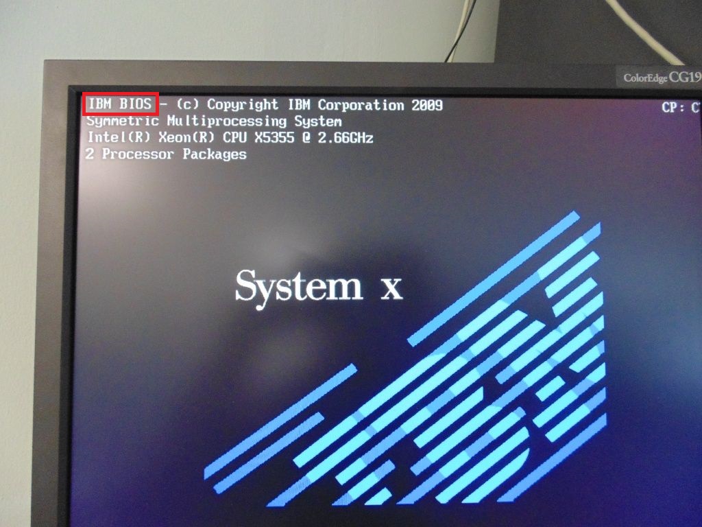
IBM BIOS
|
Signal |
Meaning (decoding) |
|
1 short |
No errors found |
|
1 beep and blank screen |
Video adapter is faulty |
|
2 short |
Video adapter is faulty |
|
3 long |
Motherboard faulty (keyboard controller error), RAM faulty |
|
1 long, 1 short |
Motherboard is faulty |
|
1 long, 2 short |
Video system faulty (Mono/CGA) |
|
1 long, 3 short |
Video system (EGA/VGA) is faulty |
|
Repeating short |
Malfunctions related to the power supply or motherboard |
|
Continuous |
The power supply or system board is faulty |
|
Absent |
The power supply, motherboard, or speaker is faulty |
AST BIOS
|
Signal |
Meaning (decoding) |
|
1 short |
Error when checking processor registers. Processor failure |
|
2 short |
Keyboard controller buffer error. Keyboard controller malfunction. |
|
3 short |
Keyboard controller reset error. The keyboard controller or system board is faulty. |
|
4 short |
Keyboard communication error. |
|
5 short |
Keyboard error. |
|
6 short |
System board error. |
|
9 short |
BIOS ROM checksum mismatch. The BIOS ROM chip is faulty. |
|
10 short |
System timer error. The system timer chip is faulty. |
|
11 short |
System logic chip (chipset) error. |
|
12 short |
Power management register error in non-volatile memory. |
|
1 long |
DMA controller error 0. The DMA controller chip on channel 0 is faulty. |
|
1 long, 1 short |
DMA controller error 1. The channel 1 DMA controller chip is faulty. |
|
1 long, 2 short |
Frame retrace suppression error. The video adapter may be faulty. |
|
1 long, 3 short |
Error in video memory. The memory of the video adapter is faulty. |
|
1 long, 4 short |
Video adapter error. The video adapter is faulty. |
|
1 long, 5 short |
Memory error 64K. |
|
1 long, 6 short |
Failed to load interrupt vectors. BIOS was unable to load interrupt vectors into memory |
|
1 long, 7 short |
The video subsystem failed to initialize. |
|
1 long, 8 short |
Video memory error. |
Compaq BIOS
|
Signal |
Meaning (decoding) |
|
1 short |
No errors found |
|
1 long + 1 short |
BIOS CMOS memory checksum error. The ROM battery may have run out. |
|
2 short |
Global error. |
|
1 long + 2 short |
Error initializing video card. Check that the video card is installed correctly. |
|
7 beeps (1 long, 1 s, 1?, 1 short, pause, 1 long, 1 short, 1 short) |
AGP video card malfunction. Check that the installation is correct. |
|
1 long constant |
RAM error, try rebooting. |
|
1 short + 2 long |
RAM malfunction. Reboot via Reset. |
DELL BIOS
As with the Phoenix BIOS, the DELL BIOS uses a similar signaling system. For example, 1-3-1-1 would sound like this: one beep, pause, three beeps, pause, one beep, pause, one beep.
|
Signal |
Meaning (decoding) |
|
Video card not connected |
|
|
BIOS ROM checksum error |
|
|
DRAM update error |
|
|
Keyboard error 8742 |
|
|
Memory faulty |
|
|
RAM error on line xxx |
|
|
RAM error on least significant bit xxx |
|
|
1-4-1-1 test |
RAM error on high bit xxx |
Quadtel BIOS
|
Signal |
Meaning (decoding) |
|
1 short beep |
No errors found |
|
2 short beeps |
CMOS RAM is damaged. Replace IC if possible |
|
1 long, 2 short beeps |
Video adapter error. The video adapter is faulty. Reinstall the video adapter or replace the adapter if possible |
|
1 long, 3 short beeps |
One or more of the peripheral controllers is faulty. Replace controllers and retest |
UEFI BIOS
|
Signal |
Meaning (decoding) |
|
1 short |
|
|
2 short |
There are non-critical errors. |
|
3 long |
The keyboard controller generated an error |
|
1 short + 1 long |
RAM is faulty |
|
1 long + 2 short |
The video card signals an error |
|
1 long + 3 short |
Video memory error |
|
1 long + 9 short |
Error reading from ROM |
|
Continuous short beeps |
Malfunction of the power supply or RAM |
|
Continuous long beeps |
RAM problems |
|
Alternating long and short signals |
Processor failure |
|
Continuous signal |
Indicates problems with the power supply |
One long and two short BIOS beeps mean that during a hardware check, a problem was detected with one of the devices. In this case, nothing is usually displayed on the screen.
What does one long and two short BIOS beeps mean?
BIOS can be different versions, so this combination of signals can indicate different hardware problems. In most BIOS versions, one long and two short beeps mean that a problem has been detected with the video card (which problem depends on the BIOS version). The main BIOS versions and signal decoding for them are described below:
AST BIOS and Award BIOS - this combination of sounds is generated if there is a problem with the video card;
IBM BIOS and AMI BIOS. This signal is generated only if the computer is equipped with Mono/CGA video cards and they do not respond. In recent years, they have hardly been used, so the likelihood of encountering such a signal in this BIOS version is very low;
Compaq BIOS and Quadtel BIOS. Such signals mean that there was an error in initializing the video card.
How to fix the problem?
In order for the computer to start normally, try removing the video card and wiping all contacts with a dry cloth. If dirt has stuck to them (or stains are visible), wipe it off with a regular office eraser. Insert the video card back and turn on the computer. If this method does not help, you will need to contact the service; most likely, a technical problem has arisen.

Since Bios versions are constantly updated, one long and two short beeps may mean something else. In this case, you need to look at the Bios version and then search the Internet for this error for a specific software version.
Or ask us by writing your question in the comments right below this answer. We will definitely help you!
Error Message | Description |
|
System is booting properly |
||
BIOS ROM checksum error | The contents of the BIOS ROM to not match the expected contents. If possible, reload the BIOS from the PAQ |
|
Check the video adapter and ensure it"s seated properly. If possible, replace the video adapter |
||
7 beeps (1 long, 1s, 1l, 1 short, pause, 1 long, 1 short, 1 short) | The AGP video card is faulty. Reseat the card or replace it outright. This beep pertains to Compaq Deskpro systems |
|
1 long never ending beep | Memory error. Bad RAM. Replace and test | |
Reseat RAM then retest; replace RAM if failure continues |
Error Message | Description |
|
System is booting properly |
||
Initialization error | Error code is displayed |
|
System board error | ||
Video adapter error | ||
EGA/VGA adapter error | ||
3270 keyboard adapter error | ||
Power supply error | Replace the power supply |
|
Power supply error | Replace the power supply |
|
Replace the power supply |
Beeps/Error | Description |
Continuous beeping | System board failure |
One beep; Unreadable, blank or flashing LCD | LCD connector problem; LCD backlight inverter failure; video adapter faulty; LCD assembly faulty; System board failure; power supply failure |
One beep; Message "Unable to access boot source" | Boot device failure; system board failure |
One long, two short beeps | System board failure; Video adapter problem; LCD assembly failure |
One long, four short beeps | Low battery voltage |
One beep every second | Low battery voltage |
Two short beeps with error codes | POST error message |
System board failure |
IBM Intellistation BIOS:
Beep error code: | Action / Run diagnostics on the following components: |
| 1-1-3 CMOS read/write error | 1.Run Setup 2.System Board |
| 1-1-4 ROM BIOS check error | 1.System Board |
| 1-2-X DMA error | 1.System Board |
| 1-3-X | 1.Memory Module 2.System Board |
| 1-4-4 | 1. Keyboard 2.System Board |
| 1-4-X Error detected in first 64 KB of RAM. | 1.Memory Module 2.System Board |
| 2-1-1, 2-1-2 | 1.Run Setup 2.System Board |
| 2-1-X First 64 KB of RAM failed. | 1.Memory Module 2.System Board |
| 2-2-2 | 2.System Board |
| 2-2-X First 64 KB of RAM failed. | 1.Memory Module 2.System Board |
| 2-3-X | 1.Memory Module 2.System Board |
| 2-4-X | 1.Run Setup 2. Memory Module 3.System Board |
| 3-1-X DMA register failed. | 1.System Board |
| 3-2-4 Keyboard controller failed. | 1.System Board 2. Keyboard |
| 3-3-4 Screen initialization failed. | 1. Video Adapter (if installed) 2.System Board 3.Display |
| 3-4-1 Screen retrace detected an error. | 1. Video Adapter (if installed) 2.System Board 3.Display |
| 3-4-2 POST is searching for video ROM. | 1. Video Adapter (if installed) 2.System Board |
| 4 | 1. Video Adapter (if installed) 2.System Board |
| All other beep code sequences. | 1.System Board |
| One long and one short beep during POST. Base 640 KB memory error or shadow RAM error. | 1.Memory Module 2.System Board |
| One long beep and two or three short beeps during POST.(Video error) | 1. Video Adapter (if installed) 2.System Board |
| Three short beeps during POST. | 1. See "System board memory" on page 62. 2.System Board |
| Continuous beep. | 1.System Board |
| Repeating short beeps. | 1. Keyboard stuck key? 2.Keyboard Cable 3.System Board |
Error Message | Description |
|
System is booting normally |
||
Video adapter error | The video adapter is either faulty or not seated properly. Check the adapter |
|
Keyboard controller error | The keyboard controller IC is faulty. Replace the IC if possible |
|
The keyboard controller IC is faulty or the keyboard is faulty. Replace the keyboard, if problem still persists, replace the keyboard controller IC |
||
The programmable interrupt controller is faulty. Replace the IC if possible |
||
The programmable interrupt controller is faulty. replace the IC if possible |
||
DMA page register error | The DMA controller IC is faulty. Replace the IC if possible |
|
RAM refresh error | ||
RAM parity error | ||
DMA controller 0 error | The DMA controller IC for channel 0 has failed |
|
The CMOS RAM has failed |
||
DMA controller 1 error | The DMA controller IC for channel 1 has failed |
|
CMOS RAM battery error | The CMOS RAM battery has failed. If possible, replace the CMOS or battery |
|
CMOS RAM checksum error | The CMOS RAM has failed. If possible, replace the CMOS |
|
BIOS ROM checksum error | The BIOS ROM has failed. If possible replace the BIOS or upgrade it |
Error Message | Description |
|
System is booting normally |
||
Video adapter failure | Either the video adapter is faulty, not seated properly or is missing |
|
1 long, 1 short, 1 long | Keyboard controller error | Either the keyboard controller IC is faulty or the system board circuitry is faulty |
1 long, 2 short, 1 long | Either the keyboard controller is faulty or the system board circuitry is faulty |
|
1 long, 3 short, 1 long | ||
1 long 4 short, 1 long | The programmable interrupt controller IC is faulty |
|
1 long, 5 short, 1 long | DMA page register error | The DMA controller IC 1 or 2 is faulty or the system board circuitry is faulty |
1 long, 6 short, 1 long | RAM refresh error | |
1 long, 7 short, 1 long | ||
1 long, 8 short, 1 long | RAM parity error |
|
1 long, 9 short, 1 long | DMA controller 1 error | The DMA controller for channel 0 is faulty or the system board circuitry is faulty |
1 long, 10 short, 1 long | Either the CMOS RAM is faulty. Replace the CMOS |
|
1 long, 11 short, 1 long | DMA controller 2 error | The DMA controller for channel 1 is faulty or the system board circuitry is faulty |
1 long, 12 short, 1 long | CMOS RAM battery error | The CMOS RAM battery is faulty or the CMOS RAM is bad. Replace the battery if possible |
1 long, 13 short, 1 long | CMOS checksum error | The CMOS RAM is faulty |
1 long 14 short, 1 long | BIOS ROM checksum failure | The BIOS ROM checksum is faulty. Replace the BIOS or upgrade |
Phoenix ISA/MCA/EISA BIOS:
The beep codes are represented in the number of beeps. E.g. 1-1-2 would mean 1 beep, a pause, 1 beep, a pause, and 2 beeps.
- With a Dell computer, a 1-2 beep code can also indicate that a bootable add-in card is installed but no boot device is attached. For example, in you insert a Promise Ultra-66 card but do not connect a hard drive to it, you will get the beep code. I verified this with a SIIG (crap -- avoid like the plague) Ultra-66 card, and then confirmed the results with Dell.
Error Message | Description |
|
CPU test failure | The CPU is faulty. Replace the CPU |
|
System board select failure | The motherboard is having an undetermined fault. Replace the motherboard |
|
CMOS read/write error | The real time clock/CMOS is faulty. Replace the CMOS if possible |
|
Extended CMOS RAM failure | The extended portion of the CMOS RAM has failed. Replace the CMOS if possible |
|
BIOS ROM checksum error | The BIOS ROM has failed. Replace the BIOS or upgrade if possible |
|
The programmable interrupt timer has failed. Replace if possible |
||
DMA read/write failure | The DMA controller has failed. Replace the IC if possible |
|
RAM refresh failure | The RAM refresh controller has failed |
|
64KB RAM failure | The test of the first 64KB RAM has failed to start |
|
First 64KB RAM failure | The first RAM IC has failed. Replace the IC if possible |
|
First 64KB logic failure | The first RAM control logic has failed |
|
Address line failure | The address line to the first 64KB RAM has failed |
|
Parity RAM failure | The first RAM IC has failed. Replace if possible |
|
EISA fail-safe timer test | Replace the motherboard |
|
EISA NMI port 462 test | Replace the motherboard |
|
64KB RAM failure | Bit 0; This data bit on the first RAM IC has failed. Replace the IC if possible |
|
64KB RAM failure | Bit 1; This data bit on the first RAM IC has failed. Replace the IC if possible |
|
64KB RAM failure | Bit 2; This data bit on the first RAM IC has failed. Replace the IC if possible |
|
64KB RAM failure | Bit 3; This data bit on the first RAM IC has failed. Replace the IC if possible |
|
64KB RAM failure | Bit 4; This data bit on the first RAM IC has failed. Replace the IC if possible |
|
64KB RAM failure | Bit 5; This data bit on the first RAM IC has failed. Replace the IC if possible |
|
64KB RAM failure | Bit 6; This data bit on the first RAM IC has failed. Replace the IC if possible |
|
64KB RAM failure | Bit 7; This data bit on the first RAM IC has failed. Replace the IC if possible |
|
64KB RAM failure | Bit 8; This data bit on the first RAM IC has failed. Replace the IC if possible |
|
64KB RAM failure | Bit 9; This data bit on the first RAM IC has failed. Replace the IC if possible |
|
64KB RAM failure | Bit 10; This data bit on the first RAM IC has failed. Replace the IC if possible |
|
64KB RAM failure | Bit 11; This data bit on the first RAM IC has failed. Replace the IC if possible |
|
64KB RAM failure | Bit 12; This data bit on the first RAM IC has failed. Replace the IC if possible |
|
64KB RAM failure | Bit 13; This data bit on the first RAM IC has failed. Replace the IC if possible |
|
64KB RAM failure | Bit 14; This data bit on the first RAM IC has failed. Replace the IC if possible |
|
64KB RAM failure | Bit 15; This data bit on the first RAM IC has failed. Replace the IC if possible |
|
Slave DMA register failure | The DMA controller has failed. Replace the controller if possible |
|
Master DMA register failure | The DMA controller had failed. Replace the controller if possible |
|
Master interrupt mask register failure | ||
Slave interrupt mask register failure | The interrupt controller IC has failed |
|
Interrupt vector error | The BIOS was unable to load the interrupt vectors into memory. Replace the motherboard |
|
Keyboard controller failure | ||
CMOS RAM power bad | Replace the CMOS battery or CMOS RAM if possible |
|
CMOS configuration error | The CMOS configuration has failed. Restore the configuration or replace the battery if possible |
|
Video memory failure | There is a problem with the video memory. Replace the video adapter if possible |
|
Video initialization failure | There is a problem with the video adapter. Reseat the adapter or replace the adapter if possible |
|
The system's timer IC has failed. Replace the IC if possible |
||
Shutdown failure | The CMOS has failed. Replace the CMOS IC if possible |
|
Gate A20 failure | The keyboard controller has failed. Replace the IC if possible |
|
Unexpected interrupt in protected mode | This is a CPU problem. Replace the CPU and retest |
|
RAM test failure | System RAM addressing circuitry is faulty. Replace the motherboard |
|
Interval timer channel 2 failure | The system timer IC has failed. Replace the IC if possible |
|
Time of day clock failure | The real time clock/CMOS has failed. Replace the CMOS if possible |
|
Serial port failure | A error has occurred in the serial port circuitry |
|
Parallel port failure | A error has occurred in the parallel port circuitry |
|
Math coprocessor failure | The math coprocessor has failed. If possible, replace the MPU |
Description |
|
Verify real mode |
|
Initialize system hardware |
|
Initialize chipset registers with initial values |
|
Set in POST flag |
|
Initialize CPU registers |
|
Initialize cache to initial values |
|
Initialize power management |
|
Load alternative registers with initial POST values |
|
Jump to UserPatch0 |
|
Initialize timer initialization |
|
8254 timer initialization |
|
8237 DMA controller initialization |
|
Reset Programmable Interrupt Controller |
|
Test DRAM refresh |
|
Test 8742 Keyboard Controller |
|
Set ES segment register to 4GB |
|
Clear 512K base memory |
|
Test 512K base address lines |
|
Test 51K base memory |
|
Test CPU bus-clock frequency |
|
CMOS RAM read/write failure (this commonly indicates a problem on the ISA bus such as a card not seated) |
|
Reinitialize the chipset |
|
Shadow system BIOS ROM |
|
Reinitialize the cache |
|
Autosize the cache |
|
Configure advanced chipset registers |
|
Load alternate registers with CMOS values |
|
Set initial CPU speed |
|
Initialize interrupt vectors |
|
Initialize BIOS interrupts |
|
Check ROM copyright notice |
|
Initialize manager for PCI Options ROMs |
|
Check video configuration against CMOS |
|
Initialize PCI bus and devices |
|
initialize all video adapters in system |
|
Shadow video BIOS ROM |
|
Display copyright notice |
|
Display CPU type and speed |
|
Set key click if enabled |
|
Test for unexpected interrupts |
|
Display prompt "Press F2 to enter setup" |
|
Test RAM between 512K and 640K |
|
Test expanded memory |
|
Test extended memory address lines |
|
Jump to UserPatch1 |
|
Configure advanced cache registers |
|
Enable external and CPU caches |
|
Initialize SMI handler |
|
Display external cache size |
|
Display shadow message |
|
Display non-disposable segments |
|
Display error messages |
|
Check for configuration errors |
|
Test real-time clock |
|
Check for keyboard errors |
|
Setup hardware interrupt vectors |
|
Test coprocessor if present |
|
Disable onboard I/O ports |
|
Detect and install external RS232 ports |
|
Detect and install external parallel ports |
|
Reinitialize onboard I/O ports |
|
Initialize BIOS Data Area |
|
Initialize Extended BIOS Data Area |
|
Initialize floppy controller |
|
Initialize hard disk controller |
|
Initialize local bus hard disk controller |
|
Jump to UserPatch2 |
|
Disable A20 address line |
|
Clear huge ES segment register |
|
Search for option ROMs |
|
Shadow option ROMs |
|
Setup power management |
|
Enable hardware interrupts |
|
Scan for F2 keystroke |
|
Clear in-POST flag |
|
Check for errors |
|
POST done - prepare to boot operating system |
|
Check password (optional) |
|
Clear global descriptor table |
|
Clear parity checkers |
|
Check virus and backup reminders |
|
Try to boot with INT 19 |
|
Interrupt handler error |
|
Unknown interrupt error |
|
Pending interrupt error |
|
Initialize option ROM error |
|
Extended Block Move |
|
Shutdown 10 error |
|
Keyboard Controller failure (most likely problem is with RAM or cache unless no video is present) |
|
Initialize the chipset |
|
Initialize refresh counter |
|
Check for Forced Flash |
|
Do a complete RAM test |
|
Do OEM initialization |
|
Initialize interrupt controller |
|
Read in bootstrap code |
|
Initialize all vectors |
|
Initialize the boot device |
|
Boot code was read OK |
Quadtel BIOS:
Error Messages | Description |
|
System is booting normally |
||
The CMOS RAM is faulty. Replace the IC if possible |
||
The video adapter is faulty. Reseat the video adapter or replace the adapter if possible |
||
Peripheral controller error | One or more of the system peripheral controllers is bad. Replace the controllers and retest |