AND Arduino here is no exception, after the LED blinks, it tries to connect the button and use it to control the blinking of this very LED. There is nothing particularly complicated here, but there is one nuance called “contact bounce”. How to properly connect a button to Arduino What is “contact bounce”, how does this effect manifest itself and methods of combating it will be discussed today.
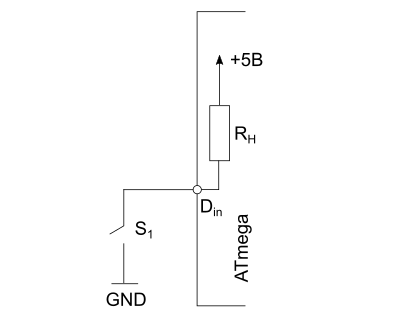
The simplest diagram for connecting a button to a microcontroller looks like this:
If the key S 1 is open (the button is released), then at the digital input D in microcontroller we will have a voltage of 5V, corresponding to a logical one. When the button is pressed, enter D in connects to ground, which corresponds to the logical zero level and all the voltage will drop across the resistor R 1, the value of which is chosen based on the fact that when the button is pressed, not too much current flows through it (usually about 10÷100 kOhm).
If you just connect a button between the digital input and ground (without a resistor R 1, connected to +5V) or between the input and +5V, then in the position when the button is not pressed, an undefined voltage will be present on the digital input of the microcontroller (may correspond to level 0, or maybe 1) and we would read random states. Therefore a resistor is used R 1, which is said to “pull up” the input to +5V when the button is released.
By reading the state of the digital input of the microcontroller, we can determine whether the button is pressed (logical 0 state) or not (we will receive a logical one at the input).
Connecting a button to Arduino
Microcontrollers Atmel AVR ATmega(on the basis of which it is built Arduino) have built-in software-connected load resistors R n 20 kOhm and we can use them by simplifying the connection diagram.
The internal load resistor is connected by writing a logical one to the required bit of the port.
Sketch example Arduino, which turns the built-in LED on pin 13 on and off, depending on whether the button connected to the second pin is pressed or released, using an internal load resistor:
void setup() ( pinMode(13, OUTPUT); //LED on pin 13 pinMode(2, INPUT); //2 pins are in input mode. The button is connected to ground. digitalWrite(2, HIGH); //connect the pull-up resistor ) void loop() ( digitalWrite(13, !digitalRead(2)); // read the button state and switch the LED )
Here we invert the value read from the input port by using a Boolean NOT, denoted by an exclamation mark before the function digitalRead, since when the button is pressed we read 0, and to turn on the LED to the port we need to send 1.
Contact bounce
Everything would be fine if we lived in an ideal world with perfect buttons. Real mechanical contacts that are present in buttons never close or open instantly. Over a short period of time, the contacts of the key (button) are repeatedly closed and opened, as a result of which not a single voltage drop, but a whole packet of pulses is received at the input of the microcontroller. This phenomenon is called “contact bounce”.
In the example above, when we simply turned the LED on and off using a button, we did not notice this, since turning the LED on/off at the moment of “bouncing” happened very quickly and we simply did not see it with our eyes.
This library includes the following methods:
- bounce()— initialization of the Bounce object
- void interval (unsigned long interval)— sets the anti-bounce time in milliseconds
- void attach (int pin)— sets the pin to which the button is connected and connects the built-in pull-up resistor to this pin
- int update()- because the Bounce doesn't use , you are "updating" the object before you read its state and this needs to be done constantly (for example, inside loop). Method update updates the object and returns TRUE(1), if the state of the pin has changed (the button was pressed or, conversely, released) and FALSE(0) otherwise. Calling a Method update inside loop only needs to be done once.
- int read()— returns the updated state of the pin
By default, the Bounce library uses a stabilization interval ( stable interval) to implement anti-bounce. This is easier to understand and eliminates the need to know the duration of the chatter.

Parameter stable interval Bounce libraries
Having determined
#define BOUNCE_LOCK-OUT
#define BOUNCE_LOCK-OUT |
in file Bounce.h You can enable an alternative anti-battering method. This method allows you to react faster to changes in the state of the button, however, it requires setting the duration of the bounce, and this value, as I noted above, increases over time, which means you will need to make changes to the code, or set a deliberately larger value.

Here's an example of using this library:
#include
#include Bounce bouncer = Bounce () ; //create an instance of the Bounce class void setup() pinMode(2, INPUT); // button on pin 2 digitalWrite(2, HIGH); // connect the built-in pull-up resistor bouncer. attach(2); // set the button bouncer. interval(5); // set the parameter stable interval = 5 ms Serial. begin(9600); //set the Serial port to 9600 bps void loop() if (bouncer . update () ) { //if an event occurred if (bouncer . read () == 0 ) { //if the button is pressed Serial. println("pressed"); //display a message about pressing else Serial . println("released"); //output message about release |
And one more small practically useful example. Let us have a button that, when pressed for less than 2 seconds, changes a variable current_mode, which stores the current operating mode of a device. In this example, the mode will change from 0 to 5. Pressed once - the mode is numbered 1. Pressed again - 2. And so on until five. After five, with the next press, the current mode becomes the first and again in a circle. If you hold the button pressed for more than 2 seconds, the variable current_mode is assigned the value 0.
#include
#include #define pressed_long 2000 // long press = 2 seconds #define num_modes 5 // maximum mode number short int max_mode = num_modes + 1 ; // auxiliary variable Bounce bouncer = Bounce () ; //create an instance of the Bounce class unsigned long pressed_moment ; // moment the button is pressed int current_mode = 0 ; // current mode void setup() pinMode(2, INPUT); // button on pin 2 digitalWrite(2, HIGH); // connect the built-in pull-up resistor bouncer. attach(2); // set the button bouncer. interval(5); // set the parameter stable interval = 5 ms |
Instructions
Buttons are different, but they all perform the same function - they physically connect (or, conversely, break) conductors together to ensure electrical contact. In the simplest case, this is the connection of two conductors; there are buttons that connect a larger number of conductors.
Some buttons leave the conductors connected after being pressed (locking buttons), while others open the circuit immediately after being released (non-locking buttons).
Buttons are also divided into normally open and normally closed. The first ones, when pressed, close the circuit, the second ones open the circuit.
Nowadays a type of buttons called “tact buttons” has found widespread use. Clock - not from the word "tact", but rather from the word "tactile", because The pressure is felt well by the fingers. These are buttons that, when pressed, close an electrical circuit, and when released, open them.
A button is a very simple and useful invention that serves for better interaction between man and technology. But, like everything in nature, it is not ideal. This manifests itself in the fact that when you press the button and when you release it, the so-called. " " ("bounce" in -). This is the switching of a button's state multiple times over a short period of time (on the order of a few milliseconds) before it assumes a steady state. This undesirable phenomenon occurs when the button is switched due to the elasticity of the button materials or due to electrical microsparks generated.
You can see it with your own eyes using Arduino, which we will do a little later.

To connect a normally open clock button to the Arduino, you can do it in the simplest way: connect one free conductor of the button to power or ground, the other to the digital output of the Arduino. But, generally speaking, this is wrong. The fact is that at moments when the button is not closed, electromagnetic interference will appear on the Arduino digital output, and because of this, false positives are possible.
To avoid interference, the digital pin is usually connected through a fairly large resistor (10 kOhm) either to ground or to power. In the first case it is called “with a pull-up resistor”, in the second - “circuit with a pull-down resistor”. Let's look at each of them.

First, we connect the button to the Arduino using a circuit with a pull-up resistor. To do this, we connect one contact of the button to ground, the second to digital output 2. Digital output 2 is also connected through a 10 kOhm resistor to the +5 V supply.

Let's write a sketch like this to process button presses and upload it to Arduino.
Now the built-in LED on pin 13 is constantly lit until the button is pressed. When we press the button, it changes to the LOW state and the LED goes off.

Now let's assemble a circuit with a pull-down resistor. We connect one contact of the button to the +5 V power supply, the second to digital output 2. We connect digital output 2 through a 10 kOhm resistor to ground.
We won't change the sketch.

Now the LED does not light until the button is pressed.

Video on the topic
Tip 2: How to get rid of contact bounce when connecting a button to Arduino
We have already looked at connecting a button to Arduino and touched on the issue of contact “bouncing”. This is a very unpleasant phenomenon that causes repeated button presses and complicates the software processing of button presses. Let's talk about how to get rid of contact bounce.

You will need
- - Arduino;
- - tact button;
- - resistor with a nominal value of 10 kOhm;
- - Light-emitting diode;
- - connecting wires.
Instructions
Contact bounce is a phenomenon characteristic of mechanical switches, buttons, toggle switches and relays. Due to the fact that the contacts are usually made of metals and alloys that have elasticity, when physically closed they do not immediately establish a reliable connection. Over a short period of time, the contacts close and repel each other several times. As a result, the electric current does not take on a steady value instantly, but after a series of rises and falls. The duration of this transient effect depends on the material of the contacts, their size and design. The illustration shows a typical waveform when the contacts of a tact button are closed. It can be seen that the time from the moment of switching to the steady state is several milliseconds. This is also "bouncing".
This effect is not noticeable in electrical lighting controls, or other inertial sensors and devices. But in circuits where there is fast reading and processing of information (where frequencies are of the same order as the “bounce” pulses, or higher), this is a problem. In particular, the Arduino UNO, which runs at 16 MHz, is excellent at pin bouncing, accepting a sequence of ones and zeros instead of a single switch from 0 to 1.

Let's look at how contact bounce affects the correct operation of the circuit. Let's connect a clock button to the Arduino using a circuit with a pull-down resistor. When the button is pressed, we will light the LED and leave it on until the button is pressed again. For clarity, let’s connect an external LED to digital pin 13, although you can get by with a built-in one.

To implement this task, the first thing that comes to mind is:
- remember the previous state of the button;
- compare with the current state;
- if the state has changed, then change the state of the LED.
Let's write such a sketch and load it into the Arduino memory.
When the circuit is put into operation, the effect of contact bounce is immediately visible. It manifests itself in the fact that the LED does not light up immediately after pressing the button, or lights up and immediately goes out, or does not turn off immediately after pressing the button, but continues to light. In general, the scheme does not work stably. And if for the task of turning on the LED this is not so critical, then for other, more serious tasks, this is simply unacceptable.

We will try to rectify the situation. We know that contact bounce occurs within a few milliseconds after the contacts are closed. Let's wait, say, 5 ms after changing the button's state. This time for a person is practically an instant, and pressing a button by a person usually takes much longer - several tens of milliseconds. And Arduino works great with such short periods of time, and these 5 ms will allow it to cut off contact bounce from pressing a button.
In this sketch we will declare a procedure debounce() ("bounce" in English is just "bounce", the prefix "de" means the reverse process), to the input of which we supply the previous state of the button. If a button press lasts more than 5 ms, then it is indeed a press.
Having detected the press, we change the state of the LED.
Let's upload the sketch to the Arduino board. Now everything is much better! The button works without failure, when pressed the LED changes state, as we wanted.

Similar functionality is provided by special libraries, for example, the Bounce2 library. You can download it from the link in the "Sources" section or on the website https://github.com/thomasfredericks/Bounce2. To install the library, place it in the libraries directory of the Arduino development environment and restart the IDE.
The "Bounce2" library contains the following methods:
Bounce() - initialization of the "Bounce" object;
void interval(ms)- sets the delay time in milliseconds;
void attach (Pin number)- sets the pin to which the button is connected;
int update()- updates the object and returns true if the state of the pin has changed, and false otherwise;
int read()- reads the new state of the pin.
Let's rewrite our sketch using the library. You can also remember and compare the past state of the button with the current one, but let's simplify the algorithm. When you press a button, we will count the presses, and each odd press will turn on the LED, and each even press will turn it off. This sketch looks concise, easy to read and easy to apply.

Sources:
- Debouncing the contacts of a button connected to Arduino
- Bounce2 library
/*
* ArduinoKit experiment kit
* Program code for experiment No. 5: sketch 05
*
* BUTTONS
*
* Written for the site http://site
*
*
* Help from the Arduino community.
* Visit http://www.arduino.cc
*
* Commentary on the program written by
* January 22, 2014
* specially for http://site
*/
BUTTONS.
Using buttons on digital inputs.
Previously, we used analog ports (pins) for data input, but now we will look at digital ports in action. Because digital ports only know two signal levels—high “+5” and low “0”—they are ideal for interacting with buttons and switches that also only have two positions, “On” and “Off.”
We will connect one pin of the button with a wire to ground, and the other pin to the digital port. When you press the button, the circuit will be closed and the ground end “-” will be connected to the digital port, and therefore the received signal will be considered “low” by the Arduino.
But wait - what happens when the button is not pressed? In this state, the port is disconnected from everything, that is, it hangs in the air, and we call this incomprehensible state “undefined”, or floating. That is, we cannot say with certainty how Arduino will react to such a state. Depending on various environmental conditions, this may be perceived by her as either HIGH (“HIGH” +5 Volts) or LOW (“LOW” - logical zero).
To avoid any discrepancies, and the microcontroller knows exactly what is currently at its input, we will additionally connect the Arduino port through a limiting resistor (any one with a rating of 1KOhm - 10KOhm will do) to the +5 Volt bus. This “pull-up” will guarantee the presence of a constant HIGH +5V signal, and when you press the button, the circuit will close to Ground - “0”, which means for Arduino, the input signal will change from HIGH to LOW, i.e. from HIGH +5V to LOW “0”.
(Additional: Once you get used to the resistors, and know when they are needed, you can activate the internal pull-up resistors found in the ATmega processor itself. For information, see http://arduino.cc/en/Tutorial/DigitalPins).
Equipment connection:
The buttons have two contacts; if the button is pressed, the contact is closed; if not pressed, the contact is open.
In buttons we will use both two and four contacts, but it should be noted that in the buttons we will use now, two contacts are paralleled.
The easiest way to connect a button is to connect the wires to the terminals - obliquely (diagonally).
Connect any pin of button 1 to ground (GND).
Connect the other button pin to digital port 2.
Connect any pin of button 2 to ground (GND).
Connect the other button pin to digital port 3.
On the legs of the buttons going to digital ports 2,3, connect “pull-up” resistors of 10K (brown/black/red), and connect the second terminals of these resistors to the common “-” (GND). These resistors ensure that the input will be either +5V (the button is not pressed) or “0” when pressed, and nothing else. (And don't forget that, unlike analog inputs, digital inputs only have two states: HIGH and LOW.)
Light-emitting diode:
Most Arduino boards, including UNO, already have an LED installed, with a current-limiting resistor, connected to port 13. And you don’t have to install your own.
But, if you decide to connect your own, for greater information, it won’t be any worse.
Connect the positive lead of the LED to Arduino digital port #13
Connect the negative lead of the LED to a 330 ohm resistor.
Connect the other terminal of the resistor to GND "-".
// First we will create constants, i.e. let's give names to the buttons that will be
// remain unchanged until the end of the program code, and bind these names to the Arduino ports.
// This makes it easier to understand and work with the program code, and also allows
// refer to the port by name.
const int button1Pin = 2; // button number 1 - port 2
const int button2Pin = 3; // button number 2 - port 3
const int ledPin = 13; // port 13, for LED
void setup()
{
// Set the button ports as incoming:
pinMode(button1Pin, INPUT);
pinMode(button2Pin, INPUT);
// Set the LED port as outgoing:
pinMode(ledPin, OUTPUT);
}
void loop()
{
int button1State, button2State; // variables to save the state of the buttons
// Since buttons have only two states (pressed and not pressed) we will
// work with them using digital input ports. In order to read
// information we will use the digitalRead() function. This feature allows
// receive one parameter from the digital port and return either HIGH (+5V),
//or LOW("0").
// Here we read the current state of the buttons and put their value
// into two variables:
button1State = digitalRead(button1Pin);
button2State = digitalRead(button2Pin);
// Remember, if the button is pressed, the port will be connected to ground ("-").
// If the button is not pressed, the port will be connected to +5 volts through a pull-up resistor.
// So the port state will be LOW when the button is pressed,
// and HIGH (high) when it is not pressed.
// Now we will use the state of the ports to control the LED.
// What we want to do, condition:
// "If any button is pressed, the LED lights up"
// “But if both buttons are pressed, the LED will not light up”
// Let's translate this into code.
// Arduino has special logical operators, and comparison operators,
// which are often used when checking conditions, in particular:
// "==" (equality) - True if both sides are the same
// Example:
// if (x == y) (
// condition body
//}
// "&&" (logical AND) - True only if both conditions are met
// Example:
// True if both expressions are True
// if (x > 0 && x< 5) {
// condition body
//}
// "!" (logical NOT)
// True if the operator is false
// Example:
//if (!x) (
// condition body
//}
// "||" (logical OR) - True if at least one of the conditions is true
// Example:
//if (x > 0 || y > 0) (
// condition body
// }
// In this case, we will use the “if” construct to translate everything
// the above into the logical chains of the program.
// (Don't forget, LOW means the button is pressed)
// "If one of the buttons is pressed, the LED lights up"
// it will turn out:
// if ((button1State == LOW) || (button2State == LOW)) // light the LED
// "If both buttons are pressed, the LED does not light up"
// it will turn out:
// if ((button1State == LOW) && (button2State == LOW)) // do not light the LED
// Now let's use the above functions and combine them into one statement:
if (((button1State == LOW) || (button2State == LOW)) // compare whether one of the buttons is pressed
&& ! // and if not
((button1State == LOW) && (button2State == LOW))) // compare whether both buttons are pressed
// Then…
{
digitalWrite(ledPin, HIGH); // turn on the LED
}
else // otherwise
{
digitalWrite(ledPin, LOW); // turn off the LED
}
// As you may have noticed, operators can be combined
// for solving complex problems
// Don't forget: You can't use the "=" operator when comparing values instead
// "==" because the "=" operator assigns a value to variables!
}
In the next article we will publish the code for lesson No. 5 as an archive.
Very often used in electronics. At first glance, working with them is not fraught with surprises, but there are pitfalls here too.
Although the button has four legs, it can actually be considered as two sections of circuit that close at the top. Make sure the connection is correct so that the circuit is correct.
Let's connect the button without using a controller, passing current from 5V. When you press the button, the circuit will close and the LED will light up. Nothing unexpected.

In reality, we need to read the signal from the button and respond to it. Therefore, let's try to change the scheme. Let's connect one pin of the button to power and pin 3 on the board. From pin 3 we will read information: logical zero or logical one. When you press the button, the circuit closes, pin 3 will have a logical one and we will turn on the LED.

Int buttonPin = 12; int ledPin = 3; void setup() ( pinMode(ledPin, OUTPUT); pinMode(buttonPin, INPUT); ) void loop() ( bool val = digitalRead(buttonPin); digitalWrite(ledPin, val); )
The code works fine when the button is clicked. And when we release the button and create a break in the circuit, a problem arises. Pin 12 becomes free and hangs in an indefinite state in mode INPUT(remember the lesson about digital outputs). As a result, we get random values and the LED turns on and off due to interference.
To avoid this problem, you can add a 10 to 100 kOhm resistor and press the button to ground. In this case, the circuit will be closed even when the button is released. In this case, the resistor is called pull down. This is a working diagram that can be used in the curriculum.
Although the pull-down resistor circuit works, we get a problem when working with a complex project. The fact is that it is possible that many devices in the circuit use different power values. And then you will have to supply each button of the device with its own separate pull-down resistor. In practice, it is customary to connect not to the power supply, but to the ground, which is always the same and equal to 0. In this case, the resistor itself should be connected to the power supply - pulled up. The resistor in this case is a pull up. However, another problem arises - the behavior of the LED has changed in the opposite way - when pressed, the LED turns off, and when released, it turns on. The problem can be solved simply by changing one line of code.
DigitalWrite(ledPin, !val);
We simply change the value of the variable to the opposite. This is the standard approach when working with a button. Now it will be easier for you to understand the examples from the Arduino IDE.
It's worth noting that the Arduino board's pins already have built-in pull-up resistors (except for pin 13) and we can remove the external resistor. But then you must also explicitly indicate the use of this resistor through code with the parameter INPUT_PULLUP.
Int buttonPin = 12; int ledPin = 3; void setup() ( pinMode(ledPin, OUTPUT); pinMode(buttonPin, INPUT_PULLUP); ) void loop() ( bool val = digitalRead(buttonPin); digitalWrite(ledPin, !val); delay(100); )
01.Basics: DigitalReadSerial
Let's study an example DigitalReadSerial from File | Examples | 01.Basics.
We have learned how to correctly connect a button and can study the built-in examples. We will read the signal coming from the digital output when the button is pressed.
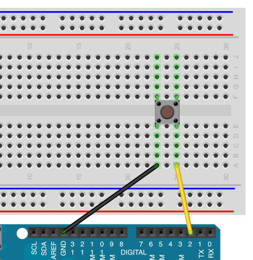
A roughly assembled diagram might look like this:

I will briefly describe this scheme in words. We insert a button in the center of the breadboard so that the breadboard groove runs between the paired legs. Next, connect the power supply with jumpers 5V and land GND on an Arduino with rails on a breadboard. Then we connect the digital pin number 2 on the Arduino with a jumper to one leg of the button on the breadboard. We connect the same leg of the button, but on the other side with a resistor, which plays the role of pull-down resistor. After which we connect the resistor itself to ground. We connect the third leg of the button to the positive rail on the breadboard. All that remains is to connect the side rails together on the breadboard, and we are ready to study a new example.
The button performs a very important function - it closes the circuit when pressed. When the button is not pressed, the current does not pass between the legs of the button, and we cannot catch the signal from digital pin number 2. Therefore, the state of the pin is determined by the system as LOW or 0. When the button is pressed, its two legs are connected, allowing current to flow from the power supply to digital pin 2, and the system reads the passing signal as HIGH or 1.
Let's break down the code piece by piece
// The second pin is associated with the button int pushButton = 2; void setup() ( Serial.begin(9600); pinMode(pushButton, INPUT); ) void loop() ( int buttonState = digitalRead(pushButton); Serial.println(buttonState); delay(1); // delay for stability )
In function setup() We establish communication with the port for reading data at a speed of 9600 bps from Arduino to your computer: Serial.begin(9600).
The second line is already familiar to us, but the parameter is now used here INPUT- we set the second digital output to read data coming from the button: pinMode(pushButton, INPUT);
In the loop we read the incoming information. First we need a new variable buttonState, which will contain the values 0 or 1 coming from the function digitalRead().
So that we can see the incoming information, we need to display the results obtained in the Serial Monitor window using the command println().
For greater stability when reading data, we will set the minimum delay.
If you run the program now and also open the window Serial Monitor(menu Tools | Serial Monitor), then you will see endless zeros on the screen. The program constantly polls the state of our structure and displays the result - no current. If you press the button and hold it, you will see that the numbers change from 0 to 1. This means that current has appeared in our circuit and the information has changed.
02.Digital: Button
Working with a button is also discussed in the example File | Examples | 02.Digital | Button. The button is connected to pin 2, and the LED is connected to pin 13. The button should also be connected to power and ground through a 10K resistor. The principle of operation itself remains unchanged. Only this time we will not display information about the state of the button on the screen, but will turn on the LED. This option is more visual. When you press and release the button, the built-in LED should light up or go out.
Const int buttonPin = 2; // output for the button const int ledPin = 13; // output for LED int buttonState = 0; // button status - pressed or released void setup() ( // output mode for the LED pinMode(ledPin, OUTPUT); // input mode for the button pinMode(buttonPin, INPUT); ) void loop() ( // read the state of the button buttonState = digitalRead(buttonPin); // if the button is pressed, then its state is HIGH: if (buttonState == HIGH) ( // turn on the LED digitalWrite(ledPin, HIGH); ) else ( // otherwise turn off the LED digitalWrite(ledPin, LOW ); ) )
Let's say we want to change the behavior - if the button is not pressed, the LED is lit, and when pressed, the LED is not lit. It's enough to change one line of code.
If (buttonState == LOW)
And now the riddle! You uploaded the first version of the sketch to the board, and suddenly your computer crashed. You cannot edit the sketch to use the second option. How can you get out of this situation?
You need to change the polarity of the circuit! The wire from the resistor that goes to ground needs to be plugged into 5V, and the wire that went from 5V to the button needs to be connected to ground. When turned on, the current will flow from the power supply to pin 2 without any interference and the value will be obtained HIGH. When you press the button, another circuit will be created, and pin 2 will remain without power.
02.Digital: StateChangeDetection
In the example File | Examples | 02.Digital | StateChangeDetection There is a count of button clicks and the state of the button (on or off). The scheme remains the same. The button is connected to pin 2, and the LED is connected to pin 13 (you can use the built-in one). The button should also be connected to power and a 10K pull-down resistor to ground.
Const int buttonPin = 2; // button on pin 2 const int ledPin = 13; // LED on pin 13 int buttonPushCounter = 0; // button press counter int buttonState = 0; // current state of the button int lastButtonState = 0; // previous state of the button void setup() ( // set the input mode for the button pinMode(buttonPin, INPUT); // set the output mode for the LED pinMode(ledPin, OUTPUT); // enable serial data transmission Serial.begin(9600) ; ) void loop() ( // read the readings from the button output buttonState = digitalRead(buttonPin); // compare the state with the previous state if (buttonState != lastButtonState) ( // if the state has changed, increase the counter if (buttonState == HIGH ) ( // if the current state is HIGH, then the button is on buttonPushCounter++; Serial.println("on"); Serial.print("number of button pushes: "); Serial.println(buttonPushCounter); ) else ( // if the current state LOW, means the button is turned off Serial.println("off"); // a small delay to eliminate the bounce effect delay(50) // save the current state as the last state for the next time lastButtonState = buttonState; // turn on the LED when every fourth press, checking the division by the remainder of the press counter if (buttonPushCounter % 4 == 0) ( digitalWrite(ledPin, HIGH); ) else ( digitalWrite(ledPin, LOW); ) )
02.Digital: Debounce
Buttons have such an effect as “blinking”. When closing and opening between the plates of the button, microsparks appear, provoking up to a dozen switches in a few milliseconds. The phenomenon is called bounce. This must be taken into account if it is necessary to record “clicks”. Therefore, primary testimony cannot be trusted. For this reason, there is often a slight delay in sketches, and only then the readings are taken. In the normal state, when we do not press the button or keep the button pressed, there is no bouncing effect. Sometimes for these purposes in educational examples the function is used delay(), but in practice you should use the function millis(), as in the example File | Examples | 02.Digital | Debounce. The connection diagram remains unchanged.
Const int buttonPin = 2; // button on pin 2 const int ledPin = 13; // LED on pin 13 int ledState = HIGH; // current state of the LED int buttonState; // current output state for the button int lastButtonState = LOW; // previous output state for the button // use unsigned type to use large numbers unsigned long lastDebounceTime = 0; // recently unsigned long debounceDelay = 50; // delay, increase if necessary void setup() ( pinMode(buttonPin, INPUT); pinMode(ledPin, OUTPUT); digitalWrite(ledPin, ledState); ) void loop() ( // read the state of the button int reading = digitalRead( buttonPin); // if the button is pressed, // then we wait a little to eliminate bounce // if the state has changed (bounce or press) if (reading != lastButtonState) ( // reset the timer lastDebounceTime = millis(); ) if (( millis() - lastDebounceTime) > debounceDelay) ( // whatever the reading is at, it"s been there for longer than the debounce // delay, so take it as the actual current state: // if the button state has changed if (reading != buttonState) ( buttonState = reading; // switch the LED if the new button state is HIGH if (buttonState == HIGH) ( ledState = !ledState; ) ) // set the LED digitalWrite(ledPin, ledState); the state of the button. Next time in the loop, this will become the value of lastButtonState: lastButtonState = reading; )
02.Digital: DigitalInputPullup (Built-in pull-up resistor)
The digital pins already have 20 kOhm resistors that can be used as pull-ups when working with buttons. Let's look at an example File | Examples | 02.Digital | DigitalInputPullup.
Connection diagram - connect the first pin of the button to pin 2 on the board, and the second pin of the button to pin GND. While the sketch is running, we will read the readings of the second pin.
Void setup() ( Serial.begin(9600); // set pin 2 to input mode and turn on the built-in pull-up resistor pinMode(2, INPUT_PULLUP); pinMode(13, OUTPUT); // LED ) void loop() ( // take the button readings int sensorVal = digitalRead(2); // output to Serial Monitor Serial.println(sensorVal); // Remember that when using a pull-up resistor, the button state is inverted // When not pressed, the button has the value HIGH, and LOW when pressed. // When you press the button, turn on the LED, when you release it, turn it off if (sensorVal == HIGH) ( digitalWrite(13, LOW); ) else ( digitalWrite(13, HIGH); ) )
If we run the sketch, we will see that the numbers 1 are displayed on the monitor ( HIGH). When you press the button, the values will change to 0 ( LOW).
A button is a well-known mechanical device that can close and open an electrical circuit at will. There are many types of buttons that work according to different rules. For example, the push button used in this tutorial only completes the circuit as long as your finger presses on it. An open button, on the other hand, breaks the circuit when pressed.
There are buttons with a group of contacts, some of which break the circuit when pressed, while others close at this time. Small versions of these buttons are often called microswitches.
Tact buttons can be found in almost every electronic device: on a computer keyboard, on a telephone, on a TV remote control, etc.

There are latching buttons that work like a button on a ballpoint pen: pressed once - the circuit is closed, the second time - it breaks. The photo below is just one of these. Locking buttons are convenient to use to switch the operating mode of the device. For example, you can switch the power source: battery or power supply.

Or another option - large buttons for emergency stop of equipment. They are painted in bright colors to attract people's attention. In essence, they are ordinary tact buttons for opening, or buttons with latching.

These are just some of the options. In addition to buttons, there are other mechanisms in the world of electricity, such as toggle switches and switches. All of them are designed to mechanically control the flow of current in the circuit.
Connecting a button
So, we will work with the simplest tact button, which we will try to connect to Arduino Uno. Typically, when working with solderless breadboards, a button with solder pins is used. In the photo at the beginning of the lesson you can see that such a button has four slightly bent pins. There are buttons with two direct outputs, they are also suitable for our activities.
On electrical diagrams the button is depicted like this:
![]()
If you look inside the four-stroke button, you can see this diagram:

As a rule, the pins of the tact button are placed on opposite sides of the case in pairs. That is, we can use either a pair of contacts on one side or a pair on the other.
And this is what the diagram of a two-pin button looks like.

It's hard to get confused with this button: two contacts that connect when you press the button.
On a breadboard, both types of tact buttons are usually placed as follows:

Now let's try to assemble the simplest circuit on a solderless breadboard that will demonstrate the operation of the button. We will light the LED.

The resulting circuit performs a simple function: press the button - the LED lights up, release it - it goes out.
Connection to Arduino Uno
Now that the function of the tact button is extremely clear, let's assemble a circuit with a button and an LED, and connect them to the controller. Let's set ourselves a simple task: let the Arduino Uno LED blink three times when you press the Arduino Uno button once.
Schematic diagram

Layout appearance

In this diagram we see the already familiar circuit for. We also see a button connected to Arduino pin No. 3. Here a question may quite reasonably arise: why did we also connect the button to ground, through a 10 kOhm resistor? To deal with this issue, let’s imagine that we connected the button using a “naive” circuit without any additional resistors.

Here, between pin No. 3 and ground, there is a small capacitor that can accumulate charge. Many microcontrollers have this feature.
Now imagine that we are closing the button. The current starts running from +5V, straight to contact No. 3, simultaneously charging the capacity. The Arduino successfully registers the button press. But after we remove our finger from the clock button, contrary to our expectations, the microcontroller continues to consider that the button is pressed! Of course, because a charged capacitor gradually releases the accumulated charge to leg No. 3. This will continue until the capacitance is discharged below the logic one level.
Connecting the ROC clock button module to Arduino
Especially for your projects, we at RobotClass have made a module of two tact buttons. The module already has the necessary resistors and even two LEDs to indicate button presses.

Let's figure out how to connect this module to Arduino Uno.
Schematic diagram

Layout appearance

As you can see, no matter what buttons we use, the connection diagram does not change much. The program for working with them will not change either.
Program for working with a button on Arduino
Finally, we have figured out the nuances of our scheme, and are ready to write a program. In the software tutorial, we learned about the pin configuration functions pinMode and digital output function digitalWrite. This time we need one more important function that provides information input to the microcontroller:
DigitalRead(contact_number);
This function returns the Boolean value that Arduino read from a given pin. This means that if +5V is applied to the contact, the function will return truth*. If the contact is connected to ground, we get the value lie. In C++, true and false are equivalent to the numbers 1 and 0, respectively.
In order for the contact we are interested in to work in information input mode, we will need to set it to a certain mode:
PinMode(pin_number, INPUT);
Finally, let's put everything together and write a program.
Const int led = 2;
const int button = 3;
int val = 0;
void setup())(
pinMode(led, OUTPUT);
pinMode(button, INPUT);
}
void loop()
val = digitalRead(button);
if(val == HIGH)(
// loop from 0 to 2, in steps of 1
for(int i=0; i<3; i++){
digitalWrite(led, HIGH);
delay(500);
digitalWrite(led, LOW);
delay(500);
}
}
}
We load the program onto the Arduino Uno and check the operation of the program. If everything is done correctly, it should look like in the picture:
OK it's all over Now. Now we can control our devices using buttons. If you have already completed the lesson on, then we will be able to make a clock with an alarm clock!
Trigger button program
Another example worth noting is the trigger button. It works like this: press the button once - the LED lights up, press it a second time - it goes out.
To implement this button behavior, we need an additional variable, often called a “state variable” or “flag”.
Const int led = 2;
const int button = 3;
int val = 0;
byte state = 0; // state variable
void setup())(
pinMode(led, OUTPUT);
pinMode(button, INPUT);
}
void loop()
// write the button state to the val variable
val = digitalRead(button);
// if the button state is true, perform the action
if(val == HIGH)(
// change the state to the opposite
state = !state;
if(state == HIGH)(
// if the current state is true, light the LED
digitalWrite(led, HIGH);
) else (
// if the current state is false, turn off the LED
digitalWrite(led, LOW);
}
delay(300);
}
}
We load the program onto Arduino and check the operation of the circuit. Quickly press the button and the LED will light up. Press again and it will go out. But if you press the button and do not release it, the LED will start blinking with a period of 600ms! Why is that? Try to figure it out.
Tasks
As a practice, let's try to solve a few simple problems with a button and an LED.
- The circuit contains two buttons and one LED. Let the LED light up when you press the first button, and go out when you press the second button.
- Piano. The circuit contains seven buttons and one speaker. When you press each of the seven buttons, the speaker should play the corresponding note. Will need to study.
- Game "Cowboys". The circuit contains two buttons, one buzzer and two LEDs. After the program starts, the buzzer should make a short sound. Immediately after this, each player must press their button as quickly as possible. The player who does this first will have an LED light. You will need to study the lesson about interruptions.