In this tutorial, we will cover the basic principles of setting up lights for interior lighting and creating a global illumination effect in Mental Ray. We will also look at some of the problems that can arise when illuminating a textured scene, and how to solve them.
To complete the lesson, we first need to create a room.
In the projection window Top create a spline Rectangle. Select it and go to the tab Modify command panel. Select a modifier from the list of modifiers Edit Spline. In a scroll Selection click on the button Spline(the red curve is like this) and then in the scroll geometry click on the button outline and in the window Top move the spline outward a bit. Now again from the list of modifiers select extrude and extrude a 3D object of suitable height from the spline. These will be the walls.
Now make a floor and a ceiling from a regular plane.
Next, cut out the window. Create box. Position it in the wall so that all corners stick out of the wall. Select it and in the category drop-down list geometry tabs Create command bar select line Compound Objects. Click the button Boolean, then, in the rollout that appears, click the button Pick Operand B. Select a wall object in any window. Set the operation type to B-A. The window is ready, just like the stage itself. Although no! Add a couple more beauty objects to the room. It will be something like furniture. Put the ceiling on the walls and everything else with the usual standard gray material.
Position the camera indoors and focus properly.
Point a light source at the window mr Area Spot.

Adjust the light source. When working with photons, the parameter hot spot in a scroll Spotlights Parameters light source. These parameters should be adjusted as precisely as possible to the size of the window through which light enters the room in order to avoid the loss of photons, the maximum number of which depends on the size of your PC's RAM. Since the window is rectangular, then you need to specify the shape Rectangle and adjust the cone to fit the window. To make it easier to change the direction and taper, switch one of the windows to view from the light source. In a scroll Area Light Parameters check the box On and specify the type of scattered light Disc with a scattering radius of 40. Although, you can set a much larger value. I have never seen the sharp outline of a window opening in the shadows when no sunlight enters the window. From this we can draw conclusions. If you want the sun's rays to fall through the window in your scene, then setting blurry shadows will be a big mistake. Another situation is when the light of heaven.
With the creation of the scene like everything. Submit the scene for rendering. Dark isn't it? It's time to deal with global illumination in Mental Ray. Opening the window Render Scene, select as a visualizer mental ray. Go to tab Indirect illumination and in the scroll Caustic and global illumination in the GI block, check the box enable. Render the scene. Virtually nothing has changed. Not without fine tuning.
So, let's start setting up the lighting of our test scene. Set value Maximum Sampling Radius equal 4 . The Radius value is the photon search radius. It is the photon search radius, not the size of the photon! Photons have no size in terms of computer graphics. The absence of the Radius checkbox means that the photon search radius is approximately 110 parts of the scene. Maximum Num value. Photons is the number of samples for calculating the illumination of a point. Meaning Average GI Photons set equal to 10 000 . As you already understood, the GI Photons value determines the number of photons from the light sources, it is this number of photons that is stored in the photon map. The Decay value determines the attenuation with distance, a value of 2 is considered physically correct. The Global Energy Multiplier value is a kind of regulator with which you can control the overall illumination of the scene.

The Trace Depth value sets the level of reflection and refraction of surfaces in the scene. Photon Map - installation of a photon map. Please note that some parameter values in the result may differ depending on the coordinate system. This applies to all parameters that specify dimensions, distances, radius, etc. We consider all values in Inches, not in millimeters or meters, etc.
Render the scene again.

Bright spots of light with a radius of 4 indicate that photons are being generated, that the photon search radius is 4 inches, and the presence of large unlit black areas in the scene indicates that there are not enough photons for this scene. Change the number of photons from 10,000 to 500,000.

Already better, but still dark and there is noise. There are two ways to get rid of the noise and make the lighting more intense. To reduce noise, you can further increase the value of Average GI Photons, but this will lead to an increase in rendering time, and you will not achieve excellent results. The Average GI Photons values are limited by the PC memory and you cannot use very large values. The second option is to increase the photon search radius, which will smooth the picture. But then the secondary shadows will be calculated ugly, which will look completely unnatural. The best option is to adjust these values so that there is no noise and the shadows are normal. Here is a good image.

Here I used Average GI Photons = 1500000, Maximum Sampling Radius = 13, and Global Energy Multiplier = 6500. In fact, the picture is still terrible. Lights appeared due to too high Multiplier value. This can often be seen in galleries, when window sills, window frames and, sometimes, ceilings are highlighted in interior images. It is not right!
Despite the fact that the photon map method gives the most physically accurate results of scene illumination, the number of photons to obtain high-quality illumination with a minimum photon search radius should be too large. Modern PCs and a 32-bit operating system will not allow you to calculate such a number of photons.
The most realistic competent lighting in interiors gives the combined use of photons and Final Gather. What does it represent Final Gather? A hemisphere of unit radius is constructed above the point, and rays are emitted through the surface of the hemisphere in random directions. The more such rays, the more accurate the calculation and the less noise. In practice, the number of rays is the number of samples in Final Gather. For each ray, the intersection with the nearest surface is found. The beam is being processed. There is no further ray tracing. Final Gather ray tracing depth is always set to one. I recommend using only one Final Gather in scenes using HDRI maps in the global environment or exteriors.
And so we turn on Final Gather and set the values as shown. But first return the values Average GI Photons = 10000.

Checkbox preview serves for fast rendering in low quality. Render the scene.

As you can see, there is noise, but not the same as when Final Gather is disabled. Just increase the value Average GI Photons before 200000 And samples in Final Gather with 50 on the 500 , and get a very acceptable picture.

Apply textures. I used standard materials and Max's bitmaps (*.jpg). Render the scene again.

Not a very pleasant sight? Here! Now is the time to talk about the problems that can arise when using Mental Ray GI. As you have already noticed, the scene has a rather strong color transfer from the walls and floor to the ceiling, and indeed to each other. This effect is called . You can deal with this in different ways. For example, controlling color bleeding with photon shaders. But I think the best option is the following. We calculate the photon map and Final Gather in the scene with gray material, as in Figure 9, and save it to a file. Next, we assign the necessary materials to the scene objects and render by loading photons and Final Gather from the file. To be honest, I don't understand why the developers didn't make the color bleeding option like in finalRender, for example.
Let's finish the job. Here is a picture rendered in this way.

For the sake of example, I threw a couple of models of chairs with a carpet and one wall into the scene. I am not an interior designer and this is not a competitive entry, so please do not criticize me for such an incomprehensible attempt at arranging furniture.

A good picture without glare on the window and with uniform illumination and with only one light source. Some might argue that the stage is a bit dark. Stop! And where did you see in reality a well-lit room through such a small window? Do not overdo it with the intensity of light. This is where the highlights appear, and the scene looks unrealistic. A well-lit scene is when it is not bright and without highlights, when all objects and angles in the camera's field of view are clearly distinguishable. To correctly illuminate the scene, use the SkyLight light source.
Finally, I want to give some tips that will help you avoid mistakes in your work with Mental Ray.
1. Never make walls, floors and ceilings with zero thickness! Mental Ray will simply ignore the rotated wall normals and let light into the room as if it were open space. This is also true for other renderers.
2. Use the SkyLight light source for illumination. To add light, realism and highlight the places of window openings that are in the shadow area, SkyLight is best suited. In large interiors with many windows, instead of skylight in window openings, you can use a photometric light source - TargetArea.
3. I recommend using only "native" materials in all external renderers. This applies to a lesser extent to Mental Ray because both standard and ray tracer and architectural materials work quite well in Mental Ray. But, despite this, only the use of "native" materials, which include DGS material, mental ray, Glass (physics_phen) and Lume shaders, gives the most physically accurate correct results. When using (in interior scenes using photon maps) a mental ray material in the Photon slot, you must definitely use a photon shader. When used in the Surface slot - DGS materiala, in the Photon slot it is better to use DGS material Photon. When using Lume shaders in the Surface slot, for example, Metal(lume) in the Photon slot, it is better to use Photon Basic.
4. Photon rendering, Final Gather, and rendering progress can be monitored visually by enabling the Mental Ray Message Window.
5. Adjust the lighting in the scene by assigning a gray material to all objects. Remember that textures and materials tend to hide GI imperfections. And only after you find the optimal GI settings in the scene, assign materials to objects, adjusting the materials to the lighting, and not vice versa. Remember also that in Mental Ray photon shaders have a direct effect on the lighting in the scene, and if you want them not to affect the overall lighting set up in the scene with gray material, set the photon shaders to the same parameters that they had when setting up lighting in a scene. Now let's talk about radii in Final Gather. Max Radius is the distance between points for which GI (Global Illumination) is calculated. The smaller the distance between the points, the more accurate the calculation and the more time it will take. Min Radius is the distance used in the interpolations and extrapolations of the illumination of intermediate points. In practice, to get normal quality GI Min Radius should be 10 times less than Max Radius. Increasing the values of the radii leads to a decrease in the quality of the secondary shadows, a decrease leads to a more accurate calculation of GI and, as a result, an increase in the rendering time. The smaller the radii, the more samples you have to put in Final Gather. The number of samples required for smoothing, with the above values of the radii ranges from 500 to 3000 depending on the scene. The bigger, the better. But do not get carried away by increasing this value, as the rendering time will increase greatly.
Hi all. My name is Maxim Ganzha, today, after numerous requests from my friends, I decided to write a short article about how I create my interiors. Let's consider all of us on one of the latest works with crazy lighting and awesome composition =), which I did in MentalRay.
"Livingroom"
Have you ever wondered why some works are more interesting on the forums than others? I'll tell you a little secret. It's all about beautiful lighting and strong composition. We will talk about this, as well as many other things, in this article. =)
I think we will skip the modeling process otherwise the article will be very long and boring. So let's go!
1. Setting up and setting up lighting.
In order to get started, first of all, you need to open the scene, and select the Mental ray renderer from the list of available renderers.
We open the stage.

Go to render settings F10, in the "Assign renderer" tab, click the "Choose renderer" button and select Mental Ray.

Once we have selected a render, mental ray shaders and materials will become available in the material and map browser. Select the Material "Arch & Design" and adjust the following RGB diffuse color around 0.8 0.8 0.8 other settings in the screenshot. I would also like to note that you should not forget to include "AO" in the materials. With this setting, the shadows will look more realistic. and the darkening characteristic of real light will appear in the corners. "Max Distance" always put about 3 meters (distance from floor to ceiling).

Open the render settings, In the "Translator Options" tab, enable the Eneble checkbox on Material Override and throw our prepared gray material into the slot. This will ensure that all objects in the scene are painted with the same material. This will make it easier for you and your computer to adjust the lighting. Rendering will be fast and not time consuming. We will look at the materials of all objects in the scene later.

After assigning a gray material to all objects, we need to create a "Daylight System"

create and place the sun It's okay if it shines in the other direction. go to the system settings and, as shown in the figure below, check the "Manual" box, after which we can set the sun as we please without setting the time and date. Place the sun as shown in the picture.

During the creation of the daylight system, 3ds max will offer us to put "mrSky" as the environment, we agree and move on.

after we have installed the daylighting system, we take up the windows. You need to put "mr Sky Portal" in them, it is located next to the photometric lamps.

press the button and set as shown in the figure below.


as you noticed the portal is directed by the arrow in the wrong direction. We need the arrow to point into the room. To do this, simply click the Flip Light Flux Direction checkbox. And everything will fall into place as in the figure below. =)

we select our portal, hold down the "Shift" key and move it to the left to the second window. 3ds max will offer us a copy type. Select "Instance"

Finally put the daylight. Now we just need to set it up. Press "F10" turn on Final Gather (FG) Global and Illumination (GI). The settings are shown below. I just turned on the FG & GI checkboxes and lowered the quality of the FG Precision Preset.

We set the image resolution to 450 by 338 and make a test render.

Press the 8 key and in the "Environment" settings in the "Exposure Control" tab, set "mr Photographic Exposure Control".

Press render and see what we got =)

This render has the following exposure settings:
As you can see, nothing remarkable happened. The light is dim and ugly. In order to make beautiful lighting, we will have to twist the exposure control a little. Then I remembered that I wanted to use artificial light. Turn on the floor lamp next to the sofa. The sun would obviously interfere with this and I turned it off. We go into the settings of the Daylighting System and uncheck the "On" checkbox in the "mr Sun Basic Parameters" tab.

Now press the "8" key again and set the exposure control as shown in the figure below.

And here's what we got.

Well, that's a completely different matter. The light became like daylight. =)
Now let's start setting up the lighting of the floor lamp. In artificial lighting, I like to use photometric fixtures. Choose this lamp:

And put the bulbs in place in the floor lamp as shown in the figures below.


in the settings of the lamp, turn on the shadows "Ray Traced Shadows" In the "Shape/Area Shadows" tab, set the disk with a radius of 30 mm. Turn on the "Light Shape Visible Rendering" checkbox and set 64 samples. These settings will allow us to achieve beautiful realistic shadows from the lamp.


let's see what happened.

We see that the light from the lamp turned out to be white. And I would like to make it more like a simple light bulb. To do this, we need to lower the temperature of the light. We also see that the light is too intense. With such a shutter speed of the camera and such daylight, it should be practically invisible. and he is like a spotlight. =)
Open the settings of the photometric lamp again and adjust the temperature with intensity.

Let's see what happened:


That's what we need. Perfect light! I don't know about you, but I really like it. Yes, and whoever plays orange light with blue is a win-win option in architectural visualization. =)
I would like to add some special effects. To do this, go to the render settings, and in the "Camera Effects" tab, turn on the "Output" checkbox DefaultOutputShader (Glare) take the shader with the mouse and throw it in the "Material Editor", after that 3ds max will offer us the copy type, We put "Instance" click " ok".

Behind the windows, as in the figure below, we put the "plan" object, which will play the role of a background for us.

in the settings of the "plan" object, turn off the checkboxes as follows.

And assign it the material "Arch & Design"

Once again, press the render button and see what we got. =) For a quick rendering, I assigned a gray material to all objects except the background.

Well, here we have a good picture. A slight haze from the glow effect gives the picture a lively atmosphere. You can stop with the render settings and start looking at the materials.
2. Customization of materials.
It's time to break down the most basic materials that I used in this scene. Let's start with the most interesting.
Carpet.
As you can see from the grid, the geometry is very simple.

the carpet used a simple material "Arch & Design" with the following parameters:
Diffusion map.


"Displacement" used the following texture.


Sofa.
The mesh of the sofa is quite complex. On this model I used two materials. Fabric and wood legs.

Let's look at the fabric material first.

in the diffuse slot we throw the shader "Ambient / Reflective Occlussion" and in it we place two fabric textures of the same type. The only difference is that one is darker than the other. The settings are in the picture below.

the following parameters are ambient ok and bump.

now wooden legs.

In diffuse I used a simple parquet map. The settings are in the picture below.

bump settings.

Coffee table.
The material and mesh of the coffee table is as follows.


everything is simple with glass, select the material "Arch & Design" and select the finished material in it as shown in the figure below.

Magazines.
I wanted to make "Arch & Design" a glossy magazine, I didn't really bother with material settings. Therefore, I used a simple glossy plastic.

magazine grid.

settings look like this.

I colored the pages with the same material, only with white in the Diffuse color.
Newspaper.
The magazine rack itself is made of lacquered wood. Decided to color it with "ProMaterials" Hardwood.

Newspaper grid.

Promaterial Hardwood settings.

I also used the second material to color the newspapers themselves and made it matte.

newspaper material settings.

Flower.
At this stage, I used the same, my favorite material "Arch & Design". 

You can see the settings in the pictures below.


Curtains.
I had to experiment a little with curtains. And finally, I came to this option.

Mesh curtains.

In the diffuse as shown in the image below, I naturally used the fabric texture. Also, do not forget about the AO parameter. =)


Walls.
The walls were made of old plaster, which was later painted with paint. And that's what I got, again my favorite "Arch & Design".

The map looks like this on the wall.

Reflection settings look like this. 

Parquet material (floor covering).

Settings.


Floor lamp.
On the floor lamp, I used three materials. These are a lampshade (fabric material), a rack (metal material) and an electric wire (plastic material).

let's start with my favorite material "Arch & Design" is the fabric on the lampshade of the floor lamp.

He's pretty simple. Diffuse color, slight transparency and bump. We will see this in the settings in the pictures below.


To make the metal material of the rack, I used ProMaterials: Metal.


Floor lamp plastic wiring material ProMaterials: Plastic/Vinyl


I would also like to advise you one resource that is directly related to Mental Ray materials. He helped me many times. Thanks to those who founded the site. http://www.mrmaterials.com/
That's probably all, with the materials finished. Now we can discuss composition.
3. Final render settings.
It's time to increase the render settings and make the final render. You can see the settings in the picture below.


Turn on render and wait =)
4. Composition.
There are 10 composition rules worth learning.
1. Contrast.

ms_Dessi
How to draw the viewer's attention to your render? There should be contrast in the frame: A lighter object is shot against a dark background, and a dark one against a light one.
2. Accommodation.

Morro
Important plot elements should not be randomly placed. It is better that they form simple geometric shapes.
3. Balance.
Objects located in different parts of the frame must match each other in volume, size and tone.
4. Golden section.

The golden ratio was known in ancient Egypt, its properties were studied by Euclid and Leonardo da Vinci. The simplest description of the golden ratio is that the best point for the location of the subject is about 1/3 of the horizontal or vertical border of the frame. The location of important objects in these visual points looks natural and attracts the viewer's attention.
5. Diagonals.

FeodorIvaneev

FeodorIvaneev
One of the most effective compositional techniques is diagonal composition. Its essence is very simple: we place the main objects of the frame along the diagonal of the frame. For example, from the top left corner of the frame to the bottom right. This technique is good because such a composition continuously leads the viewer's eye through the whole picture.
6. Frame format.

Morro

FeodorIvaneev
If the render is dominated by vertical objects, use the vertical frame format. If the objects are horizontal, take horizontal shots.
7. Shooting point.

FeodorIvaneev
The choice of shooting point directly affects the emotional perception of the picture. Let's remember a few simple rules: For character rendering, the best point is at eye level. For a full-length portrait - at waist level. Try to crop the frame so that the horizon line does not divide the photo in half. Otherwise, it will be difficult for the viewer to focus on the objects in the frame. Adjust the camera angle at the object level, otherwise you risk getting distorted proportions. When viewed from above, an object appears smaller than it really is. So, drawing a character from the top point, on the render you will get a character of small stature.

Dmitry Schuka
Our brain is used to reading from left to right, so we also evaluate the picture. Therefore, the semantic center is better placed on the right side of the frame. Thus, the eye and the subject seem to be moving towards each other. When building a composition, always keep this in mind.
9. Color spot.

If there is a spot of color in one part of the frame, then there must be something in the other that will attract the attention of the viewer. This may be another color spot or, for example, an action in the frame.
10. Movement in the frame.

Alexander1
If you decide to draw a moving object (car, cyclist), always leave free space in front of the object. Simply put, position the subject as if it had just "entered" the frame, not "left" it.
Perhaps we will focus on the composition and proceed to the post-processing of the render.
5. Post processing.
Now it's time to do a little post-processing on the resulting image. Usually I always resort to this in my daily work. Since some things are still easier to achieve in Photoshop than by means of rendering. So what do we have =)

If you look closely, the possibilities of Mental Ray are very wide, the picture practically does not require effects. But it's still worth adding a few lens effects. To get the feeling of a real photo.
It seemed to me that the picture lacks the effect of a blue glow around the windows, so we open our renderer in the excellent program "Fusion" and apply a glow effect to the existing image. Speaking in common, we cling to it the "SoftGlow" node

click the polygon and draw a window as shown in the figure below. Thus, we drew a mask in fusion on which the glow effect will be applied.


now click on the SoftGlow node and configure as follows.

we will have a pleasant glow at the windows.

add the SoftGlow node again and apply the effect to the whole picture. Set it up as follows so that the whole picture has a slight blue glow.

turn off the checkboxes Red, Green and Alpha and move the Gain slider a little to the right. The picture below shows both options. Left before, right after applying the effect.


Close Fusion and open the image in Photoshop.

In Photoshop we open the image with the Magic Bullet Photo Looks plugin... and apply the Anamorphic Flare effect with the following settings

there was a very beautiful glow characteristic of a real camera. Next, apply the Vignette effect and add a slight darkening around the edge of the image. The settings are also shown in the lower right corner.

Adding a very interesting effect called Shutter Streak adds small rays to the top and bottom of our image.

now my favorite step =)
Add the Chromatic Aberration effect and set it up as shown in the image below.

at a high resolution of the picture, it will almost not be visible, but it will add realism to the picture.
Click the button

and save the picture.
That's what I did.

So my lesson has come to an end, I want to wish you all good luck and fast renderings. Always your Maxim Ganzha.
Lesson taken from 3dmaks.com
Global Illumination ( GlobalIllumination, GI) allows you to simulate the effect of surface scattering of light, which is observed as a result of the reflection of the light propagated by a source from a variety of surfaces. An example of such lighting is the sunlight falling through the window, which is reflected from the floor and illuminates the entire room. When rendering with standard means, only the floor will be illuminated in such a scene, and when rendering in Mental Ray, walls with a ceiling can also be illuminated (what exactly and to what extent depends on the location of the window and the intensity of the light). The global illumination effect is implemented in two ways: using the function GlobalIllumination(global illumination) or by connecting method FinalGather(final fee). In both cases, the rendering process is quite lengthy and is even longer if both methods are involved, but this is often done, since the combination of both methods allows you to get more impressive results.
Using GlobalIllumination photons are emitted from the light source, and the renderer (just like when simulating the caustic effect) tracks their distribution in the scene and sums up the energy of all photons at each point in space. Method FinalGather works differently, although its purpose is the same as GlobalIllumination: after the first ray hits a point on the surface of an object, an additional beam of rays is emitted from this point into the scene, with the help of which information about the color around this point is collected, on the basis of which the scene illumination is calculated. Such a miscalculation requires about more time than using GlobalIllumination, but this produces smoother highlights and shadows. In addition, the application of the method FinalGather It also turns out to be useful in simulating the effect of caustics, since it makes it possible to reduce or even eliminate the artifacts that occur in some cases.
For example, create a new scene with a plane, a ball and a teapot (fig. 20). Set up one directional light source, place it on the left side of the scene and turn on shadow generation for the source by type RaytracedShadows(Fig. 21). Create a glowing shader-based material architectural by changing the color in the box diffusecolor and increasing the parameter value Luminancecd/m2, responsible for the glow level, up to about 7000 (Fig. 22). Make the ball glow by assigning the created material to it. Render with the Scanline renderer - despite the fact that the ball glows, the light from it does not spread anywhere, which in reality cannot be (Fig. 23).


Set Mental Ray as the current renderer. Enable Global Illumination Simulation: Activate in Window RenderScene tab IndirectIllumination and in the section FinalGather enable checkbox enableFinalGather. Render the scene again, and you will see that the light from the ball now illuminates the space of the plane below it a little (Fig. 24). Increase the parameter value multiplier up to 1.5, and RaysperFGpoint up to 500 - the intensity of the light propagating from the ball will noticeably increase (now reflections of scattered light are visible not only on the plane, but also on the teapot) - fig. 25. In addition, the image quality has become noticeably higher, which was achieved by increasing the value of the parameter RaysperFGpoint, which controls the number of light rays in each beam.


Let's complicate the task. Create a new scene with a closed linear spline in the form of a rectangle (it should be formed in the projection window Top) and a kettle inside. Give the spline a modifier extrude, which will make it possible to turn it into a kind of closed cubic space - an imitation of a room, inside which the teapot will be (Fig. 26). Add a camera to the scene so that it can see the space inside the room and place a flat cube on the ceiling of the room (in our case, it will play the role of a lamp operating in night light mode) - fig. 27.


Assign a luminous material to the lamp and texture the walls, floor and ceiling of the room if desired, and then render the scene with standard tools (Fig. 28). Set Mental Ray as the current renderer and enable simulated global illumination by checking the box enableFinalGather. Increase the light intensity by setting the parameter multiplier equal to 1.7, and to speed up the rendering process, reduce the value of the parameter RaysperFGpoint up to 50. Render through Mental Ray (Fig. 29). Obviously, in both options (Scanline and Mental Ray), the lighting turned out to be completely unnatural. According to the plan, a lamp on the ceiling should illuminate the space. In the first version, no glow from it is visible and at the same time the walls of the room are illuminated, although no light sources were created. At the same time, the kettle seems to float in the air, which is a consequence of the absence of shadows. In the second case, the lamp illuminates the space with diffused light, a shadow appeared under the teapot, but the walls of the room are still unnaturally lit - the presence of another light source is felt. It is clear that this source is set by default (after all, we did not create sources), but in this example it turns out to be superfluous. To get rid of it (you can't delete it, because the source does not appear in the list of objects in the scene), create your own light source (after that, lighting is turned off by default) and block it by deselecting the checkbox On in the region of lighttype section GenerelParameters(Fig. 30).


If we now immediately render, then practically nothing will be visible in the room (Fig. 31). So increase the parameter value RaysperFGpoint up to 500 - the illumination will increase slightly (although the walls will still not be visible) due to an increase in the number of scattered rays (Fig. 32). Set parameter diffuseBounces set to 4, which will ensure the appearance of chiaroscuro on the floor, walls and ceiling (with further increase in this parameter, the shadows become lighter), and multiplier- 2.2, which will increase the light intensity (Fig. 33). Once again increase the number and also the density of scattered rays by setting the parameters RaysperFGpoint And InitialFGpointDensity equal to 700 and 1.5, respectively (Fig. 34), the image obtained during visualization will turn out to be of better quality, although it is still somehow ghostly (it seems that some kind of haze is hanging in the air - Fig. 35).


Rice. 34. Customizing Scroll Options Final Gather

Now let's see what results can be obtained using the method GlobalIllumination (GI). In section FinalGather turn off the checkbox enableFinalGather, and in the section GlobalIllumination (GI) enable checkbox enable and render. The results will be disappointing (Fig. 36), since the method GlobalIllumination is based on the emission of photons by the light source, and the only source in the scene is blocked. Unblock the source, move it inside the lamp, reduce the intensity of the source to about 0.3 and change the hue to close to the hue of the luminous material (Fig. 37). Turn on shadow generation by type for the source RaytracedShadows and visualize the scene - the room will be illuminated, but will be illuminated evenly (without chiaroscuro) and no glow from the lamp will be felt (Fig. 38).


Let's try to experiment with the global illumination settings. First, increase the energy of photons and the number of them that takes part in Global Illumination by selecting the source and increasing it in the scroll mentalray: IndirectIllumination parameter values Energy And GIPhotons up to 10 and 400, respectively (Fig. 39). As can be seen from the result (Fig. 40), the increase in energy was excessive (decrease Energy to 5), the size of photons and their intensity are clearly insufficient, as well as their number. At the same time, realistic, soft chiaroscuro can be obtained only with a very large number of photons of an acceptable size (for a small photon radius, setting an arbitrarily large value for the number of samples has practically no effect on the result) and intensity. Try setting the parameter values multiplier, MaximumNumPhotonspersample And MaximumSamplingRadius equal to 1.2; 1500 and 14, respectively (Fig. 41). The result has improved markedly (chiaroscuro on the walls, floor and ceiling are quite natural) - fig. 42 but no connection method FinalGather I can't get the lamp to glow.
Current page: 25 (the book has a total of 31 pages) [available reading excerpt: 21 pages]
Font:
100% +
Lighting and setting up light sources
The scene is fully textured, the cameras are installed to obtain suitable rendered images of the interior. The turn has come to build the correct lighting of the scene and add certain visualization effects, with the help of which the images of the scene will become more spectacular and realistic.
It has been noticed that only a well-lit space allows you to get a certain impression from the built-up scene. Usually, for beginners, the correct installation and adjustment of the scene illumination presents some difficulties, since it is with the help of light that the surrounding space opens up for a person. After all, the colors of objects, the properties of surfaces, and everything else that a person sees in the world around him, is nothing more than a reflection from the surface of an object of light directed at it from different angles. Getting on the surface, the light is scattered, and the composition of its frequency spectrum changes (depending on the reflective properties of the object). The conclusion follows from the above: with the help of the correct adjustment of the textural qualities of objects and lighting, you can both improve the impression of a mediocre scene, and, conversely, spoil a well-prepared visualization.
Physical representation of lightFrom the point of view of physics, light radiation is characterized by the concepts of luminous flux, luminous intensity and illumination. Light flow sets the energy of light emitted per unit of time and is measured in lumens (lm, lm). The luminous flux emitted within a given region of space is called by the power of light and is measured in candelas (cd, cd). The luminous intensity characteristic makes it possible to compare sources with different spatial distributions of light. Illumination - this is the ratio of the luminous flux to the area of the illuminated surface, measured in lux (lx, lx).
In addition to the above lighting characteristics, color temperature and the location of light sources are very important for 3D graphics. Under color temperature refers to a physical quantity that characterizes the magnitude of the color and brightness of a light source, measured in kelvins (K). Hues with a temperature below 4000 K are considered warm (colors from red to yellow - the color of a candle, incandescent lamps, etc.), and sources with a color temperature above this are considered cold. Fluorescent lights, strobe lights are examples of cold light sources. With the help of color temperature, you can change the feeling of a person when viewing a scene (a similar technique is often used in cinema and photography).
Types of Lights in 3ds Max 2009In the previous version, mr Sky Portal (Mental Ray Sky Portal) was added to the light sources. This illuminator makes it easy to set up daylight lighting in interior scenes, its operation is similar to lighting based on HDRI effects. If you take into account Mental Ray light sources, then by default the program provides twelve different types of scene illuminators and a system of objects Sunlight (Sunlight) and Daylight (Daylight). There are several software and hardware lighting algorithms in it, each of which has its own settings and lighting settings.
Standard illuminators - without taking into account the reflected light from the surface of objects.
Photometric illuminators - calculation of global illumination and diffuse scattering.
Built-in Mental Ray external renderer with its own light source objects.
In addition, it is possible to connect other render modules, each of which, as a rule, provides its own illuminators for use.
Starting from the sixth version, the program has another way of lighting - using HDRI (High Dynamic Range Image - an image with an extended dynamic range). One way to use HDRI is described later in this chapter.
In each case, the choice of lighting method is determined by comparing the results of applying several methods, which are evaluated according to criteria such as photorealism and rendering time. If, for example, a photorealistic rendering of a scene lasts 5–6 hours, then animating such a scene is quite problematic due to too much time. But as a sketch of the interior, the image obtained in this way will be the most suitable. However, there are still no clear criteria for choosing one or another method. Having applied the above methods several times and seeing the difference between them, you can understand which method of setting up the scene lighting is more suitable for you in this or that case. True, in any case, when using any methods of installing lighting, a fairly careful setting of the parameters is required, and, perhaps, a good result will not be obtained immediately.
Default lightingIf you do not include any lights in the scene, 3ds Max 2009 will automatically set the scene to default lighting. It is a built-in (omnidirectional) standard light sources with parameters that cannot be adjusted. There can be one (default) or two built-in sources. A single source gives a contrasting, not very natural light (Fig. 5.15). Two built-in lights are located: one in the upper left corner of the scene in front, and the other in the back in the lower right corner. You can change the default lighting settings using the Views → Viewport Configuration menu command. A tabbed window will open, from which you need to select Rendering Method (Rendering Method) and in the Rendering Options area (Rendering Options) change the desired settings. Lighting with two built-in sources is softer and more natural than one. These sources do not form shadows from objects, and rendering with them does not look natural, but they allow you to see the location of objects in the scene. The previous chapter described exercises in which the rendering was done using only the default lighting. If at least one light source is installed in the scene, the lighting is automatically turned off by default and further illumination is determined only by the presence and power of the installed illuminators.
Rice. 5.15. Scene lighting by default with one source
If you do not check the Default Lighting checkbox in the default lighting settings, then in the viewports the scene will be illuminated by the established sources, which is not always good for clear visibility of objects. Therefore, it is better to check the box before starting work with light sources.
In addition, the illumination of the scene also depends on the ambient illumination, which does not have a source and is controlled by changing the overall illumination level in three color parameters. The setting is carried out using the menu command Rendering → Environment (Rendering → Environment). A dialog box opens with two tabs, from which you need to select Environment (Environment) (Fig. 5.16). Thus, both the level of influence of the ambient illumination on the illumination of the scene and its color are established, as well as the possibility of using the image as an environment map. It is better to refuse to use a large level of general illumination (Ambient) in the scene, and it is worth increasing it only if necessary and only by a small amount. This is necessary because the general illumination makes objects flat, erases their edges.

Rice. 5.16. Scene environment settings
Standard illuminatorsThere are seven standard illuminators in the program, not counting Mental Ray illuminators (Fig. 5.17). The set of standard sources is sufficient to simulate relatively realistic lighting from both artificial and natural light sources.

Rice. 5.17. 3ds Max 2009 Standard Lights
Now about each source in more detail.
Source Sunlight (Light of the sun) is designed to create and manage an imitation of sunlight in the scene. This object can be found by clicking the Systems button on the Create tab of the command bar. When it is used, a directional light source is created that illuminates the scene at an angle of imitation of the sun's rays falling on the Earth's surface at given geographic coordinates and at a given time. It is a legacy of older versions of the program and was left in 3ds Max 2009 mainly for project compatibility. Starting with the fifth version, it is replaced by an improved Daylight system (Daylight).
Omni (Omnidirectional source) - emits light rays in all directions from one point evenly. According to its physical properties, it can imitate an incandescent lamp. To access this object, click the Lights button on the Create tab of the command bar and select the Standard object category. To configure this source, there are certain parameters (Fig. 5.18), some of which will be discussed later in the exercises.
Rice. 5.18. Standard Illuminator Parameters Omni (Omnidirectional)
Target Direct and Free Direct are located on the same command panel tab as the omnidirectional source. These objects emit a beam of light rays, parallel to each other, with a circular or square section of variable size. A free source is directed along the axis of the beam of light emitted by it, and allows a change in direction by rotating this axis. A focused source has a target to which it is directed and which is controlled independently of the light source, while it, in turn, remains constantly aimed at it. Directional sources have parameters similar to an omnidirectional source, except that they have a setting for the size of the area of the undamped light beam relative to the attenuation area (Fig. 5.19).

Rice. 5.19. Direct Source Beam Settings
Target Spot (Aimed spotlight) and Free spot (Free spotlight) - in the editor, these illuminators are on the tab with standard light sources. Spotlight beams, in contrast to directional sources (Direct), are not oriented parallel, but diverge in a cone from one point, where the light source is located. Spotlights or a flashlight can serve as an example of such a source. Targeted sources have the same properties as described above. Like a directional illuminator, a projector illuminator can change the area of continuous light relative to the area of attenuation.
Source SkyLight (Light of the sky), located on the same tab with standard sources, unlike other standard sources, strictly speaking, is not such: imaginary rays of light do not come from one point. In addition, this illuminator uses the Light Tracer global illumination algorithm. When placed in a scene, an imaginary dome is placed above it - an infinitely large hemisphere, each point of which emits light rays. This source is a component of the DayLight system, which will be discussed later. In addition, it is this source that allows you to use the HDRI (high dynamic range image) map to illuminate the scene.
Photometric Light SourcesIn this version of the 3ds max 2009 editor, the number of photometric sources has been reduced to three. However, despite the fact that in the previous version there were eight of them, the new sources can easily reproduce any of the eight illuminators of the previous version (Fig. 5.20). If earlier each type of photometric source had a strictly defined shape (point, area, etc.), now the shape can be selected from the list in the settings of the illuminator itself. Their illumination parameters are indicated in lumens, candelas, lux, that is, like light sources in real life. With the help of photometric sources, it became possible to correlate the power of real lighting with virtual in scenes, as well as to calculate global illumination using the Radiosity algorithm (radiation transfer), as is usually observed in real life when light hits objects.

Rice. 5.20. 3ds Max 9 Photometric Sources
Photometric sources are divided into the following.
TargetLight (Aimed source) - a universal photometric illuminator, depending on the selected settings, can emit light rays from one point in all directions, like a fluorescent lamp down and to the sides, like a raster source, imitate a light platform. It can be used both to simulate an ordinary incandescent bulb and to simulate spotlight sources by changing the type of source using the Light Distribution (Type) list (Light distribution (type)) (Fig. 5.21). When assigned to Photometric Web, this allows you to control the distribution of light using special *.IES files, which specifically record the shape and intensity of the light stream, which creates realistic reflections on objects in the scene.

Rice. 5.21. Selecting the type of photometric source
FreeLight (Free source) - completely repeats the above free source with the only difference that it has a goal that allows you to direct the illuminator to a specific area or object.
Sources Daylight (Daylight) - this object has appeared since the fifth version of 3ds Max. This system makes it possible to take into account the reflection of light by the surface of objects and its scattering in the atmosphere. This source creates two coupled photometric illuminators - a simulator of solar illumination (taking into account geographical coordinates, time of year and day) of the scene and a simulator of scattered light of the sky.
Photometric sources included in the scene make it possible to relatively accurately simulate the illumination, color and distribution of light intensity in space, which are characteristic of real sources. The light emitted by photometric illuminators decays inversely with the square of the distance to the illuminated surface. The characteristics of light from photometric sources, as mentioned above, are set in the program by existing physical units - candelas (cd), lumens (lm), lux (lx). Photometric sources show their properties most accurately when using the Radiosity global illumination calculation algorithm. If you use illuminators of this type in a scene without calculating the global illumination, then, most likely, the light from them will not be enough and you will not feel their benefits.
An additional feature of photometric sources is that now using the Templates list (Templates) you can set the type and power of the illuminator automatically according to the type specified in the list.
Mental Ray Light SourcesSince the Mental Ray external renderer is part of the standard distribution of 3ds Max, we need to say a few words about its light sources, which by default are located on the command panel tab along with the standard ones. In principle, Mental Ray can work correctly with both standard and photometric sources in 3ds Max 2009, but if you use it as a rendering system, of course, it is better to use the illuminators of this particular plug-in. In appearance, they resemble standard lighting objects such as Spot (Spotlight) and Omni (Omnidirectional) (see Fig. 5.17). According to the list of parameters, they are also similar to their standard counterparts, only the Area Light Parameters (Parameters of the light area) are similar to those of photometric illuminators.
In total, the program contains five light sources for the Mental Ray module. Two of them: mr Area Omni (Omnidirectional area) and Mr Area Spot (Spotlight area) have settings and parameters similar to the settings of standard 3ds Max 2009 sources, but differ in one point - Area Light Parameters (Light area parameters) (Fig. 5.22 ), which allows you to control the size of the area from which the light comes, as well as its shape. In addition, when using shadows such as Ray Traced Shadows (Shadows of the passage of rays), these sources, after certain settings, give soft realistic shadows.

Rice. 5.22. Highlight Area Settings for Mental Ray Illuminators
Illuminator settingsTo select a light source object, click on the Lights button (Lights) of the Create tab of the command panel, select the Standard or Photometric source group from the list and click the source button of the required type. Lists of parameters will appear at the bottom of the command panel, the composition of which depends on the type of illuminator. The first in the list of options is the Object Type rollout. Next comes the Name and Color rollout with the source parameters that determine how it will look on projections (only the light emitted by the source is displayed during rendering). Below is a scroll General Parameters (Basic parameters), where the flag is On (On) (when selecting a source is set by default) and the "distance" to the target is indicated if the source is directional. Below is the checkbox for enabling shadows Shadows (Shadows) and a drop-down list of shadow types used in scene construction. Here it is also possible to exclude scene objects from lighting by clicking the Exclude button, and then selecting the necessary ones from the list that appears and moving them to the right side of the list. Next is the scroll Intensity / Color / Attenuation (Intensity, Color and Attenuation). In it, you can set the color of the rays of the selected source (white by default) and intensity (default - unit, or in units of luminous flux if the source is photometric). Here you can also adjust the near and far attenuation of the source by selecting its type and assigning the beginning and end of the light attenuation area in the units used in the scene. If you select a point source of type Spot (Spotlight), then in the Spotlight Parameters rollout you can adjust the diameter of the spot of light emitted by the source, and set the shape of the spot in the form of a circle or rectangle.
The parameters located in the Advanced Effects rollout (Additional effects) are needed to specify the influence of the light source on the surface. Using the Projector Map function, you can use a light source as a projector, for which you need to specify an image (map) that will be projected onto any object where the source's target points. In the Shadow Parameters rollout, which is located below, the density of the shadows and highlighting them with different colors, as well as projecting the map onto the shadow, is adjusted.
Below is a rollout with shadow appearance options that will be selected by the user for the source. It contains settings for the size and quality of the shadows cast by the source. To assign additional post-processing effects (lens effects, volumetric light effect), a roll-out Atmospheres & Effects (Atmosphere and effects) is provided. And the last in the list of parameters are the parameters of the Mental ray Indirect Illumination rollout (Figure 5.23) - if you use Mental Ray as an active renderer, you can use them to control the diffuse lighting generated by the source; Mental ray Light Shader - allows you to assign a light shader and a photon emission shader to the source.

Rice. 5.23. Ambient lighting options for the Mental Ray source
Installing lights in the sceneNote
A shader is a small plug-in (program) that determines the properties of an object (material, light, geometry, camera) under certain conditions. At the right time (usually during rendering), the program core turns on the functions described in the shader. Shader libraries are usually supplied with a 3D graphics program, but can also be downloaded from the Internet from their creators' websites.
After approximating the parameters of the illuminator, to include them in the scene, you need to move the cursor (which will take the form of a cross) to the desired point on one of the projections of the scene and click the left mouse button (and if this is a targeted source, you must first move the cursor in the direction of the target, and then release the mouse button). After that, if necessary, it is worth correcting the coordinates of the source and target with the Select and Move tool (Select and move). For more precise adjustment of the source parameters and their subsequent adjustment, select the source in the scene and go to the Modify tab of the command panel, where you can see the same parameters as before when creating the illuminator.
Scenes differ in types of lighting, and for each scene it is worthwhile to individually approach the setting of sources individually and all lighting in general, however, there are some recommendations for lighting certain scenes for 3ds Max 2009. For example, a street scene using a Daylight illuminator (Daylight ) will be illuminated differently than the cosmic landscape, since the distribution of light in a vacuum is different from its distribution in the atmosphere.
I want to start a series of tutorials on lighting in mental ray. This tutorial is about Final Gather, indirect lighting algorithm settings, light sources, glowing materials and HDRI maps. The purpose of the lesson is not to create a specific scene, but to consider the general provisions and settings of secondary lighting, all scenes used are test in nature and have the task of emphasizing a certain effect, usually to the detriment of appearance. The lesson is designed for max 2008 and above and has sample scenes for download.
Introduction
At the beginning, some necessary information
In mental ray, lighting, according to the algorithm, calculation can be divided into 4 parts:
1. direct tracing (scanline + ray trace).
2. Photon-based indirect illumination (GI + Caustics)
3. Simplified Indirect Lighting (Final Gather)
4. Lighting in volumes (ray marching).
Note: I do not claim the correctness of the Russian-language interpretation of the terms, since there are many options for translating help and lessons and I did not intend to take them as a basis. Often GI and caustics are separated, since different photon maps are used for them, and lighting in volumes is included in GI, due to the fact that they also use photon maps, not taking into account that a completely different engine starts to work and not everything is done there by photons (2 levels of calculations are used, while the second, simplified one does not use photons)
About direct lighting:
Direct lighting means lighting from the emitter of the light source to the surface of the object, after meeting with the surface of the object, based on the surface shaders (Surface) and shaders (Shadow), the light map and the shadow map of the object are calculated. Additionally, shaders from the Extended Shaders group (surface displacement, environment) are taken into account. In this case, part of the rays is absorbed, and part (if the object is \semi\transparent, reflective) is calculated to the next object in the scene. Penetration of rays into the volume of the object does not occur, the glow effect (illumination, glow) is taken into account only for the diffuse properties of the object and does not apply to other objects. Generation of GI, Caustic and Volume Photon photons is not performed.
Now let's look at the render settings, which affect the quality of rendering in general. These settings are relevant regardless of the enabled GI and FG
Sampling Quality: The parameters of this group allow you to set up supersampling, designed to eliminate the effect of broken lines, stepped gradients and all artifacts resulting from the aliasing effect.
The options Samples per Pixel - minimum and maximum set the number of rays per pixel for adaptive supersampling to work, I will not go into the principle of operation of this algorithm (if you wish, it is easy to find theoretical information on the net).
In practice, the higher the value, the better, but the rendering time increases almost in proportion to the increase in values, so it is advisable to set low values for the scene preview (but the maximum value must be at least 2), and increase it for the final calculation.
Parameter group contrast , controls the decision algorithm to use to calculate the minimum or maximum value of Samples per Pixel, values are set from 0.004 (1/256) to 1 in 0.004 increments - the smaller the better, but also affects rendering speed.
filter - the simplest and fastest filter is box, and the best and “slowest” mitchel.
Below parameters Rendering Algorithms - of which the most needed is the trace depth Trace Depth

reflection- the maximum number of reflections of a photon, after which it disappears
retraction- the same for transparency and the value of the maximum sum of effects - max. depth.
Simply put, if you put two mirrors on the stage, "facing" to each other and a camera peering between the mirrors, you will get the depth of "infinity" of reflections according to the set parameters.
The main practical meaning of these settings is during the creation of the scene, set low parameters for fast rendering, and at the final stage increase them to an acceptable size.
Sources of light:
In mental ray, lights are categorized into:
- standard
light intensity from which decreases in direct proportion to distance and is not physically accurate
- improved standard
(adscript mr), from which shadows are calculated, according to an improved algorithm and it is softer.
- photometric
the intensity of light is given in physical quantities and the attenuation of light is also considered to be physically correct. The use of photometrics is relevant if the scale of the scene is respected to metric values.
Part One Final Gather
Final Gather - a simplified algorithm for calculating indirect illumination, lies in the fact that from each point of collision of a photon with a surface, rays are randomly emitted that intersect with neighboring objects in the scene (but only once). As a result, FG gives a simplified view of indirect illumination, due to a single reflection of light, but passes much faster than a full-fledged GI, and gives a very real picture. With GI (FG+GI) enabled, the calculation algorithm changes and the calculation is as complete as possible in mental ray, but naturally, time....
So let's look at what can be achieved with FG:
First, enable the FG algorithm - Rendering > Render... (F10) > Indirect Illumination > check Enable FG
The main settings for setting the FG quality are the step with which the reference points are placed for calculating the secondary illumination - the Initial FG Point Density parameter - the smaller the step, the better the picture will be, and the Rays per FG Point parameter, this is the number of rays emitted from one point, than the more the better.

The MR developers have made several ready-made profiles that can be selected from the "Preset" drop-down list, you can choose from Draft (low quality, fast rendering), for viewing scenes in the process of creation, and trust me - for final renderings.
Let's start testing FG with the interior scene.
I made a simple scene showing a room with a window and some lights. The colors of the walls, ceiling and floor are specially gray - it turned out gloomy, but this way the lighting effects will be better visible
This is what the room looks like without FG on, with a temporary light source (after turning on FG it will be removed)

On the left are two lamps that are not full-fledged light sources, but their material is represented by the mental ray material, the surface of which is set to the Glow(lume) shader:

the color of the glow (Glow) and diffuse (diffuse) - pale yellow, the surface material is represented by the glass shader (Glass (lume)) whose settings are left by default. The brightness of the glow (Brightness) is also left at default = 3.
These lamps will serve as a dim, filling illumination of the room.
On the right are two recessed mr Area Spot lights. - the default settings, that is, have not changed, they will illuminate the glass and metal balls.
All materials of the scene (except for the described left lamps) are materials of the Arch & Design type, by selecting which you can quickly get settings for a specific surface from the list of predefined ones:

walls made of rough concrete (Rough Concrete), ceiling made of polished concrete, floor - Glossy Plastic, window - Glass (Thin Geom), with a Checker card for transparency superimposed.
As a result, we should get a gloomy room, night outside the window, weak general illumination, and separately illuminated balls.
Click render:

the result is clearly unsatisfactory - too weak lighting. You can increase the Multiplier value, lights and Glow of the left lamps, but if the increase in the intensity of the light sources is still acceptable, then increasing the Glow value will lead to "skewed" lighting - the areas around the lamps will be very bright, and the floor will remain black.
Exit in exposure setting
We go to the environment settings - Rendering - Environment (button 8) - the Exposure Control section and select the exposure type, I left the logarithmic type. But the developers of Mental ray recommend using a photographic exposure controller, especially when working with photometric lights.

now render again:

already better, but the noise in the illuminated areas from the left lamps has become more clearly visible - this is just the effect of setting the FG settings too low (the “Low” profile is set). The question arises - how to calculate the golden mean between rendering speed and quality. Naturally, by putting Very High, we will get a good image, but we will wait for the result for a very long time. The renderer itself can help us with this, let's ask it to display the FG anchor points to us:
go to the Processing tab (Rendering - Render ...)
section "Diagnostics", put a check mark on Enable and and indicate what we want to look at FG:

render again:

distance between green dots in illuminated areas should be minimal, this is achieved by reducing the step of reference points, ideally the filling should be continuous, after which a further decrease in the step will only increase the rendering time, with a minimal increase in quality. Sometimes noise may occur on surfaces far from the light source, here an increase in the emitted rays will help, without reducing the step. And do not forget about the sampling settings, which I wrote about at the very beginning.
Let's continue building the scene:
Very often there is a need to depict some objects that emit light, with complex geometry - shop windows, aquariums, TV screens, which also illuminate the scene, but the task is not to work out the object in detail, but simply to imitate it with textures. At the same time, problems arise with their illuminating characteristics - with a strong brightness, dark objects also begin to glow, and when the brightness is reduced, the light areas do not sufficiently illuminate the surrounding objects. Such an injustice arises from the fact that a 24-bit image is not able to store information about the true intensity of the glow of each pixel. The situation will be corrected by the application as textures HDRI maps.
How to visualize the value of HDRI maps? - imagine that you have taken a photo of a sea white-sand beach against the sun. Load the photo into Photoshop and look at the colors of the pixels on the sun disk and white sand with an eyedropper, the colors of the pixels on the sun disk will usually be #FFFFFF and the color of the pixels on white sand is either the same or a little darker. Now let's lower the brightness of the entire image, for example, by 50% - the sand will become darker, which is basically correct, but the fact that the solar disk will dim is not in order, our Sun is very bright. But if the picture is taken with a special camera that can save pictures in an HDRI image, this will not work, the solar disk will remain bright, as if we simply lowered the sensitivity of the camera.
Let's try to use an HDRI map in our scene. I did not find a ready-made map that would depict some kind of luminous object, so to check the effect, I just made an hdr file in Photoshop with a gradient fill - in the middle there is a bright blue line that loses brightness towards the edges. (you can make your own hdr by selecting 32-bit image mode in Photoshop).
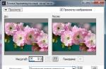
We open the resulting map in Max as a regular Bitmap, the image conversion dialog appears:

the main attention should be paid to the conversion option in the "Internal Storage" section, by default Max suggests discarding information about brightness and just marking bright and dark places with certain colors - 16 bit / chan mode, this will not suit us, so set the Real Pixels mode and click OK .
I used the selected map for a material similar to the material of the fixtures, on the glow parameter, and applied it to the box against the far wall
For comparison, two renders:
the first is the card in 16 bit mode:

due to the replacement of bright areas with white, illumination from bright areas is almost white light
the second one is real:

there is clearly a difference.
Using Photoshop, you can make an approximate analogue of hdr images from ordinary photos, for this you need to convert the work to 32-bit color, make a copy of the image, increase the brightness on the copy using a histogram (the brightness as such cannot be changed there) and overlay both images with the Multiply parameter (multiplier).
Here is a scene where the TV picture is obtained in this way:

in this scene there are three photometric light sources simulating 60 watt incandescent lamps.
Let's dwell on them in more detail.
Photometric light sources are needed to simulate real light sources in their physical parameters, but some conditions are necessary
Use metric units when creating a scene
Observe the real sizes of objects on the stage
FG or GI indirect lighting algorithm must be enabled, preferably both
The main characteristics of photometric sources are the temperature of the emitter, which gives the color of the light stream, and the power of the light source.
Since we are used to measuring power in watts, and we have only a superficial idea of \u200b\u200bthe source temperature, I will give a plate of the most common household light bulbs
|
Power |
Temperature in K |
|
|
12 volt - shop window lighting, less often table lamps |
||
|
Household incandescent lamps 220 volts |
||
|
Fluorescent lamps |
||
|
As such, they do not have a temperature, and are divided by the color of the limunifor: Cold white 4500k, Day white 6500k, Warm white 3000k |
||
|
Arc mercury/sodium |
||
|
The temperature is 6500 - 11000K, but as a rule, a filter is needed, for example, sodium ions color the light red, and the inert gases present add a blue-green spectrum. |
||
Now let's talk about sunlight.
The developers of the mental divided the sunlight into direct light from the solar disk - bright with strong shadows - mr Sun and filling from cloud cover and atmosphere with very blurry shadows - mr Sky.
When adding the mr Sky light source to the scene, it will be automatically proposed to add the mr Physical Sky shader to the environment, with which it is advisable to agree.

in the settings you need to specify the color of the sky at night "Night Color", at low brightness values - the multiplier color of the sky will tend to this color.
Adjust the height of the horizon and the color of the ground surface, add haze (Haze) and the parameters of the ratio of red and blue color in the sky (evening / day) in the Non - Physical Tuning section:

mr San's settings also have options for adjusting the horizon, brightness and color, haze, and also added an option for adjusting shadows - Softness - the softness of the shadow and the quality at the borders of the soft shadow: Softness Samples.
sample test room scenes
with the sun outside the window

and in cloudy weather

I forcibly increased the intensity of the light so that you can see the light filling the room and the shadows on the floor. In the first case, the rays are straight and practically parallel - a spot on the floor is illuminated and secondarily from the floor by reflection, a spot in the window area is illuminated. And in the second case, almost the entire room is lit. When rendering both scenes, FG was set to the Low profile, which caused a lot of noise in the lit areas.
Often when depicting rooms where light is coming from a window, it is desirable to enhance the effect of bright rays or the dusty atmosphere of a room by adding a Volume Light effect to light sources. On the mr Sun light source, this effect is not applied correctly, probably due to a different principle for calculating shadows, the illuminated volume is simply filled, without taking into account the shaded areas. Therefore, for such an effect, you will have to use standard sources.:

Let's finish with the rooms and move on to simulating ambient lighting
If we have an hdr map imitating the sky, then we can easily apply it to our scene. This is done by applying the map to the Skylight light source. The light source itself can be placed anywhere in the scene - it doesn't matter, the main thing is that FG is on, otherwise it will not work.
We click on the button labeled None (there is no map by default) and select our hdr image (as I described above), or specify a slot from the material editor where such a map is already open.
here is an example of a scene where a small building is depicted, around a moonlit night. The environment map is applied not only to the light source but also to the environment map slot.

we see soft lighting from the sky of the entire scene, as well as pronounced shadows from the moon.
And now a fly in the ointment:
For the picture shown above, I specifically used a dark map with a bright spot of the moon, which I additionally processed in Photoshop to increase the brightness of the moon and darken the sky, otherwise the effect of the map would not be noticeable. In fact, in MR, in my opinion, the algorithm for taking into account the brightness components of the map for the Skylight source does not work quite correctly.
I will give examples of scene comparison for MR and V-Ray.


in both cases, multiplier = 3, I did not change the rest of the map parameters, I tried to use materials with similar properties.
As you can see, in the second case, the picture is “tastier”. The only thing I want to note about Vi_rey is that it must be remembered that one and the same card for lighting and reflection cannot be used. Look carefully at the picture - where the moon is located according to the reflection and where the shadow from it is directed - the difference is 180 o. There is a parameter in the settings for map rotation, but you need to remember this!
True, I took the most difficult map - the moon is not bright and small, on good maps the differences are almost invisible, but the fact of different calculation is obvious. Let everyone draw their own conclusions.
It seems that this is all that I wanted to show as part of this lesson. In the end, I will dwell on some small features that, in my opinion, are worthy of attention.
- Glow material. In previous versions, it incorrectly illuminated itself. If not the entire surface of the material is lit, but only certain areas (a map is applied) or the material is part of the Blend material, then the luminous area will illuminate neighboring objects with a different material, but objects with the same material will not illuminate itself. Max 2008 doesn't have this problem. Here is an example scene:

the entire structure is made up of a single material based on Blend. As you can see, the material illuminates itself perfectly (there are no light sources on the stage).
- except using .hdr maps, you can also use .exr maps, which are less common but also carry light intensity information. The window for converting a file in exr format, when assigning a card:

- While creating animations where there are bright light sources or textures on the scene based on hdri images, the Motion Blur effect in all versions of Max up to 2008 inclusive does not work correctly, since the device of our vision (and camera matrices) is such that the brighter the spot, the brighter “blur track” it will leave. Happy owners of Max 2009 the kit includes an HDR Image Motion Blur(mi) shader, which is placed in the “Output” slot of the camera effects, which are available in the “Renderer” render settings:

this shader allows you to blur the image of not only objects in the scene, but also the background of the scene, on which the map with the image is applied.
For comparison
Blur on luminous scene objects

and for the background on the same map with the moon

This concludes the first part of the lesson. In the next part, I will touch on the problems of GI and light in volumes.