In this article, we'll look into the future of SCSI and look at some of the advantages and disadvantages of SCSI, SAS, and SATA interfaces.
In fact, the issue is a bit more complex than just replacing SCSI with SATA and SAS. Traditional parallel SCSI is a tried and tested interface that has been around for a long time. Currently, SCSI offers a very fast data transfer rate of 320 Megabytes per second (Mbps) using the modern Ultra320 SCSI interface. In addition, SCSI offers a wide range of features, including Command-Tag Queuing (a method of optimizing I/O commands to increase performance). SCSI hard drives are reliable; in a short distance, you can create a daisy chain of 15 devices connected to a SCSI link. These features make SCSI an excellent choice for high performance desktops and workstations, up to and including enterprise servers, to this day.
SAS hard drives use the SCSI command set and have the same reliability and performance as SCSI drives, but use a serial version of the SCSI interface at 300 Mbps. Although slightly slower than 320 Mbps SCSI, the SAS interface is capable of supporting up to 128 devices over longer distances than the Ultra320 and can expand to 16,000 devices per channel. SAS hard drives offer the same reliability and rotation speeds (10000-15000) as SCSI drives.
SATA drives are a little different. Where SCSI and SAS drives focus on performance and reliability, SATA drives trade them off in favor of massive capacity increases and cost reductions. For example, a SATA drive has now reached a capacity of 1 terabyte (TB). SATA is used where maximum capacity is needed, such as data backup or archiving. SATA now offers point-to-point connections at speeds up to 300 Mbps, and easily outperforms the traditional parallel ATA interface at 150 Mbps.
So what will happen to SCSI? It works great. The problem with traditional SCSI is that it's just coming to the end of its useful life. Parallel SCSI at 320 Mb/s will not run much faster on current SCSI cable lengths. In comparison, SATA drives will reach 600 Mb/s in the near future, SAS have plans to reach 1200 Mb/s. SATA drives can also work with the SAS interface, so these drives can be used simultaneously in some storage systems. The potential for increased scalability and data transfer performance far exceeds that of SCSI. But SCSI isn't going away anytime soon. We will see SCSI in small and medium servers for a few more years. As hardware upgrades, SCSI will be systematically replaced by SAS/SATA drives to get faster and more convenient connections.
"Courageously stepping on uncharted land" - IDE drives on SCSI controllers
With each new generation of drives, hard drive manufacturers pull out new aces from their sleeves: the latest models are faster, quieter and more voluminous than their predecessors. They have already reached the capacity of 200 GB - and soon we will see 300 GB disks. But disks of this size with SCSI interface are not available, and SCSI is the standard for the server market.
Powerful server systems must be reliable, fast, and resourceful in terms of power and capacity. The first two parameters are easily achieved by using the best SCSI controllers and the best hard drives. But increasing storage can cost a pretty penny.
So why don't we try to use cheaper IDE Solutions- they do the same job as their more expensive SCSI counterparts. However, several arguments speak against the use of IDE drives: the maximum number of devices, the reliability of modern hard drives, and the lack of controller functionality.
Taiwanese manufacturer Acard has developed an adapter that allows IDE drives to work on SCSI controllers.
In fact, such problems do not concern home users. Even if SCSI systems work faster, they are not so attractive due to their high cost. In addition to the money that you pay for a modern hard drive, you will also need to buy a node controller. If you need a RAID controller, then be prepared to shell out at least the cost of a Pentium 4.

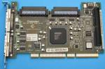
With two Ultra160 SCSI lanes, the Adaptec 39160 provides a level of flexibility that is hard to beat.
Today, IDE drives are characterized by high speed and volume. And as for the price, SCSI is not a competitor to them.
But the server segment dictates completely different rules of the game. It's not about extra gigabytes - the priority is given to maximum reliability and performance, since even an insignificant downtime of the server will cost serious money, and in the worst case, even call into question the existence of the company.
That is why SCSI solutions are so expensive: expensive development, high-quality components, and the market is relatively small.
However, not so long ago Maxtor announced its entry into the server segment of the market with a new line of drives with an IDE interface. With a low minimum performance and adequate reliability, the goal is to achieve a much higher capacity than SCSI drives (where the current maximum is 147 GB). In theory, the plan is good, because for the price of five Ultra320 SCSI drives, each 147 GB, you can buy 15 state-of-the-art IDE drives, each 200 GB.
The only thing missing today is the right controllers. There is little chance that manufacturers will release IDE versions of their high-end controllers. However, there are a huge number of SCSI host controllers on the market.
Aside from the IDE2SCSI adapters below, Acard is mainly known for its SCSI and IDE controllers and related products, as well as unusual data handling solutions such as CD or DVD ripping stations.

Also from Acard: dual-channel IDE RAID controller AEC-6880.

Unusual thing: IDE2SCSI adapter AEC7722, front view.
The adapter is as wide as a 5.25" drive and connects directly to the IDE hard drive. However, the current on the IDE bus is not enough to power the controller, so an external power connection is required.
For tests, we used an IBM (Hitachi) hard drive.

As you can see, the connected adapter protrudes slightly on the left. Before purchasing an adapter, be sure to check that you have enough space in your computer case.
Be careful when connecting the adapter, because the board will bend slightly under pressure.

There are no components placed on the back of the adapter. Just an IDE connector.

According to Acard, the adapter's maximum interface speed is 80 MB/s. Even if the peak transfer rate of modern disks may be higher, this throughput will be sufficient for most applications.

Chip, BIOS and jumpers (top). The last two are used to set the SCSI-ID.

The heart of the IDE2SCSI adapter is a controller made by Achip (ARC765-D).

View of the adapter from the front and back.

Upside down: Adaptec's SCSI host adapter looks for available drives. A 180 GB IDE drive from IBM was found.

The SCSI connector has 80 small pins (top). In contrast, the IDE has only 40 pins.

A typical Ultra160 SCSI cable has three to five drive connectors. For more expensive versions, the number of connectors can reach up to 15.

The SCSI specification provides for termination of both ends of the bus, that is, there must be a special resistor there to prevent signal reflections.
Testing
| test system | |
| CPU | Intel Pentium 4, 2.0 GHz 256 KB L2-Cache (Willamette) |
| mother board | Intel D845EBT, 845E chipset |
| Memory | 256 MB DDR/PC2100, CL2, Infineon |
| Controller | IDE: i845E UltraDMA/100-Controller (ICH4) SCSI: Adaptec AHA-39160 Ultra160-SCSI |
| video card | NVIDIA GeForce2 MX 400 |
| Network Card | 3COM 905TX PCI 100MBit |
| OS | Windows XP Pro 5.10.2600, SP1 |
| Tests | |
| High-end applications | ZD WinBench 99 - Highend Disk Winmark 1.2 |
| Performance | HD Tach 2.61, PC Mark 2002 (HD Test) |
| I/O performance | Intel I/O Meter |
| Drivers and settings | |
| Video driver | NVIDIA reference driver 29.42 |
| IDE driver | Intel Application Accelerator 2.2.2 |
| DirectX Version | 8.1 |
| Permissions | 1024x768 16bit 85Hz refresh |
To see how a modern IDE hard drive would perform on a SCSI controller with a typical setup, we tested the IBM IC35L180 test drive in both configurations.


Conclusion: useful but expensive
The result of the tests is clear: the difference between a hard drive running on an IDE and on an Adaptec 39160 SCSI controller is negligible in all important tests.
The slightly lower I/O performance is due to the need to convert interface protocols, which is quite important in a server environment. Each disk access operation is handled by the Achip controller. Thus, IDE hard drives with an adapter should not be used in disk-intensive applications (ie databases or web servers). In these areas, SCSI drives have a distinct advantage over their IDE counterparts, as they can provide more I/O operations per second.
SCSI adapters and IDE hard drives with adapters are interesting in applications where large hard drives are required. If you install larger hard drives, you can equip your storage with fewer drives, and more importantly, it will cost you much less than the SCSI option. Even if you install a few spare drives in case of IDE hard drive failure (in a large RAID cluster), you will still save a significant amount of money. Of course, the transition to such a configuration is, first of all, a matter of confidence in the manufacturer of hard drives.
If you are interested in the IDE2SCSI adapter, then we will disappoint you a little: it is by no means cheap. On the Acard website, prices start at $69, a pretty substantial price for a controller designed for budget-friendly solutions.
Therefore, using an Acard adapter makes sense only in cases where you save a lot of money by ditching SCSI drives and switching to bulky IDE drives, without taking into account additional expensive security measures (redundancy, mirroring, hot-swappable bays).
SCSI (Small Computer Systems Interface - System interface for small computers, pronounced in Russian as "skazi") - an interface designed to combine devices of various profiles into a single system: hard magnetic drives, scanners, streamers, CD-ROMs, etc. .P. The essence of the interface is to provide a flexible mechanism for managing these devices and the maximum speed of their operation as a single, but divisible mechanism.
The roots of the SCSI interface go back to the distant 1979, when the manufacturer of information storage devices M. Shugart was puzzled to find a universal interface standard for his disks, taking into account possible future needs. In the laboratories of M. Shugart, as a result, an interface was developed that supported logical and physical (head / cylinder / sector) addressing, based on protocols for 8-bit parallel data transfer over an interface consisting of several lines. This interface was named SASI (Shugart Associates Systems Interface - Shugart's Connecting System Interface). The interface, in addition to describing the protocols, also included several 6-bit commands; the downside was that the interface was designed to use only one host-device pair.
Later, in 1981, M. Shugart submitted the documentation on the SASI interface to the ANSI committee (American National Standards Institute - US National Standards Institute, analogue of GOST), which accepted it as the basis for working on the project, which was called SCSI. Most of the most important points from the SASI standard migrated to SCSI, for example, such important principles as device arbitration, bus release mechanisms, the ability to use more than one host adapter on the bus, and so on. In 1984, the working documentation of the SCSI standard was submitted to ANSI for consideration, and, after numerous adjustments and additions, in 1986, a document was adopted under the number X3.131-1986 - the first official SCSI standard, which is now commonly called SCSI-1. In addition to the SASI standard, SCSI-1 has acquired such important functionality as 10-bit commands, synchronous and asynchronous data transfer protocols, and the ability to connect up to 8 different devices to one host adapter. Following SCSI-1, the standards have evolved both in the direction of expanding the command language and in increasing and complicating protocols, and in increasing the bus width, increasing the speed and the number of devices connected to one host adapter. For current SCSI standards, the bus width is 16 bits, the number of connected devices is also 16.
The PC industry did not miss the emergence of a new standard, which was immediately adopted mainly by HDD manufacturers. On fig. 1, 2 show some of the first samples of SCSI disks.


Rice. 1, 2. The first samples of SCSI drives - SONY company (capacity 40 megabytes)
and Quantum (capacity 120 megabytes)
A Brief History of the SCSI Standard
The very first standard is SCSI-1; in this standard, up to eight devices, including the controller, could be connected to one bus. The interface contains advanced controls and at the same time is not focused on any particular type of device. It has an 8-bit data bus, the maximum transfer rate is up to 1.5 MB / s in asynchronous mode (according to the “request-acknowledgment” method), and up to 5 MB / s in synchronous mode (multiple requests - multiple confirmations method) . Parity can be used to detect errors. Electrically implemented as 24 lines (unipolar or differential), although the vast majority of devices use unipolar signals.
SCSI-2 is a significant evolution of basic SCSI. Increased transfer speed (up to 3 MB/s in asynchronous mode and up to 10 MB/s in synchronous mode) - Fast SCSI. New commands and messages added, parity support made mandatory. The possibility of expanding the data bus to 16 bits (Wide SCSI) was introduced, which provided speeds up to 20 MB / s. A new 68-pin connector has been introduced. The subsequent specification, SCSI-3, not only introduced new baud rates, but also greatly expanded the command system. In addition, other parallel and serial protocols can be used as a transmission medium, along with the traditional parallel bus interface: Fiber Channel, IEEE 1394 Firewire and Serial Storage Protocol (SSP).
Ultra SCSI interface, uses 20 MHz bus frequency. The Ultra/Wide SCSI interface supports 16 devices and provides transfer rates up to 40MB/s. Faster Ultra-2 Wide SCSI, providing transfer rates up to 80 MB/s. The following interfaces - Ultra-3 SCSI, Ultra 320 SCSI, Ultra 640 SCSI - did not bring anything fundamentally new to the standard, except for speed. They also remain with a bus width of 16 bits, and up to 16 devices can also be connected to the interface. Comparative characteristics of SCSI standards are given in Table 1.
Table 1. Comparative characteristics of SCSI standards
| Standard | Maximum bus speed, MB/sec. | Bus bit width | Maximum cable length, m | Maximum number of devices | ||
| The only mouth | LVD | HVD | ||||
| SCSI-1 | 5 | 8 | 6 | (3) | 25 | 8 |
| SCSI-2 | 10 | 8 | 3 | (3) | 25 | 8 |
| Wide SCSI-2 | 20 | 16 | 3 | (3) | 25 | 16 |
| SCSI-3 | 20 | 8 | 1.5 | (3) | 25 | 8 |
| Wide SCSI-3 | 40 | 16 | — | (3) | 25 | 16 |
| Ultra— 2 SCSI | 40 | 8 | (4) | 12 | 25 | 8 |
| Wide Ultra-2 SCSI | 80 | 16 | (4) | 12 | 25 | 16 |
| Ultra-3 SCSI,orUltra-160SCSI | 160 | 16 | (4) | 12 | (5) | 16 |
| Ultra 320 SCSI | 320 | 16 | (4) | 12 | (5) | 16 |
| Ultra 640SCSI | 640 | 16 | (4) | (7) | (5) | 16 |
What is a host adapter?
A host adapter is a device connected to the PC bus that provides a host (the meaning of the word "host" in relation to the standards describing data transfer interfaces (English host) most fully describes the phrase "bus master") communication with SCSI devices. The name "adapter" was not chosen by chance - this indicates that all the logic of the devices is located in the peripheral devices on the bus; for devices called "controller" the logic is located in themselves.
The following manufacturers make or have made SCSI host adapters in the past:
An example of a host adapter is the device shown in Fig. 3.

Rice. 3. SCSI host adapter from Adaptec
Modern manufacturers of SCSI hard drives
Currently, the HDD market is undergoing rapid evolution - new, high-speed Serial ATA standards are replacing Parallel ATA. And, although the new SATA devices have already come close in speed to SCSI devices, and somewhere they overtake them, SCSI devices remain still popular in High-End computers - servers and information arrays. This is due, first of all, to the high reliability of SCSI drives - both due to the relative simplicity of SCSI standards and a well-thought-out electrical interface, and due to the traditionally more thorough design and production study of devices. SCSI accounts for approximately 30 percent of the entire hard drive market, and it is unlikely that it will ever cross this line: equipping a PC with all the necessary cables, adapters, as well as buying the host adapter itself will cost about $ 100, drives will cost several times more. their IDE counterparts. Modern manufacturers of SCSI drives are:
The competition in the SCSI disk market is low - most likely because the market is full enough and does not develop as rapidly as the market for IDE devices - and this is primarily due to the fact that SCSI devices are used most often in servers, demand for which is not so great. The convenience of SCSI devices is that they can be easily replaced in the course of work, without shutting down and losing the server's performance. This is very important for servers, and not necessary for workstations. As a rule, servers (Fig. 4) are equipped with special sleds (Fig. 5), into which a disk in a special mount (Fig. 6) can be inserted very easily.

Rice. 4. Server equipped with SCSI disks

Rice. 5. SCSI drive bay

Rice. 6. SCSI drive bracket used in hot-swappable servers
It is worth noting that very often server manufacturers relabel drives, giving them their own brands. As an example, I will cite drives seized from Hewlett Packard and IBM e-Server servers (Fig. 7, 8), on which the real hard drive manufacturer can be recognized only by the model name; the author has also seen disks retrieved from Dell servers that did not even have this information.


Rice. 7, 8. Modern SCSI drives used in servers
SCSI connector types

Rice. 9. Types of SCSI connectors currently in use
SCSI devices can have various types of connectors for connecting them to the host adapter (see Figure 9) - this is primarily due to the design features of the device itself. The most commonly used HDD connector is HD68 (Fig. 10), a little less often - SCA80 (Fig. 11). In the distant past, in the late 80s and early 90s, almost all SCSI drives were connected to the host through the HE50 connector (Fig. 12). Currently, this connector is almost never found.


Rice. 10. HD68 connector.
Rice. 11. SCA80 connector.
Rice. 12. HE50 connector.
To connect devices of various connector configurations to the bus, specialized adapters may often be required. Such adapters, for example, are manufactured by SCS (http://www.scaadapters.com) and cost between $10 and $35 each. A complete set for working with any SCSI device is shown in fig. 13, in fig. 14 - 18 each adapter is shown separately

Rice. 13. Necessary adapters for connecting SCSI devices


Rice. 14 - 18. Same as fig. 13, separately.
How SCSI Works
To match the loads on the SCSI bus, terminators are used, which, according to their electrical properties, are divided into passive, active, and FPT terminators. Terminators must be powered, so the interface has Terminator Power lines. Passive terminators used in SCSI-1 devices are ordinary 132 ohm resistors. Active terminators are a stabilizer that produces the desired signal - while each line is connected to this stabilizer through a 110 ohm resistor. Currently, only active terminators are used, while auxiliary voltage sources are used - for these purposes, auxiliary diodes are usually used, which fix the voltage of the input signals at the required level. Finally, the FPT terminators (Forced Perfect Terminator - Accelerated Improved Terminator) are the improvement of active terminators, equipping them with emission limiters. Their application - in high-frequency versions of SCSI.
All SCSI devices are usually divided into initiators and executors. In this case, it should be taken into account that the bus can be standard (8 bits) or extended (16 bits) bit width. Given all this, the entire number of possible combinations of connecting devices can be reduced to four:
1. Standard initiator - standard executor
2. Extended Initiator - Extended Executor
3. Standard initiator - advanced executor
4. Extended initiator - standard executor
When connecting standard executors to extended initiators, problems cannot arise - the extended standard supports all the functions of the standard one, however, when connecting back, it may be difficult to connect terminators. In real life, these problems are easily solved using adapters (see above).
SCSI bus states are usually divided into phases. There are only five such phases: the bus is free, arbitration (at the same time, the initiator can gain control of the bus), selection (in this case, the initiator, who entered the arbitration phase first, selects the performer for further work), reselection (the performer confirms to the initiator that he has been chosen by him for operation and is ready for operation) and the information phase (request-transmission of commands, data, messages). The block diagram of the sequence of phases of one cycle of operation on the SCSI bus is shown in fig. 19.
After the selection phase, the initiator can time out, for which it can use two methods - perform a hardware reset or go into the "bus free" phase. In any case, the end of the cycle of work on the SCSI bus will be the setting of the status "command completed" or the transmission of the corresponding message with the release of the bus. Similar to the ATA standard, SCSI systems can use two protocols to reset the device - the hardware reset protocol (hard reset) and the software reset protocol (soft reset). In both cases, a one bit will be set on the Reset line, the differences in the types of resets lie in their mechanism and purpose - as a rule, a hardware reset is performed to reset operations across the entire system of SCSI devices, while software is used to reset only one device, not interfering with the work of others.

Rice. 19. Block diagram of the phase sequence of the SCSI bus
The SCSI bus uses nine control signals: BSY (Busy, Busy), SEL (Selection, Selection), C / D (Command / Data, Control / Data), I / O (Input / Output, Input / Output), MSG ( Message, Message), REQ (Request, Request), ACK (Acknowledge, Confirmation), RST (Reset, Reset), ATN (Attention, Attention). Busy, Select, and Reset signal sources can be either the initiator or the worker; only an executor can be the source of the Acknowledgment signal; other signals are the prerogative of the initiator. The types of information transfer are encoded by the bit combinations set for the Message, Control/Data, Input/Output signals, as shown in Table. 2.
Table 2. Types of information transfer on the SCSI bus
The interface is controlled by a message system. There are 28 of them in total, they can be single-byte, double-byte (one word) and extended. The message system is detailed in any SCSI standard.
To select a specific device on the SCSI bus, there is an identifier bit. As a rule, SCSI devices are hardware-configured, that is, the system identifies the device by the jumpers installed on it. The limitation on the number of connected devices in the standard (8 bit) and extended (16 bit) SCSI versions is imposed precisely by the existence of the identifier bit - in an 8 or 16 bit bus it is impossible to set more than 8 or 16 identification bits, respectively, and this also includes the identifier bit host adapter - that is, in other words, in addition to the host adapter on the bus, there can be 7 more devices for standard SCSI, and 15 for extended.
SCSI commands
| Command | Command code |
| Change definition (CHANGE DEFINITION) Compare (COMPARE) Copy (COPY) Copy and verify (COPY AND VERIFY) Format (FORMAT UNIT) Request (INQUIRY) Lock-Open Cache (LOCK-UNLOCK CACHE) Log selection (LOG SELECT) Log Sensitivity (LOG SENSE) Mode selection (MODE SELECT) Mode Sensitivity (MODE SENSE) Preamp (PRE-FETCH) Deny permission to change media (PREVENT-ALLOW MEDIUM REMOVAL) Reading (READ) Read buffer (READ BUFFER) Show capacity (READ CAPACITY) Read defective data (READ DEFECT DATA) Long reading (READ LONG) Reassign block (REASSIGN BLOCK) Receive diagnostic results (RECEIVE DIAGNOSTIC RESULTS) Release (RELEASE) Request Sensitivity (REQUEST SENSE) RESERVE Rezero device (REZERO UNIT) Find the same data (SEARCH DATA EQUAL) Find high data (SEARCH DATA HIGH) Find low data (SEARCH DATA LOW) Position yourself (SEEK) Diagnostic request (SEND DIAGNOSTIC) Set limit (SET LIMIT) Start-stop the device (START STOP UNIT) Synchronize cache (SYNCHRONIZE CACHE) Device readiness request (TEST UNIT READY) Verification (VERIFY) Write (WRITE) Record with verification (WRITE AND VERIFY) Write to Buffer (WRITE BUFFER) Long recording (WRITE LONG) Write the same (WRITE SAME) | 40h 39h 18h 3ah 04h 12h 36h 4ch 4Dh 15h, 55h 1Ah, 5Ah 34h 1Eh 08h 28h, 3ch 25h 37h 3Eh 07h 1Ch 17h 03h 16h 01h 31h 30h 32h 0bh 2Bh, 1Dh 33h 1Bh 35h 00h 2Fh 0 Ah 2ah 2Eh 3bh 3Fh 41h |
The table above lists the main SCSI standard commands applicable to the hard drive. As in the ATA standard, for the SCSI standard there are both mandatory commands, that is, those that must be supported by any SCSI device, and optional, optional commands, the support of which the device may not be provided. In addition to them, there are so-called vendor commands that are not described in the standard, specific to each manufacturer and often for each specific line of devices - commands that the manufacturer uses to repair or diagnose the device. These commands are, as a rule, a trade secret of the manufacturer and are not published anywhere.
SE,LVD,HVD
You will typically find markings on a SCSI device like the one shown in Figure 1. 20. This marking indicates the type of data transfer at the electrical level. The first - SCSI SE (Single Ended), denotes a type of data transfer when each signal on the bus is provided by one conductor. SCSI LVD (Low Voltage Differential) and SCSI HVD (High Voltage Differential) - low-voltage and high-voltage differential types - are physically organized in the same way: for each signal there are two conductors, one for the signal of positive polarity, the other for negative. The differences between HVD and LVD are in the voltage in the conductors, for LVD it is lower than for HVD.

Rice. 20. Designations on SCSI devices that carry information about the electrical type of data transfer
It is logical that HVD and LVD devices are incompatible - if you connect an LVD device to the bus of an HVD device, the first one will inevitably die due to signal overvoltage. The same can be said about SE and LVD devices - the cables for them are the same, but due to electrical characteristics they are not compatible. However, LVD devices can be connected to SE conductors, as they recognize voltages on the bus and if they receive a bipolar signal in one pair of conductors, they can switch to using it. Typically, devices that can operate in both modes are marked with a special LVD/SE icon.
Compatibility of all types of devices on the same bus is usually not required, however, if such a need arises, the use of specialized adapters solves this problem quite easily (see above).
The continuous increase in the clock frequency of the bus has led to the need to limit the maximum length of the connecting cable in the Ultra SCSI interface to one and a half meters. This is quite inconvenient when using external high-speed SCSI devices, but more than enough to ensure the connection of devices inside the PC case.
Synopsis. Prospects and opportunities
The SCSI interface is very productive and reliable, but it also has a considerable number of disadvantages. First of all, this is the high cost of the devices themselves - both drives and controllers. The next disadvantage is the complexity of configuration and management, which can only be handled by trained people. Finally, the last drawback of the interface, which makes it even less attractive to the user, is the impossibility of transferring the media to another PC if it is not equipped with a specialized SCSI adapter ...
The use of SCSI devices is inappropriate for the standard PC market for a very simple reason: the high price. However, manufacturers do not set themselves the goal of winning over the average consumer: it just so happened historically that SCSI drives are mainly a server standard, and IDE is a workstation standard.
Meanwhile, SCSI drives are on the heels of the latest IDE device standard: SATA. The speed and performance of SATA devices is very high, and their use in servers is becoming more and more popular. The only drawback of SATA is a rather flimsy connector, which is the reason for the rather frequent failures of these devices. I think that the SCSI interface will undoubtedly win the battle with SATA in the field of server drives.
The development of the SCSI standard promises us in the future faster devices with traditional SCSI reliability; it is not necessary to predict the imminent departure of SCSI devices from the market.
Serial Attached SCSI (SAS)
The latest trend in the world of SCSI devices is Serial Attached SCSI, an interface that uses three data transfer protocols (SSP - Serial SCSI Protocol, STP - Serial ATA Tunneled Protocol, SMP - Serial Management Protocol). As can be seen from the names of the protocols, the first two are intended for data transfer itself, the latter is intended for interface control. Drives with this interface are now manufactured by Seagate, Samsung and Fujitsu.
A feature of this interface is that the signal is transmitted not over two (as in SATA), but over four conductors (one pair is for receiving the signal, the other is for sending it). Claimed data transfer rates are 1.5 and 3.0 GB/s.
SCSI - Small Computer System Interface
Despite the seeming dominance of devices with IDE/EIDE interface, SCSI hard drives still account for about 27% of the market in terms of output. This is usually explained by the fact that these interfaces are designed for different market segments - IDE for "popular and cheap systems", and SCSI for "high-performance workstations." However, many may argue that recently IDE hard drives have achieved the performance of SCSI and are much cheaper. And the IDE controller, which is already the fastest, is usually located on the motherboard and does not require additional material costs, while a good SCSI controller costs at least $100. But there are people who persistently prefer this interface with a hard-to-read name. By the way, SCSI is read and pronounced as " tell me". I also partially attribute myself to such people and will try to attract at least a few more users to our side, as well as tell a little about SCSI itself.
SCSI vs IDE
The debate "Which is better: IDE or SCSI" is one of the most common in many newsgroups. The number of messages and articles on this topic is very large. However, this question, like the famous "Windows NT or OS / 2 or Unix", in this formulation is unsolvable. The most frequent and correct reaction to them is “What for?”. After considering this issue in more detail, you will be able to make a decision for yourself about the need for SCSI for yourself.
Let's tell you in more detail what a simple SCSI controller can give compared to an IDE and why you should choose it or not.
| SCSI offer | EIDE/ATAPI objections | SCSI response |
|---|---|---|
| the ability to connect 7 devices to one controller (to Wide - 15) | it is not difficult to install 4 IDE controllers and there will be 8 devices in total | for each IDE controller you need an interrupt! And only 2 will be with UDMA/33. And 4 UWSCSI is 60 devices :) |
| wide range of connected devices | IDE has CDD, ZIP, MO, CD-R, CD-RW | Do you have drivers and programs for all this? and more? but for SCSI you can use any, including those included in the OS |
| Ability to connect both internal and external devices | ? removable rack or LPT-IDE | :) |
| the total length of the SCSI cable can be up to 25 meters. In normal versions 3-6m * | if you do not overclock the PCI bus, you can also by a meter | few! |
| you can use caching and RAID technologies to dramatically improve performance and reliability | there used to be caching Tekrams, and now there are RAID for IDE | it doesn't work and it's not serious at all |
* It should be noted that when using the Ultra or Ultra Wide SCSI interface, there are additional restrictions on the quality of connecting cables and their length, as a result of which the maximum connection length can be significantly reduced.
In order not to give the impression that the IDE is very bad and you should be ashamed of using it, we also note the positive qualities of the IDE interface, partly in the light of the above table:
- Price. Undoubtedly sometimes it very important.
- Not everyone needs to connect 4 HDDs and 3 CDDs. Often two IDE channels are more than enough, and all sorts of scanners come with their own cards.
- It is difficult to use a cable in a minitower case, it is longer than 80cm :)
- IDE HD is much easier to install, there is only one jumper, not 4-16 like on SCSI :)
- Most motherboards already have an IDE controller
- For IDE devices, the bus is always 16 bits, and for models comparable in price, IDE wins in speed.
Now about the price. The simplest SCSI to ISA bus costs about $20, but now nobody needs such ones, so you can find cheaper ones. The next option is a controller on the PCI bus. The simplest version of FastSCSI costs about $40. However, there are now many motherboards that can install the Adaptec 7880 UltraWideSCSI for as little as +$70. Even the famous ASUS P55T2P4 and P2L97 have SCSI options. For UWSCSI cards, the price ranges from $100 to $600. There are also dual-channel (like IDE on Intel Triton HX/VX/TX) controllers. Their price is naturally higher. Note that in the case of SCSI, in contrast to IDE, where it is difficult to come up with something new, for additional money, controllers can be expanded with the functions of a cache controller, RAID-0..5, hotswap, etc., so talking about the top controller cost limit is not quite correct.
And finally, about speed. As you know, today the maximum information transfer rate on the IDE bus is 33 Mb / s. For UWSCSI, a similar parameter reaches 40 Mb / s. The main advantages of SCSI are manifested when working in multitasking environments (well, not much in Windows95 :). Many of the benchmarks given under WindowsNT show the undoubted advantage of SCSI. Perhaps this is the most popular OS today, for which the use of SCSI is more than justified. There may also be specific tasks (related, for example, to video processing) in which it is simply impossible to use the IDE. We will not talk about differences in internal architectures that also affect performance in this article, since there are too many special terms. We only note that while watching the development of the IDE, we are surprised to notice that it acquires many features of SCSI, but, let's hope, they will not merge at all.
What does a SCSI controller look like and what does it consist of?
Here is a picture of the simplest FastSCSI controller on the PCI bus.
As you can see, most of the space is occupied by connectors. The largest (and oldest) is the 8-bit internal connector, often called narrow, it is similar to the IDE connector, only it has 50 pins instead of 40. Most controllers also have an external connector, as the name implies, you can and should connect external SCSI devices to it. The picture shows a mini-sub D connector with 50 pins.
For Wide devices, a similar one is used, but with 68 pins, and the fastening is also used not in the form of latches, but on screws - like in COM mice and printers. It is even smaller than narrow due to the higher contact density. (By the way, despite the name, wide plume is also narrower than narrow). Sometimes you can also find the old version of the external connector - just centronix. You can meet the same (outwardly, but not functionally :) on your printer. Some devices, such as the IOmega ZIP Plus and those designed for Macs, use a regular 25 pin Cannon (D-SUB) like a modem. Mini-centronics is also used for external high-speed connections. Here is the complete table:
(almost original dimensions)
| Internal | |
Low Density 50-pin |
connection of internal narrow devices - HDD, CD-ROM, CD-R, MO, ZIP. (like IDE, only 50 pins) |
High Density 68-pin |
connection of internal wide devices, mainly HDD |
| External | |
DB-25 |
connection of external slow devices, mainly scanners, IOmega Zip Plus. most common on Mac. (like a modem) |
 Low Density 50-pin |
or Centronics 50-pin. external connection of scanners, streamers. usually SCSI-1 |
High Density 50-pin |
or Micro DB50, Mini DB50. standard external narrow connector |
High Density 68-pin |
or Micro DB68, Mini DB68. standard external wide connector |
High Density 68-pin |
or Micro Centronics. according to some sources it is used for external connection of SCSI devices |
For the operation of any device, as you know, software support is required. For most IDE devices, the minimum one is built into the BIOS of the motherboard, for the rest, drivers for various operating systems are required. For SCSI devices, things are a little more complicated. To boot from a SCSI hard drive and work in DOS, you need your own SCSI BIOS. There are 3 options here.
- a microcircuit with SCSI BIOS is on the controller itself (as on VGA cards). When the computer is booted, it is activated and allows you to boot from a SCSI hard disk or, for example, CDROM, MO. When using a non-trivial operating system (Windows NT, OS/2, *nix), drivers are always used to work with SCSI devices. They are also required for non-hard disk devices to work under DOS.
- The SCSI BIOS image is flashed into the flash BIOS of the motherboard. Further on p.1. Usually, a SCSI BIOS is added to the motherboard BIOS for a controller based on the NCR 810 chip, Symbios Logic SYM53C810 (it is on the first picture) or Adaptec 78xx. You can control this process and change the SCSI BIOS to a newer version if desired. If there is a SCSI controller on the motherboard, this approach is used. This option is also more cost-effective :) - a controller without a BIOS chip is cheaper.
- There is no SCSI BIOS at all. All SCSI devices work only with operating system drivers.
In addition to supporting booting from SCSI devices, the BIOS usually has several other functions: configuring the adapter, checking the surface of disks, low-level formatting, setting SCSI device initialization parameters, setting the boot device number, etc.
The next remark follows from the first. As you know, motherboards usually have CMOS. In it, the BIOS stores the board settings, including the configuration of hard drives. The SCSI BIOS often needs to store the configuration of the SCSI devices as well. This role is usually performed by a small chip like 93C46 (flash). It connects to the main SCSI chip. It has only 8 legs and several tens of bytes of memory, but its contents are preserved even when the power is turned off. In this SCSI chip, the BIOS can store both SCSI device settings and its own. In the general case, its presence is not associated with the presence of a chip with a SCSI BIOS, but, as practice shows, they are usually installed together.

On the next picture you can see the ASUSTeK UltraWide SCSI controller. It already has a SCSI BIOS chip. You can also see the internal and external Wide connectors.

The last (I couldn't find any more quickly :) picture shows a dual-channel Ultra Wide SCSI controller. Its specification includes the following items: RAID levels 0,1,3,5; Failure Drive Rebuilding ; Hot Swap and on-line Rebuilding; cache memory 2, 4, 8, 16, 32 Mb; Flash EEPROM for SCSI BIOS. The 486 processor is very clearly visible, which is apparently trying to manage all this stuff.
You can also find on the SCSI controller board
- SCSI bus activity LED and/or connector for its connection
- memory module connectors
- floppy disk controller (mostly on older Adaptec boards)
- IDE controller
- sound card (on ASUSTeK cards for MediaBus)
- VGA card
Other SCSI cards
Scanners and other slow SCSI devices often come with a simple SCSI controller. Usually this is a SCSI-1 controller on the ISA bus 16 or even 8 bits with one (external or internal) connector. It does not have a BIOS, eeprom, it often works without interruptions (polling mode), sometimes it supports only one (not 7) device. Basically, such a controller can only be used with your device, because. there are drivers for it. However, with a certain skill, you can connect to it, for example, a hard drive or streamer. This is justified only in the absence of money and the availability of time (or sports interest :), because a standard SCSI controller, as already mentioned, can be purchased for $20-40 and have an order of magnitude fewer problems and much more opportunities.
SCSI specifications
The main characteristics of the SCSI bus are
- its width is 8 or 16 bits. Or, in other words, "narrow" or "wide".
- speed (roughly - the frequency with which the bus is clocked)
- physical interface type (unipolar, differential, optics...). sometimes it can be called a type of connector to connect
The speed is affected mainly by the first two parameters. Usually they are written as prefixes to the word SCSI.
The maximum transfer rate of the device-controller is easy to calculate. To do this, you just need to take the bus frequency, and if "Wide" is available, multiply it by 2. For example - FastSCSI - 10Mb / s, Ultra2WideSCSI - 80Mb / s. Note that WideSCSI usually means WideFastSCSI, just like Ultra2, I only know the Wide version and only with the LVD interface.
Let's take a look at the options for SCSI interfaces using Seagate hard drive designations as an example. In the model name, the last 1-2 letters indicate the interface, i.e. the same disk can be produced with different interfaces, for example Baracuda 9LP - ST34573N, ST34573W, ST34573WC, ST34573WD, ST34573DC, ST34573LW, ST34573LC.
| DC | 80-pin Differential |
| FC | fiber channel |
| N | 50-pin SCSI connector |
| ND | 50-pin Differential SCSI connector |
| W | 68-pin Wide SCSI connector |
| WC | 80-pin Single connector SCSI |
| WD | 68-pin Wide Differential SCSI connector |
| LW | 68-pin Wide SCSI connector, low-voltage Differential |
| LC | 80-pin Single connector SCSI connector, low-voltage Differential |
In everyday life, there are mainly interfaces designated N and W. Their "Differential" options provide increased noise immunity and increased allowable length of the SCSI bus. "Low-voltage" is applied with the new Ultra2 protocol. "Single connector" are used mainly in hot-swap configurations, because combine SCSI power and ground signals in a single connector. Fiber Channel is more like a LAN interface than SCSI because it is a serial interface. A speed of 100Mb / s is quite common for him. Used in Hi-End configurations.
SCSI devices
It is not possible to list all SCSI devices, here are just a few of their types: hard disk, CD-ROM, CD-R, CD-RW, Tape (streamer), MO (magneto-optical drive), ZIP, Jaz, SyQuest, scanner. Among the more exotic, we note Solid State disks (SSD) - a very fast mass storage device on chips and IDE RAID - a box of n IDE disks that pretends to be one large SCSI disk. In general, we can assume that all devices on the SCSI bus are the same and that one set of commands is used to work with them. Of course, as the SCSI physical layer evolved, so did the software interface. One of the most common today is ASPI. On top of this interface, you can use drivers for scanners, CD-ROMs, MO. For example, the correct CD-ROM driver can work with any device on any controller, as long as the controller has an ASPI driver. By the way, Windows95 emulates ASPI even for IDE/ATAPI devices. This can be seen, for example, in programs such as EZ-SCSI and Corel SCSI. Each device on the SCSI bus has its own number. This number is called the SCSI ID. For devices on a narrow SCSI bus, it can be from 0 to 7, on a wide one, respectively, from 0 to 15. The SCSI controller, which is a peer SCSI device, also has its own number, usually 7. Note that if you have one controller, but there are both narrow and wide connectors, then the SCSI bus is still one, and all devices on it must have unique numbers. For some purposes, for example, CD-ROM device libraries, LUN is also used - the logical number of the device. If there are 8 CD-ROMs in the library, then it has a SCSI ID, for example, 6, and logically CD-ROMs differ in LUNs. For the controller, all this looks like SCSI ID - LUN pairs, in our example 6-0, 6-1, ..., 6-7 . LUN support must be enabled in the SCSI BIOS if needed. The SCSI ID is usually set using jumpers (although there are new standards in SCSI similar to Plug&Play that do not require jumpers). They can also set the following parameters: parity check, terminator enable, terminator power supply, disk enable by controller command,
Installation
To install a SCSI controller and device, you need to have at least - themselves and also a SCSI cable :). Also useful is a free expansion slot in your PC, a free interrupt for that slot, 1-5 correct screws or screws, 2 to 8 different jumpers, a floppy drive or CD-ROM (already plugged in:) for driver media. More complex configurations may include external SCSI cables, external terminators (see below), Wide-Narrow adapters, and so on. Often there are questions about the ability to connect Fast / Ultra / Narrow / Wide devices in various combinations. For the most common devices, the general rule in this case is: if the connectors match, then you can connect. In other words, in this case it is important to distinguish between Narrow/Wide and ignore Fast/Ultra. (Leaves Ultra2 aside as it only exists in the LVD connector/interface variant). However, speed and reliability can drop significantly. See the SCSI Specifications / Interfaces section above for more details. In addition, there are various narrow-wide adapters, but their use is highly discouraged.
Controller
As already mentioned, the controller usually has SCSI ID=7. If you can think of a reason why this number needs to be changed, do it through the SCSI BIOS. You can also configure: support for ultra speeds, support for more than two drives, support for removable as a drive at boot time, etc. For each of the devices on the SCSI bus, you can configure: parity, turn-on delay (so that not all 7 drives turn on at the same time), maximum speed of the device. For non-PnP controllers on the ISA bus, remember to set the interrupt it uses in the BIOS SETUP to "Legal ISA". For a PCI controller, check that it also got an interrupt, and it does not share it with anyone, although this is often not important for the latest models.
Terminators
Perhaps someone remembers such a hard drive interface as ST506 (MFM / RLL), where the termination of the data cable on the last drive was just used. Terminators were also used in floppy disk drives, but for a very long time. The purpose of using terminators is to ensure signal level matching, reduce attenuation and interference. They say that problems with terminators are the most common, but if you do everything carefully, they will not arise. Each SCSI device has the ability to enable or disable terminators. The exceptions are some scanners that have bus termination permanently enabled and external devices with a bus pass-through. Terminators options:
- internal. usually found on hard drives. switched on by setting one jumper
- automatic. most SCSI controllers have these. they decide whether to join or not
- in the form of resistor assemblies. on some CD-ROMs and CD-Rs they are. are turned off by deleting all assemblies from the panels.
- external. as in point 3, but more beautiful. for example on an HP T4e tape drive. the device (usually external) has two SCSI connectors. one includes a cable to the controller, the other - a terminator or a cable to the next device in the chain.
In addition, terminators can be passive or active. Today, most are active, which provide greater noise immunity and reliability at high speeds. You can usually determine which one is used on a SCSI device by the way it is turned on. If this is one jumper, or it is automatic, then most likely it is active. And if to turn it off it is necessary to pull out 1-2 resistor assemblies from the device, then it is passive. In principle, bus termination from different ends with different types of terminators is possible, but only at low speeds. By the way, this is another argument in favor of separating slow and fast devices into different controllers or channels.
More details about terminators are written in the description of each device. Termination rules are often drawn in the adapter manual. The main thing sounds like this: the SCSI bus must be terminated at both ends. Here we will consider the most common options for devices on the same SCSI bus (wide or narrow)

The simplest option: a controller and one device (external or internal - it does not matter). Terminators must be enabled on both the controller and the device (or device)

Variant with multiple internal devices. The terminator is enabled only on the latter and on the controller.

There are both internal and external devices. Terminators are enabled on the outermost and innermost devices.

There are internal and several external devices. Terminators on the internal and in the last external device
The situation is a little more complicated when narrow and wide devices are used simultaneously on the same controller (bus). Imagine that we have two 8-bit buses, which in fact are just the high and low bytes of the wide bus (in the descriptions and the SCSI BIOS, this is called High byte / Low byte). Now, following the above rules, you need to terminate both of these buses. Usually in such cases, the controller can independently terminate the high and low bytes of the wide bus. In this situation, the narrow bus is an extension of the low byte of the wide bus. Here is one example:

Using Narrow and Wide Devices on the Same SCSI Bus
In principle, this is possible, just pay attention to the termination. However, it is better not to do so. Since the coexistence on the same bus of fast (wide is usually UltraWide SCSI) and slow devices (narrow is usually only Fast SCSI or even SCSI-1) is not good.
Homework: There are 3 connectors on the Wide controller: external and internal wide and internal narrow. Three cables with devices can be connected to them. Question: On which devices do I need to enable terminators?
Using a Narrow device on a Wide controller (bus)
This option is quite workable. You only need to use a wide-narrow adapter, or it can be an external SCSI cable with a narrow connector on one end and a wide connector on the other. Most often, such a need arises when connecting external narrow devices to a wide controller, since it usually has a wide external connector. If you still use adapters, pay attention to termination! When connecting an external narrow device to the wide connector, the adapter must terminate high byte. If a narrow device is connected to the internal wide connector, then the adapter simply converts the connectors (i.e., reduces the number of wires from 68 to 50).
Hard drives
Connecting hard drives is very simple, you only need to take care of two things - the terminator and the SCSI ID. Usually, a new disk has termination enabled, and the number is set to 6 or 2. Therefore, if you install the first disk, then there is nothing to worry about, and if not, then you need to check these settings. Another note about SCSI IDs is that older Adaptec controllers can only boot from 0 or 1.
The next step in the installation is formatting the drive. It is considered good practice to format the disk on a new controller before using it. This is due to the fact that different manufacturers of SCSI adapters use different sector translation schemes (it can be compared with LBA, CHS, LARGE for IDE disks) and during transfer, the disk may work poorly or not at all. If the disk on the new controller does not work, try formatting it with the format command, and if it does not help, then from the SCSI BIOS (I personally have not seen such options).
If you are connecting more than two hard drives or drives larger than 2G, you may need to change the SCSI BIOS settings. When connecting removable devices, such as the IOmega Jaz, the SCSI BIOS options must be set to boot from them. The description of the possible options is too long, maybe it will be given here later, but for now - read the descriptions, there's nothing wrong there :).
CD-ROM, CD-R, CD-RW
These DOS devices require a driver. It is usually installed on top of the ASPI driver. When running outside of DOS, no drivers are usually required. Optionally, you can set the controller parameter to boot from CD. To work with CD-R/CD-RW devices in recording mode, you will need special software (eg Adaptec EZ-CD Pro).
streamers
Similarly, CD-ROM SCSI tape drives can run most operating systems with standard drivers. It is very fortunate that, for example, under WindowsNT, you can use the standard backup program, and not specialized software.
Scanners
Usually scanners come with their own card. Sometimes it is completely “its own”, like, for example, Mustek Paragon 600N, and sometimes it’s just the most simplified version of standard SCSI. In principle, using the scanner with it should not cause problems, but sometimes connecting the scanner to another controller (if the scanner has such a possibility) can be useful. Scanning A4 with 32bit color at 600dpi is a picture of about 90Mb and transferring this amount of information through the 8bit ISA bus not only takes a lot of time, but also slows down the PC a lot, because. drivers for this standard card are usually 16-bit (example - Mustek Paragon 800IISP). A cheap FastSCSI PCI controller usually acts as an additional one. Less or more productive will not give anything new. This option also has a remark - you need to make sure that the scanner (or more importantly - its drivers) can work with your new controller in your configuration. For example, Mustek Paragon 800IISP drivers are designed for their own card or any ASPI compatible one.
When choosing a SCSI controller, you need to pay attention to several parameters (in random order and with a lot of redundancy)
- your requirements and tasks
- compatibility
- reputation of the card manufacturer
- reputation of the chip manufacturer
- availability of drivers
- technical support
- price
- advice from friends and acquaintances
- personal preferences
- appearance and equipment
FastSCSI PCI controller - Tekram DC-390. This controller is built on the basis of the well-known AMD chip, which guarantees operation under most operating systems with built-in drivers, but can also be used from Tekram. There is a small and pretty SCSI BIOS.
Controllers based on the Symbios Logic SYM53C810 chip are well known to most operating systems. SCSI BIOS for it is included in almost any AWARD BIOS for motherboards. Very cheap and yet workable.
UltraWideSCSI PCI controller - Adaptec AHA2940UW. One of the most popular today, although it is already losing ground. However, it is still functional. Well, a little slow and expensive, but it works under all common operating systems.
Controllers on the Symbios Logic 53C875 chip. Many note its speed and reliability.
Devices
HDD - well, of course Seagate Cheetah - it's hard to argue with RPM 10000. But without additional cooling fans, this drive will not last long :(. Other series of Seagate drives - Barracuda and Hawk - are also distinguished by reliability.
The rest (CD-ROM, Tape, CD-R and others) are all to your liking. SCSI devices are produced by many well-known companies. For example HP, Sony, Plextor, Yamaha.
In preparing the article, materials were used
companies IBM, Seagate, ASUSTeK, Tekram
| General information about interfaces………………………………………. | ||
| Classification of interfaces……………………………………………… | ||
| The history of the creation of the SCSI interface…………………………………… | ||
| Evolution of SCSI standards……………………………………………….. | ||
| What does a SCSI controller look like and what does it consist of……………………. | ||
| SCSI concept…………………………………………………………. | ||
| SCSI bus phases………………………………………………….. | ||
| SCSI Commands……………………………………………………………… | ||
| Host adapters…………………………………………………………. | ||
| SCSI cables……………………………………………………………... | ||
| Software support for SCSI devices……………………………... | ||
| Hardware programming of peripheral devices… | ||
| SCSI vs IDE…………………………………………………………… | ||
| | |
|
| Bibliography……………………………………………………… | ||
| | |
1. General information about interfaces
The creation of modern computer technology is associated with the task of combining into one complex various computer blocks, information storage and display devices, data equipment and the computer itself. This task is assigned to unified interface systems - interfaces. An interface is understood as a set of circuitry means that provide direct interaction between the constituent elements of a computer system. An interface provides an interconnection between the constituent functional units or devices of a system.
The main purpose of the interface is the unification of intra-system and inter-system communications and interface devices in order to effectively implement progressive methods for designing functional elements of a computer system.
2. Classification of interfaces
1) Machine interfaces are designed to organize connections between the constituent elements of a computer, i.e. directly for their construction and connection with the external environment.
2) Peripheral equipment interfaces perform the functions of interfacing processors, controllers, storage devices and data transmission equipment.
3) The interfaces of multiprocessor systems are basically trunk interface systems oriented into a single complex of several processors, memory modules, memory controllers, limited in space.
4) Distributed aircraft interfaces are designed to integrate information processing facilities located at a considerable distance.
The development of interfaces is carried out in the direction of increasing the level of unification of interface equipment and standardization of compatibility conditions, modernization of existing interfaces, creation of fundamentally new interfaces.
3. History creating an interface SCSI
The name Shugart is familiar to many: it belongs to one of the brightest pioneers and ideologists of the "storage" industry - the legendary silicon Olympian (in the sense of the inhabitant of the Silicon Valley Olympus) Alan F. Shugart, who led the development of floppy and RIGID at IBM, then worked at Memorex. In 1973, Shugart raised capital from outside and formed a 5.25-inch FDD drive company, Shugart Associates. This firm worked under his management for a year, after which Shugart was kicked out by the very people who invested in the undertaking. Shugart recovered from the blow for six years - during this period he even bought a fishing boat and became a professional fisherman. But the craving for high-tech did not go away: in 1979, together with Finis Conner, he founded Seagate Technologies (originally Shugart Technologies), after which he remained its leader for almost two decades, during which the company became the largest independent manufacturer of hard drives (albeit from Seagate in 1998, Shugart was "flooded", but that's a completely different story).
We are more interested in Shugart Associates, since it was they who developed the SASI interface, the earliest version of the SCSI bus, in 1979. Expanding the SASI abbreviation is currently difficult, the first two letters reliably mean Shugart Associates, the fourth - Interface, and the third stands for System, Systems or Standard in different sources (I think the correct version is still the latter). The capabilities of SASI were very modest even compared to the first version of SCSI - the transfer rate was only 1.5 MB / s, the interface had a very limited set of commands. However, the ideas embedded in SASI carried a lot of progressive: instead of the then ubiquitous analog serial transmission, 8-bit parallel digital was used, instead of a bunch of control lines, the interface provided a set of commands, and it worked at the logical level, allowing you to address blocks, not physical heads , cylinders and sectors.
Two years later, in late 1981, to spur industry acceptance of the interface, Shugart Associates partnered with NCR (National Cash Register) to apply to ANSI to form a technical committee to refine and standardize the interface. Such a committee, X3T9.2, was formed in 1982, and the interface name changed to the impersonal descriptive SCSI. Over the next few years, the standard was refined and improved: the bandwidth expanded, instruction sets were added - for printers, streamers, processors, WORM and ROM devices. (It should be noted that SCSI, unlike SASI, has become not just a disk interface, but a kind of system bus: theoretically, a complete system can be assembled on a “bare” SCSI by connecting a processor, memory, drives, and peripherals.) After the introduction of a draft version of SCSI in 1984 In the year following ANSI approval, many firms began to produce products more or less compatible with this proto-standard. The first official standard - X3.131-1986 - was adopted in 1986 (with the advent of subsequent versions, it became known as SCSI-1).
Subsequent additions and improvements led to the creation of the SCSI-2 specification.
4. Evolution of SCSI standards
The SCSI specifications strictly define the physical and electrical parameters of the interface and the minimum number of commands. The use of these commands became the main advantage of the SCSI interface, as it made it manageable. Developed in December 1985, the SCSI-1 specification provided for data transfer over a bus with a width of 8 bits and a frequency of 5 MHz. The data transfer rate on the SCSI bus in standard asynchronous mode (or handshake mode, i.e. when acknowledgment is required after each data send) is about 3 Mb / s. When transmitted in synchronous mode, the SCSI bus is capable of developing a throughput of about 5 Mb / s.
The devices were connected in a chain one after another. The first device connected to the SCSI interface on the host computer, the second connected to the first, and so on (see Figure 1). The first and last devices in the chain had to be terminated. On all other devices, termination had to be disabled. Devices were identified by a jumper or switch ID (0 to 7), with the host bus adapter typically assigned ID=7 as giving the highest bus access priority.
Figure 1. Typical scheme for connecting SCSI devices in the form of a chain.
The standard did not oblige the use of any particular type of connectors (connectors), but only described the purpose of the contacts. The most widely used D-Ribbon type Centronics connectors for PCs, as well as DB-25 for Macintosh. Termination was predominantly passive, while active or controlled termination was used only by individual manufacturers.
In March 1990, the SCSI-2 (Fast SCSI) specification was developed and officially approved in 1992, which defines 18 basic SCSI commands (Common Command Set, CCS), mandatory for all peripheral devices, as well as additional commands for CD- ROM and other peripherals. It became possible to exchange data without the participation of the central processor. There were "queues" - the ability to accept chains of up to 256 commands and process them autonomously in an optimized order. And if the controller of the destination executive device received a command that does not require any external interactions, then this controller will not occupy the bus until it becomes necessary to transfer some data. Here you can see a major advantage of SCSI over IDE, especially in multitasking environments: the IDE bus acts as a passive signal path from the CPU - it must execute one command first before initiating another.
Specification extensions have also appeared, the designations of which can often be seen in price lists. The basic 8-bit version - Fast SCSI (SCSI-2) - has a throughput of 10 Mbps. The Wide SCSI-2 modification is a 16-bit version of Fast SCSI (SCSI-2) and, accordingly, has a double data transfer rate, and also allows you to connect up to 15 peripheral devices. The Ultra prefix denotes an operating frequency increased to 20 MHz, and Ultra2 controllers are capable of transmitting data at a frequency of 40 MHz. Very often there are designations Ultra Wide or Ultra2 Wide. This means that combinations of options are used. So, for example, Ultra2 Wide devices can exchange information with a maximum speed of 80 Mb / s.
The Ultra160/m SCSI specification was adopted on September 14, 1998. The main components of Ultra160/m SCSI were: double synchronization during data transfer (Double Transition Clocking), data integrity control through the use of a cyclic redundancy code (CRC), environment control (Domain Validation). A data transfer rate of 160 Mbps is achieved by using both edges of the challenge/acknowledge signal to synchronize the data. Accordingly, this allows developers to increase performance or reliability, as it becomes possible to use up to 160 Mb/s bus bandwidth with existing Ultra2 SCSI interconnect cables, or to increase the reliability of the Ultra2 SCSI (80 Mb/s) interface by reducing the frequency at which synchronization occurs.
With regard to data integrity control through the use of cyclic redundancy code (CRC), the Ultra160/m uses the same method used in FDDI, CSMA-CD-based LANs and fiber optic data links. Environment control is an intelligent technology that checks the storage subsystem, including connecting cables, terminators, etc. This technology controls the operation of the system to the required specifications, and in case of danger of data loss, even lowers the transfer rate.
According to the method of communication with the controller, SCSI devices are divided into two types: using single-ended and differential (differential, D) electrical interfaces. The single-ended interface uses one wire for each bit of transmitted data or control signals and a corresponding wire for ground, with information carried on only one signal wire. In the differential interface, the signal is divided into positive and negative components and transmitted over a pair of conductors, which makes it possible to transmit a signal over long distances without interference. The choice of SCSI transceiver type determines the maximum bus length and the number of connected devices. Most existing SCSI devices use single-ended transceivers, resulting in shorter cable lengths as the transfer rate increases. Differential transceivers overcome this limitation, but are much more expensive. Low-Voltage Differential (LVD) technology, which is a hybrid of the above two technologies, is designed to solve this problem. Most of the newer devices support universal transceivers that can operate as both single-ended and LVD transceivers.
bit depth,
Maximum transfer rate, Mb/s
Maximum cable length/number of devices, m/piece
Number of pins in the connector
6/7.25/6(0), 12/6 (LVD)
3/7.25/6(0), 12/6 (LVD)
Fast SCSI-2, Fast SCSI
3/15.25/15(0), 12/15 (LVD)
3/3.1.5/7.25/6(D),12/6(LVD)
Wide Ultra SCSI-2
3/3.1.5/7.25/15(D), 12/15(LVD)
Fast-20 Wide SCSI
Wide Ultra2 SCSI-2
Fast-40 Wide SCSI
Ultra3 Wide SCSI
There is also an 80-pin connector for connecting devices in Hot Swap mode. A feature of this connector is the presence of power contacts along with contacts for transmitting data and control signals.
5. What does a SCSI controller look like and what does it consist of?
Here is a picture of the simplest FastSCSI controller on the PCI bus.
As you can see, most of the space is occupied by connectors. The largest (and oldest) is the 8-bit internal connector, often referred to as narrow, it is similar to the IDE connector, only it has 50 pins instead of 40. Most controllers also have an external connector, as the name implies, you can and should connect external SCSI devices to it. The picture shows a mini-sub D connector with 50 pins.
For Wide devices, a similar one is used, but with 68 pins, and the fastening is also used not in the form of latches, but on screws - like in COM mice and printers. It is even smaller than narrow due to the higher contact density. (By the way, despite the name, wide plume is also narrower than narrow). Sometimes you can also find the old version of the external connector - just centronix. You can meet the same (outwardly, but not functionally :) on your printer. Some devices, such as the IOmega ZIP Plus and those designed for Macs, use a regular 25 pin Cannon (D-SUB) like a modem. Mini-centronics is also used for external high-speed connections. Here is the complete table:
(almost original dimensions)
Internal
Low Density 50-pin
connection of internal narrow devices - HDD, CD-ROM, CD-R, MO, ZIP. (like IDE, only 50 pins)
High Density 68-pin
connection of internal wide devices, mainly HDD
External
connection of external slow devices, mainly scanners, IOmega Zip Plus. most common on Mac. (like a modem)
Low Density 50-pin
or Centronics 50-pin. external connection of scanners, streamers. usually SCSI-1.
High Density 50-pin
or Micro DB50, Mini DB50. standard external narrow connector
High Density 68-pin
or Micro DB68, Mini DB68. standard external wide connector
High Density 68-pin
or Micro Centronics. according to some sources it is used for external connection of SCSI devices.
For the operation of any device, as you know, software support is required. For most IDE devices, the minimum one is built into the BIOS of the motherboard, for the rest, drivers for various operating systems are required. For SCSI devices, things are a little more complicated. To boot from a SCSI hard drive and work in DOS, you need your own SCSI BIOS. There are 3 options here.
1. A microcircuit with SCSI BIOS is on the controller itself (like on VGA cards). When the computer is booted, it is activated and allows you to boot from a SCSI hard disk or, for example, CDROM, MO. When using a non-trivial operating system (Windows NT, OS/2, *nix), drivers are always used to work with SCSI devices. They are also required for non-hard disk devices to work under DOS.
2. The SCSI BIOS image is flashed into the flash BIOS of the motherboard. Further on p.1. Usually, a SCSI BIOS is added to the motherboard BIOS for a controller based on the NCR 810 chip, Symbios Logic SYM53C810 (it is on the first picture) or Adaptec 78xx. You can control this process and change the SCSI BIOS to a newer version if desired. If there is a SCSI controller on the motherboard, this approach is used. This option is also more cost-effective :) - a controller without a BIOS chip is cheaper.
3. There is no SCSI BIOS at all. All SCSI devices work only with operating system drivers.
In addition to supporting booting from SCSI devices, the BIOS usually has several other functions: configuring the adapter, checking the surface of disks, low-level formatting, setting SCSI device initialization parameters, setting the boot device number, etc.
The next remark follows from the first. As you know, motherboards usually have CMOS. In it, the BIOS stores the board settings, including the configuration of hard drives. The SCSI BIOS often needs to store the configuration of the SCSI devices as well. This role is usually performed by a small chip like 93C46 (flash). It connects to the main SCSI chip. It has only 8 legs and several tens of bytes of memory, but its contents are preserved even when the power is turned off. In this SCSI chip, the BIOS can store both SCSI device settings and its own. In the general case, its presence is not associated with the presence of a chip with a SCSI BIOS, but, as practice shows, they are usually installed together.
Here you can see the ASUSTeK UltraWide SCSI controller. It already has a SCSI BIOS chip. You can also see the internal and external Wide connectors.
The last (I couldn't find any more quickly :) picture shows a dual-channel Ultra Wide SCSI controller. Its specification includes the following items: RAID levels 0,1,3,5; Failure Drive Rebuilding ; Hot Swap and on-line Rebuilding; cache memory 2, 4, 8, 16, 32 Mb; Flash EEPROM for SCSI BIOS. The 486 processor is very clearly visible, which is apparently trying to manage all this stuff.
You can also find on the SCSI controller board
- SCSI bus activity LED and/or connector for its connection
- memory module connectors
- floppy disk controller (mostly on older Adaptec boards)
- IDE controller
- sound card (on ASUSTeK cards for MediaBus)
- VGA card
Other SCSI cards
Scanners and other slow SCSI devices often come with a simple SCSI controller. Usually this is a SCSI-1 controller on the ISA bus 16 or even 8 bits with one (external or internal) connector. It does not have a BIOS, eeprom, it often works without interruptions (polling mode), sometimes it supports only one (not 7) device. Basically, such a controller can only be used with your device, because. there are drivers for it. However, with a certain skill, you can connect to it, for example, a hard drive or streamer. This is justified only in the absence of money and the availability of time (or sports interest :), because. a standard SCSI controller, as already mentioned, can be purchased for $20-40 and have an order of magnitude fewer problems and much more features.
6. Concept SCSI
The SCSI bus is an I/O bus, not a system bus or instrument level interface. Interface facilities such as SCSI bus are especially effective for machines that require the connection of multiple disk drives or other controllers. The SCSI interface increases the flexibility and processing power of the system, since it allows several different PUs to be connected to the same bus, which can directly communicate with each other. The bus transfer rate will certainly not be a limiting factor, as the SCSI bus rate currently reaches 40MB/s.
The SCSI bus provides the ability to connect up to eight devices. At first glance, this may seem like a rather serious limitation, but considering that each device can represent eight logical blocks, and each logical block can represent 256 logical subblocks, it is obvious that the expansion possibilities here are more than ample.
Each SCSI bus device must be assigned an individual ID, the value of which is usually set using jumpers directly in the device. The ID has two functions: it identifies the device on the bus and determines its priority in arbitration for bus access (the higher the device number, the higher its priority).
Each of the eight possible bus devices can play the role of initiator, target, or both. The initiator is part of the SCSI host (master) adapter that connects the host computer to the SCSI bus. In a typical system, one or more workers are connected to one initiator. An advanced system can contain more than one SCSI host adapter (many initiators). In such systems, not only any processor can interact with any PU, but also host adapters can interact with each other, since the host adapter itself is a SCSI bus device and can play the role of both an initiator and an executor. Two PUs (both slaves), however, cannot interact with each other, since only a pair of initiator - slave can communicate on the bus at any given time.
The host adapter contains the hardware and software to interface with the CPU.
The interface between the SCSI controller and the system bus can be either very simple (based on the principle of software polling of the I / O channel) or more complex (providing for high-speed data exchanges in direct memory access mode, DMA). Such controllers accept high-level commands and relieve the CPU of the need to process and control SCSI bus signals.
The host computer software is simplified because it does not have to take into account the physical characteristics of a particular device. The SCSI interface provides for the use of logical rather than physical addresses for all blocks of data.
7. Bus phases SCSI
The SCSI bus protocol has eight distinct phases:
Bus Free - "The bus is free"
Arbitration - "Arbitration"
Selection - "Selection"
Reselection - "Reverse selection"
Command - "Team"
Data - "Data"
Status - "Status"
Message - "Message"
The last four phases are called the information transfer phases. The SCSI bus can only be in one of these eight phases at any given time.
The Bus Free phase means that no device is currently active on the SCSI bus, and the bus is free to access. This phase usually occurs after a system reset or after a bus reset by the RST signal. The indication of the Bus Free phase is the absence of busy signals BSY and sampling SEL.
The bus switches to the Arbitration phase when a SCSI device wants to take control of the bus, i.e. become an initiator on the bus. This occurs in cases where the initiator wants to select an executor or the executor wants to reselect the initiator that previously requested it. The bus can only switch to the Arbitration phase from the Bus Free phase. After the device determines that the bus is free, the "Arbitrage" phase begins. For this, a BSY signal is generated on the corresponding data line
SCSI ID - device identifier (ID - bit) is issued. At the same time, each
of the eight possible SCSI bus devices can give out its ID - bit
only to the data line assigned to him as a sign of his participation
in arbitration. The device with the highest ID wins the arbitration and takes control of the bus.
The Fetch phase allows the initiator to select an executor to initiate the execution of the appropriate function, such as a READ command or a READ write command. According to the SCSI-2 specification protocol, the Sampling phase always comes after the Arbitration phase. The SCSI-1 specification provides for a variant of the system with a single initiator, where there is no need for arbitration, and the fetch phase can be entered immediately after the Bus Free phase. In both cases, to fetch the slave, the initiator issues its ID bit on the corresponding SCSI bus data line and generates the SEL sample signal.
An optional refetch phase is possible when an executor wants to re-establish communication with the initiator that previously sent the command to it. This phase is similar in principle to the Sampling phase, with the exception that the I/O line goes active along with the SEL signal, which makes it possible to distinguish between the two phases.
The "Command", "Data", "Status" and "Message" phases form a group of information transfer phases since they are all used to transfer data or control information over the data bus. To distinguish between them, the signals C / D - control, I / O - input / output and MSG - a message are used, generated by the executors, which thereby controls all transitions from one phase to another. To control the transfer of data between the executor and the initiator in the phases of information transfer, the signals of the REQ / ACK lines - request / confirmation are used (in the SCSI-2 version, the REQB / ACKB lines are additionally used).
Real data exchange can be carried out in a synchronous and asynchronous way. In both cases, the ACK and REQ signal lines are used to perform the handshake. Synchronous transfer mode is optional for the performer. The initiator MAY request that the worker perform a synchronous transfer, but if the worker rejects this request, then asynchronous mode will be used.
To send data to the initiator in asynchronous mode, the slave issues it on the SCSI bus data lines along with the REQ signal. Data must be held on the bus until an ACK is received from the initiator. After that, the next data is output to the bus, and the process is repeated. If data transfer is to occur in the opposite direction, the worker issues a REQ request signal indicating that it is ready to receive data. The initiator issues data on the SCSI bus data line, and then generates an ACK signal. The initiator continues to hold data on the bus until the REQ line switches to the passive state. The worker then resets the REQ signal, the initiator emits new data, and the process repeats.
If the devices agreed to use synchronous mode during the Message phase, then the slave will not wait for an ACK signal before issuing a REQ signal to receive the next data. It can generate one or more REQ pulses without waiting for the corresponding ACK pulses (up to a predetermined maximum called the REQ/ACK offset).
When issuing all scheduled REQ pulses, the worker compares the number of REQs and ACKs to verify that each data frame was received successfully. When preparing the synchronous exchange mode, the devices set the REQ/ACK offset and the transmission period. The transmission period determines the time interval between the end of the transmission of the next byte and the beginning of the transmission of the next.
8. SCSI Commands
Previous interface specifications for hard drives (like ESDI already mentioned) called for serial transmission one bit at a time, with drive control carried out on separate wires (lines), each of which performed a specific function. For example, one specific signal line set the offset of the hard disk read / write head, another - the direction of the offset, the third - the type of operation (read or write), the fourth served to transfer data in the required format. Thus, the controller used depended on the type of hard drive.
SCSI, on the other hand, is capable of performing high-level commands, such as querying the type of device connected to the bus using the Inquiry command. Thus, in addition to specifying the physical characteristics of the bus (type of connector, voltage levels, pin assignments, etc.), the standard for each type of peripheral (hard disk, CD-ROM, etc.) defines supported commands and their corresponding responses (of the order 12 for each kind of peripheral). The standard SCSI-1 commands are grouped according to the six types of devices, as shown in Table 1.
Table 1. Groups of commands according to the types of supported devices.
Device type
Name
Typical Function
Random read/write access (hard disk)
Logical block addresses, writable block length
Sequential access (tape drive)
Reading the next entry
Page layout control
CPU
Sending and receiving
WORM (Writable CD-ROM)
Large size, removable
Random read-only access
Logic block addresses, read block length
When the target device requests a command, as in the PC disk access example, the initiator responds by sending 6 bytes of command information. These bytes serve to set the command and identify the device. Together they are called the Command Descriptor Block (CDB). The first byte (more precisely, byte number 0) determines the type of command or operating code (opcode). Some of the more common codes have the following meanings (in hexadecimal):
00 Test device ready;
03 Formatting;
08 Reading;
0A Write;
0B Search.
The meaning of the remaining bytes depends on the particular opcode. For example, in the case of the Write command (code 0A), they have the following meaning:
Byte 0 Operation code 0A;
Byte 1 LUN number in bits 5 and 6,
bits 1 to 4 set the address of the logical block;
Byte 2 Logic block address;
Byte 3 Logic block address;
Byte 4 Bits 2 to 5 specify the transmission length;
Byte 5 Bit 1 - flag; bits 6 and 7 are assigned by the manufacturer.
The transmission of commands is carried out in an asynchronous mode. However, if the response contains data, it can be transmitted synchronously, as is the case with the Inquiry command, in which the target device responds with an ASCII string identifying its type (this response is often displayed on the PC monitor when loading SCSI drivers).
9. Host adapters
The host adapter implements the functions of interfacing the SCSI bus with system resources, primarily with the system bus and the computer's operating system. It usually acts as the initiator on the SCSI bus, although in complex (for example, multiprocessor and multimachine) SCSI systems, it can dynamically change (initiator / executor).
The main functions of the host adapter, which determine its structure and characteristics, include:
Implementation of the SCSI bus protocol, as well as the physical and electrical specifications of the standard;
Interfacing with hardware and software system resources
The implementation of the SCSI bus protocol is usually carried out by a specialized LSI of the SCSI bus controller. Typically, this circuit also provides the implementation of the electrical specifications of the standard.
Interfacing with system hardware means, first of all, matching the bit width and bandwidth of the SCSI bus and the system bus of the host system, as well as the implementation of advanced means of accessing system memory. The structure of the bus width matching node depends on the purpose of the host adapter and the version of the SCSI standard used (8 bits for SCSI-1; 16 or 32 bits for SCSI-2). The main means of matching the throughput of the system and SCSI buses is buffer memory, which is usually implemented as a FIFO buffer or dual-port RAM. The most common system memory access algorithm is direct access, most often implemented using the host system's DMA controller.
Interfacing with software systems requires the presence of a SCSI driver for a particular OS.
Characteristics of modern host adapters
Among the LSI SCSI controllers used for the AT bus, NCR models dominate. Following are well-known WD33C93 from Western Digital and ALC 6250/60 from Adaptec (USA). The host adapter most often supports both synchronous and asynchronous modes of exchange over the SCSI bus. The exchange rate significantly depends on the type of controller used. In simple host adapters, it ranges from 0.25 to 1 MB / s in asynchronous mode and synchronous modes, respectively.
The size of the data buffer also varies within a fairly wide range: from using the internal buffers of the small-capacity BIC SCSI controller to a large-capacity RAM (1 MB). The presence of a large buffer significantly increases the cost of the host adapter.
10. SCSI cables
In addition to using twisted pairs, external SCSI cables are arranged in three concentric layers to provide noise immunity (see Figure 2). The central, inner layer contains three pairs: Request ("Request"), Acknowledge ("Confirmation") and Ground ("Earth"). The middle - intermediate - layer serves to transmit control signals. The third - outer - layer is designed to transmit data and parity information. In the middle layer, the pairs are twisted in the opposite direction compared to the adjacent outer and inner layers to reduce capacitive coupling between the layers. The placement of the cores for transmitting control signals in the middle layer ensures that there is no interference between data and Request/Acknowledge signals.
Figure 2. Cross-sectional view of an external SCSI cable.
Although the entire cable is insulated with PVC, it is not suitable for individual pairs, as its electrical characteristics are highly dependent on temperature, and in addition, it has a very high capacitance. This design of the cable ultimately affects its price. However, we are not rich enough to buy cheap things.
11. Software support SCSI devices
The task of programming SCSI systems and devices is multilevel and can be divided into the following relatively independent subtasks:
Programming hardware peripherals.
Implementation of SCSI bus protocols.
Implementation of SCSI commands.
Access to SCSI devices for OS and application tasks.
Unfortunately, the solutions used in practice at all these levels are poorly unified. Many reputable firms offer their original, but often incompatible approaches. Taking into account that at present the standard has not actually developed in the field of programming SCSI devices, it is advisable to consider the most interesting solutions at each of the levels.
12. Hardware programming of peripheral devices
Due to the specificity of the physical principles of their implementation, highly specialized low-level programs are inevitably the final link in the means of software support for PU. Due to the fact that programming at this level is difficult even for general system, not to mention application programmers, there is a tendency to increase the level of PU programming tools by masking the specifics of PU at the level of the so-called firmware (internal software - VPO). An example is the masking of the functions of direct control of disk drives at the level of internal commands of disk controllers WD2010,8272, etc.
However, only specialized programs reach the level of controller registers. Currently, PUs are usually programmed at the level of system BIOS functions, and higher-level programs generally use standard OS functions.
The use of the SCSI interface further increases the level of programming of the PU by using a set of general commands defined by the standard. For an application programmer, using standard BIOS functions becomes almost impossible.
However, as an element of device control, of course,
are stored at the HPO level of the PU controller and are implemented either by the local microprocessor (MP) of the controller, or by a microcontroller built into the basic LSI of the PU controller.
In order to preserve the developed software tools for controlling the PU electronics, emulation of standard PU interfaces is currently widely used, which involves converting SCSI logical addresses into physical addresses of a specific device. An example is the SmartConnex/ISA controller from Distributed Processing E Technology. It uses the interface of the well-known Western Digital WD1003 disk controller, as a result of which the computer “sees” the controller as a normal device compatible with the ST-506 interface.
In reality, interface emulation is performed by a driver invisible to the user, which is remembered during formatting in the last NMD block. Appropriate drivers are available for the most common operating systems
(MS-DOS, OS/2, Xenix/Unix, Novell NetWare). Installation of the SmartConnex controller into the system is carried out using a special utility supplied by the company.
Known WD 33C92/93 controllers from Western Digital even have a built-in command for converting logical address formats into physical ones.
Thus, to implement various PUs in the SCSI standard,
use fragments of ready-made programs that support such standard control functions in MS-DOS as INT 13, INT 11, etc.
It should be noted that this approach apparently does not fully correspond to the SCSI ideology, and in the future special programs for direct control of a SCSI device based on SCSI commands will be used.
13. SCSI vs. IDE
The debate "Which is better: IDE or SCSI" is one of the most common in many newsgroups. The number of messages and articles on this topic is very large. However, this question, like the famous "Windows NT or OS/2 or Unix", is insoluble in this formulation. The most frequent and correct reaction to them is "What for?". After considering this issue in more detail, you will be able to make a decision for yourself about the need for SCSI for yourself.
Let's tell you in more detail what a simple SCSI controller can give compared to an IDE and why you should choose it or not.
SCSI offer
EIDE/ATAPI objections
SCSI response
the ability to connect 7 devices to one controller (to Wide - 15)
it is not difficult to install 4 IDE controllers and there will be 8 devices in total
for each IDE controller you need an interrupt! And only 2 will be with UDMA/33. And 4 UWSCSI is 60 devices :)
wide range of connected devices
IDE has CDD, ZIP, MO, CD-R, CD-RW
Do you have drivers and programs for all this? and more? but for SCSI you can use any, including those included in the OS
Ability to connect both internal and external devices
Removable rack or LPT-IDE
the total length of the SCSI cable can be up to 25 meters. In normal versions 3-6m *
if you do not overclock the PCI bus, you can also by a meter
you can use caching and RAID technologies to dramatically improve performance and reliability
there used to be caching Tekrams, and now there are RAID for IDE
it doesn't work and it's not serious at all
* It should be noted that when using the Ultra or Ultra Wide SCSI interface, there are additional restrictions on the quality of connecting cables and their length, as a result of which the maximum connection length can be significantly reduced.
In order not to give the impression that the IDE is very bad and you should be ashamed of using it, we also note the positive qualities of the IDE interface, partly in the light of the above table:
1. Price. Undoubtedly sometimes it very important.
2. Not everyone needs to connect 4 HDDs and 3 CDDs. Often two IDE channels are more than enough, and all sorts of scanners come with their own cards.
3. It is difficult to use a cable in the minitower case, it is longer than 80cm :)
4. IDE HD is much easier to install, there is only one jumper, not 4-16 like on SCSI :)
5. Most motherboards already have an IDE controller
6. For IDE devices, the bus is always 16 bits, and for models comparable in price, IDE wins in speed.
Now about the price. The simplest SCSI to ISA bus costs about $20, but now nobody needs such ones, so you can find cheaper ones. The next option is a controller on the PCI bus. The simplest version of FastSCSI costs about $40. However, there are now many motherboards that can install the Adaptec 7880 UltraWideSCSI for as little as +$70. Even the famous ASUS P55T2P4 and P2L97 have SCSI options. For UWSCSI cards, the price ranges from $100 to $600. There are also dual-channel (like IDE on Intel Triton HX/VX/TX) controllers. Their price is naturally higher. Note that in the case of SCSI, in contrast to IDE, where it is difficult to come up with something new, for additional money, controllers can be expanded with the functions of a cache controller, RAID-0..5, hotswap, etc., so talking about the top controller cost limit is not quite correct.
And finally, about speed. As you know, today the maximum information transfer rate on the IDE bus is 33Mb / s. For UWSCSI, a similar parameter reaches 40Mb / s. The main advantages of SCSI are manifested when working in multitasking environments (well, not much in Windows95 :). Many of the benchmarks given under WindowsNT show the undoubted advantage of SCSI. Perhaps this is the most popular OS today, for which the use of SCSI is more than justified. There may also be specific tasks (related, for example, to video processing) in which it is simply impossible to use the IDE. We will not talk about differences in internal architectures that also affect performance in this article, since there are too many special terms. We only note that while watching the development of the IDE, we are surprised to notice that it acquires many features of SCSI, but, let's hope, they will not merge at all.
Bibliography
1. Mikhail Guk: “PC interfaces. Directory "" Peter ", 1999.
2. A.P. Pyatibratov:
"Computers, systems and networks"
3. A.A. Myachev, V.N. Stepanov:
"Personal computers and microcomputers"
M .: "Radio and communication", 1998.
4. A.A. Myachev:
"Interfaces of the IBM PC", 1992.
5. Stefan Feutz: "Windows 98 for the user"
K .: BHV Trade and Publishing Bureau, 1998;
6. "PC Computing": "IDE vs SCSI"
7. "PC Magazine": "Interface IDE"
Tutoring
Need help learning a topic?
Our experts will advise or provide tutoring services on topics of interest to you.
Submit an application indicating the topic right now to find out about the possibility of obtaining a consultation.