Figure 1 shows a circuit of an inverting DC amplifier, the transistor is connected according to a common emitter circuit:
Figure 1 - Scheme of the DC amplifier on KT315B.
Consider the calculation of circuit elements. Suppose the circuit is powered by a source with a voltage of 5V (for example, a network adapter), we select the collector current Ik of the transistor VT1 so that it does not exceed the maximum allowable current for the selected transistor (for KT315B, the maximum collector current Ikmax = 100mA). Let's choose Ik=5mA. To calculate the resistance of the resistor Rk, we divide the supply voltage Up by the collector current:
If the resistance does not fall into the standard series of resistances, then you need to choose the nearest value and recalculate the collector current.
()
On the family of output volt-ampere characteristics, we construct a load line using the points Up and Ik (shown in red). On the load line, select the operating point (shown in blue) in the middle.
Figure 2 - Output CVC, load line and operating point
In Figure 2, the operating point does not fall on any of the available characteristics, but is slightly below the characteristic for the base current Ib = 0.05mA, therefore, we will choose the base current a little less, for example, Ib = 0.03mA. Based on the selected base current Ib and the input characteristic for a temperature of 25C o and voltage Uke \u003d 0, we find the voltage Ube:
Figure 3 - Input characteristic of the transistor for selecting voltage Ube
For the base current Ib \u003d 0.03mA, we find the voltage Ube but we choose a little more since Uke> 0 and the characteristic will be located to the right, for example, we choose Ube \u003d 0.8V. Next, we select the current of the resistor Rd1, this current should be greater than the base current but not so large that most of the power is lost in it, we select this current three times greater than the base current:
According to the first law of Kirchhoff, we find the current of the resistor Rd2:
We denote the found currents and voltages on the diagram:
Figure 4 - Amplifier circuit with found branch currents and node voltages
We calculate the resistance of the resistor Rd1 and select its closest value from the standard series of resistances:
We calculate the resistance of the resistor Rd2 and select its closest value from the standard series of resistances:
We denote the resistance of the resistors in the diagram:
Figure 5 - DC amplifier on KT315B.
Since an approximate calculation may require the selection of elements after assembling the circuit and checking the output voltage, the elements Rd1 and / or Rd2 in this case must be selected so that the output voltage is close to the selected voltage Ube.
To amplify the alternating current, it is necessary to put capacitors at the input and at the output to pass only the variable component of the amplified signal, since the constant component changes the operating mode of the transistor. The input and output capacitors should not create much resistance for AC to flow. For thermal stabilization, a resistor with a small resistance can be placed in the emitter circuit and a capacitor parallel to it to weaken the AC feedback. The resistor in the emitter circuit, along with the divider resistors, will set the operating mode of the transistor.
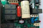
In the photo below, an amplifier assembled according to the diagram in Figure 2:
No voltage is applied to the input of the amplifier, the voltmeter connected to the output shows 2.6V, which is close to the selected value. If you apply a straight polarity voltage to the input (such as in Figure 5), then the output voltage will decrease (the amplifier inverts the signal):

If a reverse polarity voltage is applied to the input, the output voltage will increase but not more than the supply voltage:

The decrease in input voltage, when connected to the source input, is less than the increase in output voltage, which indicates that the input signal is being amplified with inversion. The common emitter circuit produces more power gain than the common base and common emitter circuits, but it produces signal inversion unlike the other two. If it is necessary to amplify the DC power without inversion, then you can cascade the two circuits in Figure 5, but it must be taken into account that the first stage will change the operating mode of the transistor of the second stage, so the resistance of the resistors in the second stage will need to be selected so that this change is as possible less. Also, with a cascade connection, the gain of the entire amplifier will increase (it will be equal to the product of the gain of the first stage by the gain of the second).
This amplifier can be built into any low-power equipment with low-voltage power supply: receivers, walkie-talkies, hearing aids and other similar equipment.
Specifications:
Maximum Output Power (Load 8Ω, 1kHz) = 0.3W
Rated supply voltage (0.3W, 8 ohms) = 3V
THD+N (at maximum output power, 1kHz) = 1 - 1.5%
Schematic diagram of the amplifier:
Device and principle of operation
The amplifier consists of two nodes: the input stage on the transistor T1 and the output push-pull on the transistors T2 - T5. The signal amplified by transistor T1 enters the load R1 and the output stage. The output stage transistors form two so-called "shoulders" of the output stage. Transistors in these "shoulders" of a different structure, which is a prerequisite for this amplifier. Since the KT315 transistor opens with a positive and KT361 with a negative voltage, the “shoulders” of the output stage formed by them amplify only that half-wave of the signal coming from the T1 transistor, which “opens” the transistors that form them. It turns out like this: T3 and T4 amplify the positive half-waves of the signal, T2 and T5 are negative. At the connection point of the emitters of transistors T4 and T5, the signal is combined and fed to the load. Since this amplifier is characterized by step-type distortions, which will inevitably appear during the operation of this amplifier, resistor R2 is turned on to attenuate them. This resistor creates a small bias voltage at the bases of the transistors and attenuates signal distortion.
This amplifier requires careful tuning, namely:
By selecting the resistor R1, the initial quiescent current of the transistors is set (the current flowing through the transistors in the absence of a signal). By selecting this resistor, it is necessary to set the quiescent current at the level of 5 - 7 mA.
By selecting the resistance of the resistor R5, it is necessary to set the voltage at the connection point of the output stage transistors equal to half the supply voltage, that is, 1.5 V.
Possible additions
If the device to which the amplifier is connected does not have a tone control or the signal taken from it is weak, you can assemble a preamplifier.

If there is no need for a tone control, then it can be excluded from the circuit.
On the resistor R4, a passive timbre control HF - LF is assembled with one resistor. Resistor R3 - volume control. All amplification of the signal falls on the transistor. Do not be confused by the lack of a capacitor between the resistor R3 and the collector of the transistor. Everything works and so.
Used parts and possible replacement.
|
Number |
Possible replacement |
|
|
KT3102 a - e, KT312, 315, 316. |
||
|
KT361 a - e. |
||
|
KT315 a - e. |
||
|
KT815, 817 a - c. |
||
|
KT816, 814 a - c. |
This amplifier was assembled by surface mounting, so there is no printed circuit board file. Although drawing a signet for this amplifier is not at all difficult.
After mastering the basics of electronics, a novice radio amateur is ready to solder his first electronic designs. Audio power amplifiers tend to be the most repeatable designs. There are a lot of schemes, each differs in its parameters and design. This article will look at some of the simplest and most fully working amplifier circuits that can be successfully repeated by any radio amateur. The article does not use complex terms and calculations, everything is simplified as much as possible so that there are no additional questions.
Let's start with a more powerful scheme.
So, the first circuit is made on the well-known TDA2003 chip. This is a mono amplifier with an output power of up to 7 watts into a 4 ohm load. I want to say that the standard switching circuit of this microcircuit contains a small number of components, but a couple of years ago I came up with a different circuit on this microcircuit. In this scheme, the number of components is minimized, but the amplifier has not lost its sound parameters. After the development of this circuit, I began to make all my amplifiers for low-power speakers on this circuit.
The circuit of the presented amplifier has a wide range of reproducible frequencies, the supply voltage range is from 4.5 to 18 volts (typical 12-14 volts). The microcircuit is installed on a small heat sink, since the maximum power reaches up to 10 watts.
The microcircuit is capable of operating at a load of 2 ohms, which means that 2 heads with a resistance of 4 ohms can be connected to the amplifier output.
The input capacitor can be replaced with any other, with a capacitance from 0.01 to 4.7 uF (preferably from 0.1 to 0.47 uF), both film and ceramic capacitors can be used. All other components should not be replaced.

Volume control from 10 to 47 kOhm.
The output power of the microcircuit allows it to be used in low-power PC speakers. It is very convenient to use a chip for stand-alone speakers for a mobile phone, etc.
The amplifier works immediately after switching on, it does not need additional adjustment. It is advised to additionally connect the minus power supply to the heat sink. All electrolytic capacitors are preferably used at 25 volts.
The second circuit is assembled on low-power transistors, and is more suitable as a headphone amplifier.

This is probably the highest quality circuit of its kind, the sound is clear, the entire frequency spectrum is felt. With good headphones, it feels like you have a full subwoofer.

The amplifier is assembled on only 3 reverse conduction transistors, as the cheapest option, transistors of the KT315 series were used, but their choice is quite wide.
The amplifier can operate on a low-impedance load, up to 4 ohms, which makes it possible to use the circuit to amplify the signal of a player, radio receiver, etc. A 9 volt battery was used as a power source.
KT315 transistors are also used in the final stage. To increase the output power, you can use KT815 transistors, but then you will have to increase the supply voltage to 12 volts. In this case, the power of the amplifier will reach up to 1 watt. The output capacitor can have a capacitance from 220 to 2200 uF.
The transistors in this circuit do not heat up, therefore, no cooling is needed. When using more powerful output transistors, you may need small heatsinks for each transistor.
And finally - the third scheme. A no less simple, but proven version of the amplifier structure is presented. The amplifier is capable of operating from low voltage up to 5 volts, in which case the output power of the PA will be no more than 0.5 W, and the maximum power when powered by 12 volts reaches up to 2 watts.

The output stage of the amplifier is built on a domestic complementary pair. Adjust the amplifier by selecting the resistor R2. To do this, it is desirable to use a 1 kOhm trimmer. Slowly rotate the knob until the quiescent current of the output stage is 2-5 mA.
The amplifier does not have a high input sensitivity, so it is advisable to use a preamplifier before the input.

A diode plays an important role in the circuit; it is here to stabilize the output stage mode.
The output stage transistors can be replaced with any complementary pair of appropriate parameters, for example, KT816/817. The amplifier can power low-power autonomous speakers with a load resistance of 6-8 ohms.
List of radio elements
| Designation | Type of | Denomination | Quantity | Note | Score | My notepad | |
|---|---|---|---|---|---|---|---|
| Amplifier on a TDA2003 chip | |||||||
| Audio amplifier | TDA2003 | 1 | To notepad | ||||
| C1 | 47uF x 25V | 1 | To notepad | ||||
| C2 | Capacitor | 100 nF | 1 | Film | To notepad | ||
| C3 | electrolytic capacitor | 1uF x 25V | 1 | To notepad | |||
| C5 | electrolytic capacitor | 470uF x 16V | 1 | To notepad | |||
| R1 | Resistor | 100 ohm | 1 | To notepad | |||
| R2 | Variable resistor | 50 kOhm | 1 | From 10 kΩ to 50 kΩ | To notepad | ||
| Ls1 | dynamic head | 2-4 ohm | 1 | To notepad | |||
| Transistor amplifier circuit number 2 | |||||||
| VT1-VT3 | bipolar transistor | KT315A | 3 | To notepad | |||
| C1 | electrolytic capacitor | 1uF x 16V | 1 | To notepad | |||
| C2, C3 | electrolytic capacitor | 1000uF x 16V | 2 | To notepad | |||
| R1, R2 | Resistor | 100 kOhm | 2 | To notepad | |||
| R3 | Resistor | 47 kOhm | 1 | To notepad | |||
| R4 | Resistor | 1 kOhm | 1 | To notepad | |||
| R5 | Variable resistor | 50 kOhm | 1 | To notepad | |||
| R6 | Resistor | 3 kOhm | 1 | To notepad | |||
| dynamic head | 2-4 ohm | 1 | To notepad | ||||
| Transistor amplifier circuit No. 3 | |||||||
| VT2 | bipolar transistor | KT315A | 1 | To notepad | |||
| VT3 | bipolar transistor | KT361A | 1 | To notepad | |||
| VT4 | bipolar transistor | KT815A | 1 | To notepad | |||
| VT5 | bipolar transistor | KT816A | 1 | To notepad | |||
| VD1 | Diode | D18 | 1 | Or any low power | To notepad | ||
| C1, C2, C5 | electrolytic capacitor | 10uF x 16V | 3 | ||||
The KT315 transistor is very popular with beginner radio amateurs of the old school. This bipolar transistor was developed in 1967. The reason for its popularity is its massive use in household radio equipment. It was used both in televisions and in receivers, sound generators. It is easy enough to recognize it among thousands of others because of its unusual body.
Multivibrator on KT315
An excellent scheme for those who are just starting to use a soldering iron and already want to assemble their first device.

Paired with the KT815 transistor, it will help protect other assembled devices from an unforeseen situation or short circuit.
A simple audio amplifier based on KT315 transistors

Amplifier for two channels with a printed circuit board. It will help you understand the basics of assembling amplifiers.
Generator on KT315

Paired with his "brother" KT361, you can assemble a simple sound generator.
Sound simulator

Another sound generator on the legendary KT315.
Color music on transistors

Color music for two LEDs paired with transistors.
Metronome scheme

An interesting pattern for beginners.
temperature sensor

Using semiconductor properties, the ambient temperature can be measured.
Pinout KT315

A complete analogue of the transistor - BFP719.
Schematic Assembly Rules
First, you need to choose a scheme. Choose according to difficulty and experience. Next, you need to make a list of parts, read the diagram. It is better to buy parts in specialized stores than in general sites. Before assembling the circuit, it is imperative to check every detail for serviceability in order to avoid unnecessary errors. The simplest test is with a multimeter in the "dialing" mode. None of the details from the schemes presented above should be "ringed" shortly.
The circuits can be assembled both by surface mounting, and you can make the board yourself. And the golden mean is the circuit board. They are universal, and allow you to assemble most DIP circuits without much difficulty. 
When assembling a circuit, it is best to start with small soldering components. When soldering, do not allow overheating, a maximum of a couple of seconds at the contacts, then you need to evaluate the result of soldering and act according to the situation. Semiconductors are especially sensitive to overheating. Since the KT315 transistors have a plastic case, they have nowhere to give off heat, and you need to solder them as carefully as possible. Another catch is their wide and thin conclusions, which do not tolerate frequent flexion and extension.
After assembly, you need to clean the board, carefully look at all the contacts for cold soldering and unwanted jumpers.
Why doesn't the circuit work?
All diagrams are working. If the device is not working, there are three main reasons:
- Overheating of parts;
- Incorrect assembly of the circuit;
- Bad soldering.
You need to check every step and every stage of the assembly.
Post Views: 1,835
- 03.10.2014
The figure shows the power supply scheme developed by Texas Instruments for a GSM / GPRS module based on the TPS54260 chip. The nominal input voltage in this circuit is 12 V, and the full operating range is 8…40 V. The calculation methodology and test results are described in detail in the “Creating GSM / GPRS Power Supply from TPS54260” document. In the same document, you can find a circuit for a rated voltage ...
- 04.10.2014
There are quite a few circuits of power regulators on thyristors or triacs, where the adjustment is carried out by changing the firing angle. Regulators with such a scheme create interference in the network, so they can only be used with bulky LC filters. In cases where it is not important that the power is given to the load every half-cycle, but it matters ...
- 28.09.2014
A schematic diagram of such a player is shown in the figure. The amplifier is designed to work on 4 speakers (2-front and 2-rear). The rear speakers are two-way, each consists of one elliptical speaker of a sufficiently large diameter and one tweeter. The front channels are simpler - each consists of one full-range speaker. The rear channels have a rise in frequency response at frequencies above ...
- 25.09.2014
The development of nuclear energy and the widespread use of sources of ionizing radiation in various fields of science and technology, as well as their possible appearance in everyday conditions, require familiarization with the properties and methods for detecting alpha, beta and gamma radiation, as well as acquiring relevant knowledge and practical skills in protection from their influence. Assessing and conducting research…
- 21.09.2014
A time relay with a power of not more than 100 W with a delay for turning off the lighting lamp of about 10 minutes can be assembled according to the circuit diagram shown in the figure. The device contains a rectifier bridge VD1-VD4, a trinistor VS1, a control transistor VT1 and a timing unit on a capacitor C1, a zener diode VD2 and a transistor VT2. When closing the contacts of the switch SA1 ...