Hello to all lovers of electronic homemade products. Recently, I quickly made an electronic thermostat with my own hands, the device diagram is very simple. As an actuator, an electromagnetic relay with powerful contacts is used that can withstand currents up to 30 amperes. Therefore, the considered homemade product can be used for various household needs.
According to the scheme below, the thermostat can be used, for example, for an aquarium or for storing vegetables. For someone it can be useful when used in conjunction with an electric boiler, and someone can adapt it for a refrigerator.
Do-it-yourself electronic thermostat, device diagram

As I said, the circuit is very simple, contains a minimum of inexpensive and common radio components. Typically, thermostats are built on a comparator chip. Because of this, the device becomes more complicated. This homemade product is built on an adjustable zener diode TL431:

Now let's talk more about the details that I used.
Device details:
- 12 volt step down transformer
- Diodes; IN4007, or others with similar specifications 6 pcs.
- electrolytic capacitors; 1000 microns, 2000 microns, 47 microns
- Chip stabilizer; 7805 or other 5 volt
- Transistor; KT 814A, or another p-n-p with a collector current of at least 0.3 A
- Adjustable zener diode; TL431 or Soviet KR142EN19A
- Resistors; 4.7 kΩ, 160 kΩ, 150 ohm, 910 ohm
- Variable resistor; 150 Kom
- Thermistor as a sensor; about 50 kw with negative tks
- Light-emitting diode; any with the lowest current consumption
- Relay electromagnetic; any 12 volt with a current consumption of 100 mA or less
- Button or toggle switch; for manual control
How to make a thermostat with your own hands
The burned-out electronic counter Granit-1 was used as a case. The board on which all the main radio components are located is also from the meter. Inside the case fit a power supply transformer and an electromagnetic relay:


As a relay, I decided to use an automotive one, which can be purchased at any car dealer. Coil operating current approximately 100 milliamps:


Since the adjustable zener diode is low-power, its maximum current does not exceed 100 milliamps, it will not work to directly connect the relay to the zener diode circuit. Therefore, I had to use a more powerful transistor KT814. Of course, the circuit can be simplified if a relay is used, in which the current through the coil will be less than 100 milliamps, for example, or SRA-12VDC-AL. Such relays can be connected directly to the zener diode cathode circuit.
I'll talk a little about the transformer. As which I decided to use non-standard. I have a voltage coil from an old induction electric energy meter lying around:

As you can see in the photo, there is free space for the secondary winding, I decided to try winding it and see what happens. Of course, the cross-sectional area of \u200b\u200bthe core is small, and, accordingly, the power is small. But for this temperature controller, this transformer is enough. According to my calculations, I got 45 turns per 1 volt. To get 12 volts at the output, you need to wind 540 turns. To fit them, I used a wire with a diameter of 0.4 mm. Of course, you can use a ready-made one with an output voltage of 12 volts or an adapter.
As you noticed, the circuit has a 7805 stabilizer with a stabilized output voltage of 5 volts, which feeds the control output of the zener diode. Thanks to this, the temperature controller turned out with stable characteristics that will not change from changes in the supply voltage.
As a sensor, I used a thermistor, which at room temperature has a resistance of 50 kΩ. When heated, the resistance of this resistor decreases:

To protect it from mechanical influences, I used heat-shrinkable tubes:


The place for the variable resistor R1 was found on the right side of the thermostat. Since the axis of the resistor is very short, I had to solder a flag on it, for which it is convenient to turn. On the left side, I placed the manual control toggle switch. With it, it is easy to control the operating state of the device, while not changing the set temperature:


Despite the fact that the terminal block of the former electric meter is very bulky, I did not remove it from the case. It clearly includes a plug from any device, such as an electric heater. By removing the jumper (yellow on the right in the photo) and turning on the ammeter instead of the jumper, you can measure the current supplied to the load:

Now it remains to calibrate the thermostat. For this we need . It is necessary to connect both sensors of the device together with electrical tape:

Use a thermometer to measure the temperature of various hot and cold objects. Using a marker, apply a scale and markings on the thermostat, the moment the relay is turned on. I got from 8 to 60 degrees Celsius. If someone needs to shift the operating temperature in one direction or another, this is easy to do by changing the values of the resistors R1, R2, R3:

So we made an electronic thermostat with our own hands. Outwardly it looks like this:

In order not to see the inside of the device, through the transparent cover, I covered it with adhesive tape, leaving a hole for the HL1 LED. Some radio amateurs who decide to repeat this scheme complain that the relay turns on, not very clearly, as if rattling. I did not notice anything, the relay turns on and off very clearly. Even with a slight change in temperature, no chatter occurs. If, nevertheless, it arises, it is necessary to select more accurately the capacitor C3 and the resistor R5 in the base circuit of the KT814 transistor.
The assembled thermostat according to this scheme turns on the load when the temperature drops. If someone, on the contrary, needs to turn on the load when the temperature rises, then you need to swap the sensor R2 with resistors R1, R3.
Compliance with the temperature regime is a very important technological condition not only in production, but also in everyday life. Having such a great importance, this parameter must be regulated and controlled by something. A huge number of such devices are produced, having many features and parameters. But making a thermostat with your own hands is sometimes much more profitable than buying a ready-made factory analogue.
Create your own thermostat
General concept of temperature controllers
Devices that fix and simultaneously regulate the set temperature value are more common in production. But they also found their place in everyday life. To maintain the necessary microclimate in the house, thermostats for water are often used. With their own hands they make such devices for drying vegetables or heating an incubator. Such a system can find its place anywhere.
In this video, we will learn what a temperature controller is:
In fact, most thermostats are only part of the overall scheme, which consists of the following components:
- A temperature sensor that measures and fixes, as well as transmits the information received to the controller. This happens due to the conversion of thermal energy into electrical signals that are recognized by the device. A resistance thermometer or a thermocouple can act as a sensor, which in their design have a metal that reacts to temperature changes and changes its resistance under its influence.
- The analytical block is the regulator itself. It receives electronic signals and reacts depending on its functions, after which it transmits a signal to the actuator.
- An actuator is a kind of mechanical or electronic device that, when receiving a signal from the unit, behaves in a certain way. For example, when the set temperature is reached, the valve will shut off the coolant supply. Conversely, as soon as the readings fall below the set values, the analytical unit will give a command to open the valve.
These are the three main parts of the system for maintaining the set temperature parameters. Although, in addition to them, other parts, such as an intermediate relay, may participate in the circuit. But they perform only an additional function.
Principle of operation
The principle by which all regulators work is the removal of a physical quantity (temperature), the transfer of data to the control unit circuit, which decides what needs to be done in a particular case.
If you make a thermal relay, then the simplest option will have a mechanical control circuit. Here, with the help of a resistor, a certain threshold is set, upon reaching which a signal will be given to the actuator.
To get additional functionality and the ability to work with a wider temperature range, you will have to embed a controller. This will also help increase the life of the device.
In this video you can see how to make a thermostat for electric heating yourself:
Homemade temperature controller
There are actually a lot of schemes for making a thermostat yourself. It all depends on the area in which such a product will be used. Of course, creating something too complex and multifunctional is extremely difficult. But a thermostat that can be used to heat an aquarium or dry vegetables for the winter can be created with a minimum of knowledge.
The simplest circuit
The simplest do-it-yourself thermal relay circuit has a transformerless power supply, which consists of a diode bridge with a zener diode connected in parallel, which stabilizes the voltage within 14 volts, and a quenching capacitor. You can also add a 12 volt stabilizer here if you wish.
 Creating a thermostat does not require much effort and money investments
 The whole circuit will be based on a TL431 zener diode, which is controlled by a divider consisting of a 47 kΩ resistor, a 10 kΩ resistance and a 10 kΩ thermistor acting as a temperature sensor. Its resistance decreases with increasing temperature. It is better to select a resistor and resistance in order to achieve the best operation accuracy.
The process itself is as follows: when a voltage of more than 2.5 volts is formed on the control contact of the microcircuit, it will make an opening, which will turn on the relay, applying a load to the actuator.
How to make a thermostat for an incubator with your own hands, you can see in the video below:
Conversely, when the voltage becomes lower, the microcircuit will close and the relay will turn off.
To avoid rattling of the relay contacts, it is necessary to select it with a minimum holding current. And in parallel with the inputs, you need to solder a 470 × 25 V capacitor.
When using an NTC thermistor and microcircuits that have already been in use, you should first check their performance and accuracy.
Thus, turns out to be the simplest device temperature control. But with the right components, it performs excellently in a wide range of applications.
Indoor device
Such thermostats with a do-it-yourself air temperature sensor are optimally suited for maintaining the specified microclimate parameters in rooms and containers. It is fully capable of automating the process and controlling any heat emitter from hot water to heating elements. At the same time, the thermal switch has excellent operational data. And the sensor can be both built-in and remote.
Here, the thermistor, indicated in the diagram R1, acts as a temperature sensor. The voltage divider includes R1, R2, R3 and R6, the signal from which is fed to the fourth pin of the operational amplifier microcircuit. The fifth pin DA1 receives a signal from the divider R3, R4, R7 and R8.
The resistance of the resistors must be selected in such a way that at the lowest possible temperature of the measured medium, when the resistance of the thermistor is maximum, the comparator is positively saturated.
The output voltage of the comparator is 11.5 volts. At this time, the transistor VT1 is in the open position, and the relay K1 turns on the actuator or intermediate mechanism, as a result of which heating begins. The ambient temperature rises as a result, which lowers the resistance of the sensor. At input 4 of the microcircuit, the voltage begins to rise and, as a result, exceeds the voltage at pin 5. As a result, the comparator enters a negative saturation phase. At the tenth output of the microcircuit, the voltage becomes approximately 0.7 Volts, which is a logical zero. As a result, the transistor VT1 closes, and the relay turns off and turns off the actuator.
On the LM 311 chip
Such a do-it-yourself thermocontroller is designed to work with heating elements and is able to maintain the set temperature parameters within 20-100 degrees. This is the safest and most reliable option, since its operation uses galvanic isolation of the temperature sensor and control circuits, and this completely eliminates the possibility of electric shock.
Like most similar circuits, it is based on a DC bridge, in one arm of which a comparator is connected, and in the other - a temperature sensor. The comparator monitors the circuit mismatch and reacts to the state of the bridge when it passes the balance point. At the same time, he also tries to balance the bridge with the help of a thermistor, changing its temperature. And thermal stabilization can occur only at a certain value.
Resistor R6 sets the point at which a balance should be formed. And depending on the temperature of the environment, the thermistor R8 can enter into this balance, which allows you to adjust the temperature.
In the video you can see an analysis of a simple thermostat circuit:
If the temperature set by R6 is lower than required, then the resistance on R8 is too high, which reduces the current on the comparator. This will cause current to flow and open the sevenstor VS1 which will turn on the heating element. This will be indicated by an LED.
As the temperature rises, the resistance R8 will decrease. The bridge will tend to the point of balance. On the comparator, the potential of the inverse input smoothly decreases, and on the direct input it increases. At some point, the situation changes, and the process occurs in the opposite direction. Thus, the do-it-yourself thermocontroller will turn on or off the actuator, depending on the resistance R8.
If there is no LM311 available, then it can be replaced with a domestic chip KR554CA301. It turns out a simple do-it-yourself thermostat with minimal cost, high accuracy and reliability.
Necessary materials and tools
By itself, the assembly of any circuit of the electric temperature controller does not take much time and effort. But to make a thermostat, you need minimal knowledge in electronics, a set of parts according to the diagram and a tool:
- Pulse soldering iron. You can use the usual, but with a thin sting.
- Solder and flux.
- Printed circuit board.
- Acid to etch the tracks.
Advantages and disadvantages
Even a simple do-it-yourself thermostat has a lot of advantages and positive aspects. It is not necessary to talk about factory multifunctional devices at all.
Temperature controllers allow:
- Maintain a comfortable temperature.
- Save energy resources.
- Do not involve a person in the process.
- Follow the technological process, improving the quality.
Among the shortcomings can be called the high cost of factory models. Of course, this does not apply to homemade devices. But the production ones, which are required when working with liquid, gaseous, alkaline and other similar media, have a high cost. Especially if the device must have many functions and capabilities.
The described electrical circuit of the electronic thermostat for the refrigerator changes the duration of the pause in the operation of the compressor, which depends on the internal temperature.
Description of the operation of the thermostat for the refrigerator
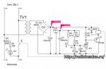
The electrical circuit (Fig. 1.35) contains a generator on the DD1 chip, keys on the radio elements DD2.2, DD2.3 and an inverter on the DD2.1 element.
The generator on the K176IE5 chip has switchable RC circuits (Rl, R3, Cl and R2, R4, C2). modification of the timing circuits is performed by keys on the K561KT3 chip. Key management begins with signals from the output of the fifteenth bit (pin 5) of the signal divider DD1.
At a high voltage at the output 5 to the internal log. one RC circuit (R2, R4, C2) is connected to the elements of the DD1 chip. At low voltage, the electrical signal is reversed by the inverter on the element DD2.1 and, through the key DD2.2, another circuit is connected (Rl, R3, Cl). To change the refrigerator thermostat, the resistance R4 can have a value of 100 kilo-ohms or more.

When the temperature in the refrigerator dropped to 0 degrees, the MMT4 brand thermistor with a resistance of 220 kilo-ohms had a resistance of 400 kOhm. Since the thermistor is connected in the circuit that determines the duration of the pause, the lower the temperature in the refrigerator compartment, the greater the moment of pause in the operation of the refrigerator compressor.
Therefore, the temperature is adjusted by changing the duration of the pause in the operation of the refrigerator compressor by the resistance R3. The control impulse, through the key on the transistor VT1, turns on the intermediate electric relay Kl, which turns on a more powerful relay. Intermediate electric relay brand RES6, RES49.
The K561KT3 chip can be changed to K176KT1. Switch SA1 is needed to enable the continuous operation of the compressor after defrosting the refrigerator. The printed circuit board of the electric relay is shown in Figure 1.36, and from the side of the installation of radio components, Figure 1.37.


The dimensions of the board are limited by the size of the electric relay for 220 V. Rectifier diodes and filter capacitances are located on the board. Thermistor R3 is soldered to a thin wire of the MGTF brand and placed in a freezer.
Resistance R4 and switch SA1 are placed close to the plastic side cover of the relay. The alternating voltage going to the electrical circuit must be such that the rectified voltage is not more than 9 V. At a lower voltage. the K176IE5 chip can still work, however, at voltage. more than 9V, it may not work.
If you need an extremely low frequency generator with separate adjustment of the duration of high and low levels, then the resistance R3 can be replaced by a potentiometer up to 3 MΩ. The frequency is approximately calculated by the formula F = 0.7/RC.
When calculating the duration, it should be remembered that the moment of work or pause will be equal to half the calculated one, since only a part of the period is taken - either a high level or a low one.
Simple refrigerator thermostat
DIYMake a Simple Refrigerator Thermostat Circuit
Want to make an accurate electronic thermostat for your refrigerator? The solid state thermostat circuit described in this article will surprise you with its "cool" performance.
Introduction
A device, once built and integrated with any suitable device, will instantly begin to exhibit improved system control, saving energy as well as extending the life of the device. Conventional refrigeration thermostats are expensive and not very accurate. Moreover, they are subject to wear and therefore are not permanent. A simple and efficient electronic refrigeration thermostat is discussed here.
A thermostat, as we all know, is a device that is able to perceive a certain set temperature level and turn off or switch an external load. Such devices may be electromechanical types or more complex electronic types.
Thermostats are usually associated with air conditioning, refrigeration and water heating devices. For such applications, the device becomes an important part of the system, without which the device can reach and start working in extreme conditions and eventually get damaged.
Adjusting the control switch provided in the above devices ensures that the thermostat turns off the power to the device after the temperature crosses the required limit and switches back as soon as the temperature returns to the lower threshold.
Thus, the temperature inside refrigerators or room temperature through the air conditioner is maintained in favorable ranges.
The refrigeration thermostat circuit idea presented here can be used externally above a refrigerator or any similar device to control its operation.
Their operation can be controlled by attaching a thermostat sensing element to an external heat sink, usually located behind most refrigerant units that use Freon.
The design is more flexible and wider than built-in thermostats and is able to show better efficiency. The circuit can easily replace conventional low-tech designs, and besides, it is much cheaper compared to them.
Let's understand how the circuit works:
Circuit Description
A simple refrigerator thermostat circuit
The diagram shows a simple circuit built around IC 741 which is basically configured as a voltage comparator. It uses a lower power transformer to make the circuit compact and solid state.
The bridge configuration containing R3, R2, P1 and NTC R1 at the input forms the main sensing elements of the circuit.
The inverting input of IC is clamped to half the supply voltage using the voltage divider network R3 and R4.
This eliminates the need to provide dual power to the IC and the circuit can provide optimal results even with a single supply voltage.
The reference voltage to the non-inverting input of IC is clamped across a given P1 with respect to NTC (Negative Temperature Coefficient).
In the event that the temperature under control tends to drift above the desired levels, the NTC resistance drops and the potential at the non-inverting input of IC crosses the set value.
This instantly switches the output of the IC, which in turn switches the output stage containing the transistor, the triax network, turning off the load (heating or cooling system) until the temperature reaches a lower threshold.
The feedback resistance R5 to some extent helps to induce hysteresis in the circuit, an important parameter without which the circuit can spin rapidly in response to sudden changes in temperature.
Once the assembly is completed, setting up the circuit is very simple and is done with the following points:
REMEMBER EXTERNAL CIRCUIT BASED ON CONSTANT SOURCE POTENTIAL, CAUTION WARNING IS WARNED TO AGAINST TESTING AND INSTALLATION PROCEDURES. THE USE OF A WOOD PLANK OR ANY OTHER INSULATING MATERIAL ON YOUR FOOT IS STRONGLY RECOMMENDED; ALSO USE ELECTRIC TOOLS WHICH SHOULD BE INSULATED NEAR THE SITE.
How to set up this electronic refrigeration circuit thermostat You will need a sample heat source finely adjusted to your desired cutoff threshold level for the thermostat circuit.
Turn on the circuit and enter and attach the above heat source to the NTC.
Now adjust the preset so that the output just switches (the output LED lights up). Remove the heat source from the NTC, depending on the hysteresis of the circuit, the output should turn off within a few seconds.
Repeat the procedure many times to confirm its correct functioning.
This completes the setup of this refrigeration thermostat and is ready to be integrated with any refrigerator or similar device for precise and constant regulation of its operation.
Parts list
R2 = Preset 10KR3,
R9=56ohm/1watt
C1 = 105 / 400V
C2 = 100uF / 25V
Z1 = 12V, 1W zener diode
* option via optocoupler, added switch and diode bridge to the power supply

How to create an automatic refrigerator temperature controller circuit
The idea for this circuit was suggested to me by one of the keen readers of this blog, Mr. Gustavo. I have posted one similar circuit for an automatic refrigerator thermostat, however the circuit was designed to detect the higher temperature level available at the back of the refrigerator grille.
Introduction
Mr. Gustavo didn't quite get the idea and he asked me to design a refrigerator thermostat circuit that could sense cold temperatures inside the refrigerator rather than hot temperatures at the back of the refrigerator.
So with some effort I could find a real Fridge Temperature Controller CHAIN DIAGRAM, let's explore this idea with the following points:
How circuits function
The concept is not very new nor unique, it is the usual comparator concept that has been included here.
IC 741 has been rigged in standard comparator mode and also as a non-inverting amplifier circuit.
The NTC thermistor becomes the main sensing component and is specially responsible for cold temperature sensitivity.
NTC stands for Negative Temperature Coefficient, which means that the thermistor's resistance will increase as the temperature around it drops.
It should be noted that the NTC must be rated according to these specifications, otherwise the system will not function properly.
The preset P1 is used to set the trip point of the IC.
When the temperature inside the refrigerator drops below the threshold level, the thermistor resistance becomes high enough and reduces the voltage on the inverting pin below the level of the non-inverting pin voltage.
This instantly makes the IC output high, activating the relay and turning off the refrigerator compressor.
P1 should be set so that the output of the op-amp goes high at zero degrees Celsius.
The slight hysteresis introduced by the circuit comes as a boon, or rather a blessing in disguise, because it causes the circuit to not switch quickly at threshold levels, but only reacts after the temperature has risen about a couple of degrees above the shutdown level.
For example, suppose if the trigger level is set to zero, the IC will turn off the relay at that point, and the refrigerator compressor will also be turned off, the temperature inside the refrigerator will now start to rise, but the IC will not switch immediately, but maintains its position as long as the temperature will not rise to at least 3 degrees Celsius above zero. 
If you have further questions regarding this automatic refrigerator temperature controller circuit, you can express the same through your comments.
RP1, RP2 regulation can be set temperature control points, 555 time Schmitt circuit inversion circuit, using relays to achieve automatic control.

| Updated 01 Apr 2018. Created 29 Mar 2018 | |||||||||
From a technological point of view, the design of the refrigerator is a combination of such components as a thermoregulation system, a start relay and a blower compressor.
All nodes may be faulty, while different causes may have the same symptoms. Very often, when a starting relay is suspected during repair, the reason is a breakdown of the thermostat. To understand how an ordinary refrigerator.
Temperature controller with spiral sensor
What is a thermostat and why is it needed
When the device ceases to function adequately, the symptoms may be the following:
- the motor runs continuously, the refrigeration device does not turn off;
- a “snow coat” (deposits of ice and hoarfrost) is found on the walls of the chamber, the injection is too active, the circulation of freon is increased and the refrigerator freezes too much;

Snow coat: a sure sign of a malfunction
- it is warm in the refrigerator compartment, the more items you load inside, the worse the space cools.
- after turning off, the motor does not start immediately (it keeps the temperature for a long time and does not restart).
To correct the situation, you should turn off the device from the network, perform a complete defrosting. The contents of the chambers should be removed, then turn on the refrigerator and switch the temperature in the regulator to full maximum (minimum temperature). A thermometer should be placed inside the refrigerator (do not use liquid ones, electronic ones are best). If the thermostat is functioning, then as soon as the thermometer shows the readings that you have set, the refrigerator will turn off. If, after reaching the temperature, the motor continues to work and cool the chambers, then the thermostat is faulty.
In conditions of constant adjustments, the temperature inside the chamber is constantly changing, the rate of these changes depends on the sensitivity level of the thermostat.

Thermostat device
Temperature controllers of all refrigeration systems (including household appliances) are manometric type devices. They function due to changes in fill pressure. Pressure changes due to temperature differences. Some modern refrigerators contain an electronic thermostat - a much more advanced device that allows you to more accurately record temperature changes and turn off / turn on the compressor relay.
Temperature controllers are mechanisms containing a lever system and a set of contacts through which the device is included in the general electrical wiring.
The temperature regulator is based on the so-called bellows - an element sensitive to temperature changes, which, with the help of a spring, acts on the general electrical circuit. Thus, when the temperature changes, the bellows transmits a signal to the spring, the spring to the lever, the lever to the main mechanism, the mechanism acts on the overall electronic system. Of course, also, the regulator has a special gasket that acts as an insulator of the internal components of the thermostat from the external environment (primarily from humidity). The regulator is also filled with a special liquid (chloromethyl) inside.
The most basic, and where to start work, is to check the thermostat. A sign of a malfunction or impending breakdown is excessive freezing of the refrigerator, or, conversely, the device has completely stopped heating. This means that the regulator "does not understand" the temperature well, i.e. it can work, but the range in which it detects temperature has changed. You set the fridge to 4 degrees and it turns off at +15? This means that the thermostat "thinks" that +15 is 4 degrees and therefore a false signal appears on the refrigerator. There are two ways to check:
Method number 1 - directly
Leave the thermostat inside the refrigerator. Finding the two wires that go into it, disconnect them carefully (so that you can easily put them back in place later) and connect them together. Be careful! The wires carry high voltage. All operations with wires should be done only with the engine off.

Two wires coming from the regulator
This method is good if . He fully checks the thermostat, since all temperature limits are no longer relevant.
Method #2: Checking the Bellows
This method allows you to check the regulator without resorting to its removal and disassembly. However, some basic knowledge of component design is required. Near the small axis on which the adjustment knob itself is attached, you should find a plate, you need to move and click it.

Dismantled thermostat
If the plate is fixed “tightly” and cannot be shifted (there are no clicks), then the regulator is disabled.
Method number 3 - tester check
The main method used by most masters is to check with a tester (multimeter). To do this, the thermostat must be removed (before replacement, it will need to be dismantled in any case). The multimeter should be set to "resistance" mode; the setting should be minimal (set to minimum).

Checking with a multimeter (tester)
There are cases (however, extremely rarely) that the thermostat functions properly in a dismantled state, but refuses to function inside. This is due to a rare malfunction that may be related to the temperature regime - in the cold it stops working, and at room temperature it does not open the circuit. In order to test it, you should put the part in a glass of very cold water. A few minutes in the water, and he is ready for diagnosis. If the number “1” (breakdown) appears on the tester screen (in the circuit ringing mode), then the regulator is faulty, if “0”, then the part is working.
Safety rules to follow when checking
A refrigerator is a large household appliance that requires high voltage to operate. There are three main threats that potentially exist if you decide to repair your refrigerator:
- electric shock (high voltage is on the contacts of the relay, thermostat, on the compressor windings);
- electric shock (short circuit inside the electrical wiring of the refrigeration device, as a result of contact with open parts of the wiring on the metal case);
- frostbite due to skin contact with refrigerant.
Anyone who decides to repair the thermostat (or any other component of the refrigerator) must take serious precautions. Work should not be carried out while the refrigerator is plugged in: be sure to turn off the power to the device.
As a result (or in the process) of repair work, wiring contacts are formed that should be connected to each other. All connections must be properly insulated. It is necessary to continuously check the presence of voltage on all surfaces capable of conducting current - the case, the internal elements of the refrigerator compartment, etc.).
All tools (screwdrivers, pliers, multimeter terminals) must have insulated handles.