Power supply 1-30V for LM317 + 3 x TIP41C
or 3 x 2SC5200.
The article discusses a simple regulated power supply circuit implemented on the LM317 stabilizer microcircuit, which controls powerful three NPN transistors connected in parallel. The range of adjustment of the output voltage is 1.2 ... 30 Volts with a load current of up to 10 Amperes. TIP41C transistors in TO220 package are used as powerful outputs, their collector current is 6 Amperes, power dissipation is 65 watts. The schematic diagram of the power supply is shown below:

As outputs, you can also use TIP132C, TO220 package, collector current of these transistors is 8 Amperes, power dissipation is 70 watts according to the datasheet.
The pinout of the TIP132C, TIP41C transistors is as follows:

The layout of the terminals for the adjustable stabilizer LM317:

The TO220 transistors are soldered directly onto the PCB and attached to one common heatsink using mica, thermal paste, and grommets. But you can also use transistors in the TO-3 package, from the imported ones, for example, 2N3055 are suitable, the collector current of which is up to 15 Amperes, the power dissipation is 115 W, or the transistors of domestic production KT819GM, they are 15 Amperes with a dissipated power of 100 Watt. In this case, the leads of the transistors are connected to the board with wires.
Alternatively, you can consider the use of imported 15-ampere TOSHIBA 2SC5200 transistors with a power dissipation of 150 watts. It was this transistor that I used when reworking the KIT-set of the power supply unit purchased at Aliexpress.
In the schematic diagram, the terminals PAD1 and PAD2 are intended for connecting an ammeter, the input voltage from the rectifier (diode bridge), X2-1 (-) and X2-2 (+) is applied to the terminals X1-1 (+) and X1-2 (-) these are the output terminals of the power supply, a voltmeter is connected to the JP1 terminal block.
The first version of the printed circuit board is designed for the installation of power transistors in the TO220 package, the LAY6 format is as follows:
Photo-view of the LAY6 format board:
The second version of the printed circuit board for the installation of transistors of the 2SC5200 type, the view of the LAY6 format is below:
Photo-view of the second version of the printed circuit board of the power supply:
The third version of the printed circuit board is the same, but without the diode assembly, you will find it in the archive with the rest of the materials.
List of elements of the regulated power supply circuit on the LM317:
Resistors:
R1 - 5K potentiometer - 1 pc.
R2 - 240R 0.25W - 1 pc.
R3, R4, R5 - ceramic resistors 5W 0R1 - 3 pcs.
R6 - 2K2 0.25W - 1 pc.
Capacitors:
C1, C2 - 4700 ... 6800mF / 50V - 2 pcs.
C3 - 1000 ... 2200mF / 50V - 1 pc.
С4 - 150 ... 220mF / 50V - 1 pc.
C5, C6, C7 - 0.1mF = 100n - 3 pcs.
Diodes:
D1 - 1N5400 - 1 pc.
D1 - 1N4004 - 1 pc.
LED1 - LED - 1 pc.
Diode assembly - I did not have assemblies for a slightly lower current available, so the board was drawn using KBPC5010 (50 Amperes) - 1 pc.
Transistors, microcircuits:
IC1 - LM317MB - 1 pc.
Q1, Q2, Q3 - TIP132C, TIP41C, KT819GM, 2N3055, 2SC5200 - 3 pcs.
Rest:
Bolt-on 2 Pin Connectors (input, output, ammeter) - 3 pcs.
Connector 2 Pin 2.54mm (LED regulating variable) - 2 pcs.
In principle, the connectors can be omitted.
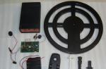
Impressive radiator for weekends - 1 pc.
Transformer, secondary for 22 ... 24 Volts of alternation, capable of running a current of the order of 10 ... 12 Amperes.
The size of the archive file with materials on the power supply unit on the LM317 10A is 0.6 Mb.
It makes sense not only for a keen radio amateur to make a power supply unit with your own hands. A homemade power supply unit (PSU) will create convenience and save a considerable amount also in the following cases:
- For powering low-voltage power tools, in order to save the resource of an expensive rechargeable battery (accumulator battery);
- For the electrification of premises that are especially dangerous in terms of the degree of electric shock: basements, garages, sheds, etc. When powered by alternating current, its large value in low-voltage wiring can interfere with household appliances and electronics;
- In design and creativity for accurate, safe and waste-free cutting of foam plastic, foam rubber, low-melting plastics with heated nichrome;
- In lighting design - the use of special power supplies will extend the life of the LED strip and obtain stable lighting effects. Power supply of underwater illuminators, etc., from a household electrical network is generally unacceptable;
- For charging phones, smartphones, tablets, laptops away from stable power sources;
- For electroacupuncture;
- And many other goals not directly related to electronics.
Acceptable simplifications
Professional PSUs are designed to power loads of any kind, incl. reactive. Precision equipment is among the potential consumers. The preset voltage of the pro-PSU must be maintained with the highest accuracy for an indefinitely long time, and its design, protection and automation must allow operation by unqualified personnel in difficult conditions, for example. biologists to power their devices in a greenhouse or on an expedition.
An amateur laboratory power supply unit is free from these restrictions and therefore can be significantly simplified while maintaining quality indicators sufficient for their own use. Further, through also simple improvements, it is possible to obtain a special-purpose power supply unit from it. What we are going to do now.
Abbreviations
- Short circuit - short circuit.
- XX - idle, i.e. sudden disconnection of the load (consumer) or an open circuit in its circuit.
- KSN - voltage stabilization coefficient. It is equal to the ratio of the change in the input voltage (in% or times) to the same output voltage at a constant consumption current. Ex. the mains voltage dropped "to full", from 245 to 185V. Relative to the norm of 220V, this will be 27%. If the VSD of the PSU is equal to 100, the output voltage will change by 0.27%, which at its value of 12V will give a drift of 0.033V. For amateur practice, more than acceptable.
- PPI is a source of unstabilized primary voltage. It can be a transformer on iron with a rectifier or a pulse mains voltage inverter (IIN).
- IIN - operate at an increased (8-100 kHz) frequency, which allows the use of lightweight compact transformers on ferrite with windings of several or several tens of turns, but they are not without drawbacks, see below.
- RE is a regulating element of a voltage stabilizer (CH). Maintains the specified value at the output.
- ION - a source of reference voltage. Sets its reference value, according to which, together with feedback signals of the OS, the control unit CU acts on the RE.
- SNN - continuous voltage stabilizer; simply "analog".
- ISN - pulse voltage regulator.
- UPS is a switching power supply.
Note: both SNN and IIN can operate both from the IIN of industrial frequency with a transformer on iron, and from the IIN.
About computer power supplies
UPSs are compact and economical. And in the closet, many have a power supply unit from an old computer, morally outdated, but quite serviceable. So, is it possible to adapt a switching power supply from a computer for amateur / work purposes? Unfortunately, a computer UPS is a highly specialized device and the possibilities of its use in everyday life / at work are very limited:

To use a UPS converted from a computer, it is advisable for an ordinary amateur, perhaps, only to power a power tool; see below about this. The second case is if an amateur is engaged in PC repair and / or creation of logic circuits. But then he already knows how to adapt the power supply from the computer for this:
- Load the main channels + 5V and + 12V (red and yellow wires) with nichrome coils at 10-15% of the rated load;
- Green soft start wire (with a low-current button on the front panel of the system unit) pc on short-circuit to common, i.e. on any of the black wires;
- Switch on / off mechanically, with a toggle switch on the rear panel of the power supply unit;
- With a mechanical (iron) I / O "duty room", i.e. independent power supply of + 5V USB ports will also be turned off.
Get down to business!
Due to the shortcomings of the UPS, plus their fundamental and circuitry complexity, we will only at the end consider a couple of such, but simple and useful ones, and talk about the method for repairing IIN. The main part of the material is devoted to SNV and IIT with power frequency transformers. They allow a person who has just picked up a soldering iron to build a PSU of a very high quality. And having it on the farm, it will be easier to master the technique "thinner".
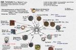
IIT
Let us first consider the IIT. We will leave the impulse ones in more detail until the section on repair, but they have something in common with the "iron" ones: a power transformer, a rectifier and a ripple suppression filter. Together, they can be implemented in various ways in accordance with the purpose of the power supply unit.

Pos. 1 in Fig. 1 - half-wave (1P) rectifier. The voltage drop across the diode is the smallest, approx. 2B. But the ripple of the rectified voltage - with a frequency of 50 Hz and "ragged", ie. with intervals between pulses, therefore, the capacitor of the ripple filter Cf should be 4-6 times larger than in other circuits. The use of a power transformer Tr in terms of power is 50%, since only 1 half-wave is rectified. For the same reason, an imbalance of the magnetic flux occurs in the magnetic circuit Tr and the network "sees" it not as an active load, but as an inductance. Therefore, 1P rectifiers are used only at low power and where there is no other way, for example. in IIN on blocking generators and with a damper diode, see below.
Note: why 2V, and not 0.7V, at which the p-n junction in silicon opens? The reason is the through current, about which see below.
Pos. 2 - 2-half-cycle with a midpoint (2PS). Losses on diodes are the same as before. case. The ripple is 100 Hz solid, so Sph needs the smallest possible. Use of Tr - 100% Disadvantage - double copper consumption for the secondary winding. In the days when rectifiers were made on kenotron lamps, this did not matter, but now it is decisive. Therefore, 2PS is used in low-voltage rectifiers, mainly of increased frequency with Schottky diodes in UPS, however, 2PS does not have fundamental power limitations.
Pos. 3 - 2-half-period bridge, 2RM. Losses on diodes - doubled in comparison with pos. 1 and 2. The rest is the same as in 2PS, but copper for the secondary needs almost half as much. Almost - because several turns have to be completed in order to compensate for the losses on a pair of "extra" diodes. The most common circuit for voltage from 12V.
Pos. 3 - bipolar. The "bridge" is depicted conventionally, as is customary in schematic diagrams (get used to it!), And rotated 90 degrees counterclockwise, but in fact it is a pair of 2PS connected in different polarities, as can be clearly seen further in Fig. 6. Copper consumption as in 2PS, diode losses as in 2PM, the rest as in both. It is built mainly to power analog devices that require voltage symmetry: Hi-Fi UMZCH, DAC / ADC, etc.
Pos. 4 - bipolar according to the parallel doubling scheme. Gives, without additional measures, increased voltage symmetry, because secondary asymmetry is excluded. The use of Tr is 100%, the ripple is 100 Hz, but torn, therefore, Sph needs double the capacity. Losses on diodes are approximately 2.7V due to mutual exchange of through currents, see below, and at a power of more than 15-20 W they increase sharply. They are built mainly as low-power auxiliary for independent power supply of operational amplifiers (OA) and other low-power analog units, but demanding on the quality of power supply.
How to choose a transformer?
In a UPS, the entire circuit is most often clearly tied to the size (more precisely, to the volume and cross-sectional area Sс) of the transformer / transformers, since the use of subtle processes in ferrite makes it possible to simplify the circuit with its greater reliability. Here "somehow in its own way" comes down to the exact observance of the developer's recommendations.
A transformer on iron is chosen taking into account the characteristics of CHN, or is consistent with them when calculating it. The voltage drop across the RE Ure should not be taken less than 3V, otherwise the SVR will drop sharply. With an increase in Ure, the KCH slightly increases, but the power dissipated by the RE grows much faster. Therefore, Ure take 4-6 V. To it we add 2 (4) V losses on the diodes and the voltage drop across the secondary winding Tr U2; for a power range of 30-100 W and voltages of 12-60 V, we take it 2.5 V. U2 arises mainly not on the ohmic resistance of the winding (it is generally negligible for powerful transformers), but as a result of losses due to magnetization reversal of the core and the creation of a stray field. Simply, part of the network energy, "pumped" by the primary winding into the magnetic circuit, evaporates into world space, which is taken into account by the value of U2.
So, we counted, for example, for a bridge rectifier, 4 + 4 + 2.5 = 10.5V excess. We add it to the required output voltage of the PSU; let it be 12V, and divide by 1.414, we get 22.5 / 1.414 = 15.9 or 16V, this will be the lowest allowable voltage of the secondary winding. If Tr is factory-made, we take 18V from the standard range.
Now the secondary current is used, which, of course, is equal to the maximum load current. Let us need 3A; multiply by 18V, it will be 54W. We have obtained the overall power Tr, Pg, and we will find the passport P by dividing Pg by the efficiency Tr η, which depends on Pg:
- up to 10W, η = 0.6.
- 10-20 W, η = 0.7.
- 20-40 W, η = 0.75.
- 40-60 W, η = 0.8.
- 60-80 W, η = 0.85.
- 80-120 W, η = 0.9.
- from 120 W, η = 0.95.
In our case, it will be P = 54 / 0.8 = 67.5W, but there is no such typical value, so you will have to take 80W. In order to get at the output 12Vx3A = 36W. A locomotive, and nothing more. It's time to learn how to calculate and wind "trances" yourself. Moreover, in the USSR, methods for calculating transformers on iron were developed, allowing without loss of reliability to squeeze 600W out of the core, which, when calculated according to radio amateur reference books, is capable of producing only 250W. The Iron Trance is not as dumb as it seems.
SNN
The rectified voltage needs to be stabilized and, more often than not, regulated. If the load is more powerful than 30-40 W, short-circuit protection is also necessary, otherwise a power supply failure may cause a network failure. All this together is done by SNN.
Simple reference
It is better for a beginner not to immediately go into high powers, but to make a simple highly stable CHN for 12v for the sample according to the diagram in Fig. 2. It can then be used as a source of reference voltage (its exact value is set by R5), for checking instruments or as a high-quality SNV reference voltage. The maximum load current of this circuit is only 40mA, but the KCH on the antediluvian GT403 and the same ancient K140UD1 is more than 1000, and if VT1 is replaced with a silicon medium power and DA1 for any of the modern op amps, it will exceed 2000 or even 2500. The load current will also increase to 150 -200 mA, which is already good for business.

0-30
The next step is a voltage regulated power supply. The previous one is made according to the so-called. compensation circuit of comparison, but it is difficult to remake this for a high current. We will make a new SNN based on an emitter follower (EP), in which the RE and UU are combined in only 1 transistor. KSN will be released somewhere 80-150, but this will be enough for an amateur. On the other hand, SNN on the electric drive allows, without any special tricks, to obtain an output current of up to 10A or more, how much Tr will give and withstand the RE.

A diagram of a simple power supply unit for 0-30V is shown in pos. Fig. 1 3. IIT for it is a ready-made transformer of the TPP or TS type for 40-60 W with a secondary winding for 2x24V. Rectifier type 2PS on diodes 3-5A and more (KD202, KD213, D242, etc.). VT1 is installed on a radiator with an area of 50 sq. cm; an old PC from a processor will work very well. Under such conditions, this SNN is not afraid of a short circuit, only VT1 and Tr will warm up, so a 0.5A fuse in the primary winding circuit Tr will be enough for protection.
Pos. 2 shows how convenient it is for an amateur SNN on an electric drive: there is a 5A power supply circuit with an adjustment from 12 to 36 V. This power supply can give 10A to the load if there is a 400W 36V Tr. Its first feature is that the integrated SNN K142EN8 (preferably with the index B) acts in an unusual role of the control unit: to its own 12V output, all 24V is added, partially or completely, all 24V, the voltage from the ION to R1, R2, VD5, VD6. Capacities C2 and C3 prevent excitation on the HF DA1 operating in an unusual mode.
The next point is a short circuit protection device (UZ) on R3, VT2, R4. If the voltage drop across R4 exceeds approximately 0.7V, VT2 will open, close the base circuit VT1 to the common wire, it will close and disconnect the load from voltage. R3 is needed so that the extra current when the ultrasound is triggered does not disable DA1. There is no need to increase its denomination, because when the ultrasound is triggered, VT1 must be securely locked.
And the last is the apparent excess capacitance of the capacitor of the output filter C4. In this case, it is safe, because the maximum collector current VT1 of 25A ensures its charge when turned on. But on the other hand, this SNN can deliver a current of up to 30A to the load within 50-70 ms, so this simple power supply is suitable for powering a low-voltage power tool: its starting current does not exceed this value. It is only necessary to make (at least from plexiglass) a contact block-shoe with a cable, put on the heel of the handle, and let the "Akumych" rest and save the resource before leaving.
About cooling
Let's say, in this circuit, the output is 12V with a maximum of 5A. This is just the average power of the jigsaw, but, unlike a drill or screwdriver, he takes it constantly. C1 keeps about 45V, i.e. on the RE VT1, it remains somewhere around 33V at a current of 5A. The power dissipation is more than 150W, even more than 160, considering that the VD1-VD4 also needs to be cooled. Hence, it is clear that any powerful regulated power supply unit must be equipped with a very efficient cooling system.

A ribbed / needle radiator on natural convection does not solve the problem: the calculation shows that a scattering surface of 2000 sq. see and the thickness of the radiator body (the plate from which the ribs or needles extend) from 16 mm. It was and remains a dream in a crystal castle to get so much aluminum in a shaped article as a property for an amateur. A fan-cooled processor cooler is also not suitable, it is designed for less power.
One of the options for the home craftsman is an aluminum plate with a thickness of 6 mm and more and dimensions of 150x250 mm with holes of increasing diameter drilled along the radii from the installation site of the cooled element in a checkerboard pattern. It will also serve as the back wall of the PSU case, as in Fig. 4.
An indispensable condition for the effectiveness of such a cooler is a weak, but continuous flow of air through the perforations from the outside to the inside. For this, a low-power exhaust fan is installed in the housing (preferably at the top). Suitable for a computer with a diameter of 76 mm, for example. add. cooler HDD or video card. It is connected to pins 2 and 8 of DA1, there is always 12V.
Note: in fact, a radical way to overcome this problem is the secondary winding of Tr with taps at 18, 27 and 36V. The primary voltage is switched depending on which tool is in operation.
Still, UPS
The described PSU for the workshop is good and very reliable, but it's hard to carry it with you on the road. This is where a computer power supply comes in handy: the power tool is insensitive to most of its shortcomings. Some refinement is most often reduced to installing an output (closest to the load) electrolytic capacitor of large capacity for the purpose described above. There are a lot of recipes for altering computer power supplies for a power tool (mainly screwdrivers, as they are not very powerful, but very useful) in runet there are a lot, one of the methods is shown in the video below, for a 12V tool.
Video: 12V power supply from computer
With 18V tools it is even easier: with the same power, they consume less current. Here, a much more affordable ignition device (ballast) from a housekeeping lamp of 40 W or more may come in handy; it can be completely placed in the case from the unusable battery, and only the cable with the mains plug will remain outside. How to make a power supply for an 18V screwdriver out of ballast from a burned-out housekeeper, see the following video.
Video: BP 18V for a screwdriver
High class
But back to SNN on EP, their capabilities are far from being exhausted. In Fig. 5 is a bipolar powerful power supply unit with 0-30 V adjustment, suitable for Hi-Fi sound equipment and other fastidious consumers. Setting the output voltage is done with one knob (R8), and the symmetry of the channels is maintained automatically at any value and any load current. A formalist pedant at the sight of this scheme may turn gray before our eyes, but for the author, such a power supply unit has been working properly for about 30 years.

The main stumbling block in its creation was δr = δu / δi, where δu and δi are small instantaneous voltage and current increments, respectively. For the development and adjustment of high-quality equipment, it is necessary that δr does not exceed 0.05-0.07 Ohm. Simply, δr determines the power supply's ability to instantly respond to inrush current consumption.
For SNN on ED, δr is equal to that of the ION, i.e. zener diode divided by the current transfer coefficient β RE. But in powerful transistors β on a large collector current drops sharply, and δr of a zener diode ranges from units to tens of ohms. Here, in order to compensate for the voltage drop across the OM and reduce the temperature drift of the output voltage, we had to dial their whole chain in half with diodes: VD8-VD10. Therefore, the reference voltage from the ION is removed through an additional electric drive at VT1, its β is multiplied by β RE.
The next feature of this design is short circuit protection. The simplest one, described above, does not fit into the bipolar circuit, so the protection task is solved according to the principle of "no reception against scrap": there is no protective module as such, but there is redundancy in the parameters of powerful elements - KT825 and KT827 at 25A and KD2997A at 30A. T2 is not capable of giving such a current, but while it warms up, FU1 and / or FU2 will have time to burn.
Note: it is not necessary to indicate blown fuses on miniature incandescent bulbs. It was just that then LEDs were still quite scarce, and there were several handfuls of SMok in the store.
It remains to save the RE from the extracurrents of the discharge of the filter of pulsations C3, C4 at short circuit. For this, they are connected through low-resistance limiting resistors. In this case, pulsations with a period equal to the time constant R (3,4) C (3,4) may appear in the circuit. They are prevented by C5, C6 of smaller capacity. Their extracurrents are no longer dangerous for electronic devices: the charge will drain faster than the crystals of powerful KT825 / 827 will heat up.
The output symmetry is provided by op-amp DA1. The RE of the negative channel VT2 opens with a current through R6. As soon as the minus of the output in modulus exceeds the plus, it will slightly open VT3, and it will close VT2 and the absolute values of the output voltages will be equal. Operational control over the symmetry of the output is carried out using a dial gauge with a zero in the middle of the P1 scale (on the inset - its appearance), and adjustment, if necessary, - R11.
The last highlight is the output filter C9-C12, L1, L2. Such a construction is necessary to absorb possible HF interference from the load, so as not to rack your brains: the prototype is buggy or the power supply unit is "bogged down". With some electrolytic capacitors shunted with ceramics, there is no complete certainty here, the large self-inductance of "electrolytes" interferes. And the chokes L1, L2 share the "return" of the load across the spectrum, and - to each his own.
This power supply unit, unlike the previous ones, requires some adjustment:
- Connect a load of 1-2 A at 30V;
- R8 is set to the maximum, to the extreme upper position according to the scheme;
- Using a reference voltmeter (any digital multimeter is now suitable) and R11 set the channel voltages equal in absolute value. Maybe, if the op-amp is without the possibility of balancing, you will have to choose R10 or R12;
- With the trimmer R14, set P1 exactly to zero.
About BP repair
PSUs fail more often than other electronic devices: they take the first blow of the network surges, they also get a lot from the load. Even if you do not intend to make your own power supply, there is a UPS, except for a computer, in a microwave oven, washing machine and other household appliances. The ability to diagnose a power supply unit and knowledge of the basics of electrical safety will make it possible, if not to eliminate the malfunction yourself, then knowingly bargain about the price with the repairmen. Therefore, let's see how the diagnostics and repair of the power supply unit is carried out, especially with IIN, tk. over 80% of refusals are accounted for by them.

Saturation and draft
First of all - about some of the effects, without understanding which it is impossible to work with the UPS. The first of these is the saturation of ferromagnets. They are not able to accept energies of more than a certain value, depending on the properties of the material. On iron, amateurs rarely encounter saturation; it can be magnetized up to several T (Tesla, a unit for measuring magnetic induction). When calculating iron transformers, the induction is taken 0.7-1.7 T. Ferrites withstand only 0.15-0.35 T, their hysteresis loop is "rectangular", and operate at higher frequencies, so that the probability of "jumping into saturation" is several orders of magnitude higher.
If the magnetic circuit is saturated, the induction in it no longer grows and the EMF of the secondary windings disappears, even if the primary has already melted (remember school physics?). Now turn off the primary current. A magnetic field in soft magnetic materials (hard magnetic materials are permanent magnets) cannot exist stationary, like an electric charge or water in a tank. It will begin to dissipate, the induction will drop, and an EMF will be induced in all windings of the opposite polarity relative to the original polarity. This effect is widely used in IIN.
Unlike saturation, through-current in semiconductor devices (simply a draft) is certainly harmful. It arises due to the formation / resorption of space charges in the p and n regions; for bipolar transistors - mainly in the base. Field-effect transistors and Schottky diodes are practically draft-free.
For example, when the voltage is applied / removed to the diode, it conducts current in both directions until the charges are collected / dissipated. That is why the voltage loss across the diodes in rectifiers is more than 0.7V: at the moment of switching, part of the charge of the filter capacitor has time to drain through the winding. In a parallel doubling rectifier, the draft flows through both diodes at once.
Draft of transistors causes a voltage surge on the collector, which can damage the device or, if a load is connected, damage it with a through extra current. But even without that, a transistor draft increases dynamic energy losses, like a diode draft, and reduces the efficiency of the device. Powerful field-effect transistors are almost not susceptible to it, because do not accumulate charge in the base due to its absence, and therefore switch very quickly and smoothly. "Almost", because their source-gate circuits are protected from reverse voltage by Schottky diodes, which are a little, but show through.
TIN types
UPSs trace their ancestry to the blocking generator, pos. 1 in Fig. 6. When Uin VT1 is turned on, it is slightly opened by current through Rb, current flows through the winding Wk. It cannot instantly grow to the limit (we recall school physics again), an EMF is induced in the base Wb and the load winding Wн. With Wb, it forces the unlocking of VT1 through Sat. The current does not flow through Wn yet, does not start up VD1.

When the magnetic circuit is saturated, the currents in Wb and Wn stop. Then, due to the dissipation (resorption) of energy, the induction drops, an EMF of the opposite polarity is induced in the windings, and the reverse voltage Wb instantly locks (blocks) VT1, saving it from overheating and thermal breakdown. Therefore, such a scheme is called a blocking generator, or simply blocking. Rk and Ck cut off HF interference, which blocking gives more than enough. Now, some useful power can be removed from Wn, but only through the 1P rectifier. This phase continues until Sat is fully recharged or until the stored magnetic energy runs out.
This power, however, is small, up to 10W. If you try to take more, VT1 will burn out from the strongest draft before being blocked. Since Tr is saturated, the blocking efficiency is useless: more than half of the energy stored in the magnetic circuit flies away to warm other worlds. True, due to the same saturation, blocking to some extent stabilizes the duration and amplitude of its pulses, and its scheme is very simple. Therefore, blocking-based tax identification numbers are often used in cheap telephone chargers.
Note: The value of Sat in many ways, but not completely, as they say in amateur reference books, determines the pulse repetition period. The value of its capacity should be linked to the properties and dimensions of the magnetic circuit and the speed of the transistor.
Blocking at one time gave rise to a line scan of televisions with cathode ray tubes (CRT), and she - TIN with a damper diode, pos. 2. Here, the control unit, according to the signals from Wb and the DSP feedback circuit, forcibly opens / locks VT1 before Tr is saturated. When VT1 is locked, the reverse current Wc is closed through the same damper diode VD1. This is the working phase: already larger than in blocking, part of the energy is removed into the load. Large because with full saturation, all excess energy flies away, but here this is too little. In this way, it is possible to remove power up to several tens of watts. However, since the CU cannot operate until Tr has reached saturation, the transistor still shows through strongly, the dynamic losses are high and the efficiency of the circuit leaves much to be desired.
IIN with a damper are still alive in televisions and displays with CRTs, since in them the IIN and the horizontal scan output are combined: a powerful transistor and Tr are common. This greatly reduces production costs. But, frankly, an IIN with a damper is fundamentally stunted: the transistor and the transformer are forced to work all the time on the verge of an accident. Engineers who have managed to bring this scheme to acceptable reliability deserve the deepest respect, but it is strongly discouraged to stick a soldering iron in there, except for professionals who have undergone professional training and have relevant experience.
Push-pull INN with a separate feedback transformer is most widely used, because has the best quality indicators and reliability. However, in terms of high-frequency interference, and he is terribly sinning in comparison with the "analog" power supply unit (with transformers on iron and SNN). Currently, this scheme exists in many modifications; powerful bipolar transistors in it are almost completely replaced by field-effect, controlled by specials. IC, but the principle of operation remains unchanged. It is illustrated by the original diagram, pos. 3.
The limiting device (UO) limits the charging current of the capacitors of the input filter Sfvh1 (2). Their large size is an indispensable condition for the operation of the device, because in one working cycle, a small fraction of the stored energy is taken from them. Roughly speaking, they play the role of a water tank or air receiver. When charging "shortly", the extra current of the charge can exceed 100A for a period of up to 100 ms. Rc1 and Rc2 with a resistance of the order of MΩ are needed to balance the filter voltage, since the slightest imbalance in his shoulders is unacceptable.
When Sfvh1 (2) is charged, the ultrasonic triggering device generates a trigger pulse that opens one of the arms (which is all the same) of the VT1 VT2 inverter. A current flows through the winding Wk of a large power transformer Tr2, and the magnetic energy from its core through the winding Wn almost completely goes to rectification and to the load.
A small part of the energy Tr2, determined by the value of Rlim, is removed from the Woc1 winding and fed to the Woc2 winding of a small basic feedback transformer Tr1. It quickly saturates, the open arm closes and, due to dissipation in Tr2, the previously closed arm opens, as described for blocking, and the cycle repeats.
In essence, a push-pull IIN is 2 blockings, "shoving" each other. Since the powerful Tr2 is not saturated, the draft VT1 VT2 is small, completely "sinks" in the magnetic circuit Tr2 and ultimately goes into the load. Therefore, a push-pull IIN can be built for power up to several kW.
Worse if it ends up in XX mode. Then, in a half-cycle, Tr2 will have time to get enough and the strongest draft will burn both VT1 and VT2 at once. However, power ferrites for induction up to 0.6 T are now on sale, but they are expensive and degrade from accidental magnetization reversal. Ferrites with a capacity of more than 1 T are being developed, but in order for IIN to achieve "iron" reliability, at least 2.5 T is needed.
Diagnostic technique
When searching for faults in the "analog" power supply unit, if it is "stupidly silent", first check the fuses, then the protection, RE and ION, if it has transistors. They call normally - we go further element by element, as described below.
In the IIN, if it “starts up” and immediately “stalls”, the UO is checked first. The current in it is limited by a powerful low-resistance resistor, then shunted by an opto-thyristor. If the "rezik" is apparently burnt, change it and the optocoupler. Other elements of the UO fail extremely rarely.
If the IIN is “silent, like a fish on ice,” the diagnosis is also started with the UO (maybe the “rezik” is completely burnt out). Then - US. In cheap models, they use transistors in the avalanche breakdown mode, which is far from very reliable.
The next stage, in any PSU, is electrolytes. The destruction of the case and the leakage of electrolyte are far from being as common as they write in the Russian Internet, but the loss of capacity happens much more often than the failure of active elements. Electrolytic capacitors are checked with a multimeter with the ability to measure capacitance. Below the face value by 20% or more - we put the "dead" in the sludge and put a new, good one.

Then - active elements. You probably know how to ring diodes and transistors. But there are 2 tricks here. First, if a Schottky diode or a zener diode is called by a tester with a 12V battery, then the device may show a breakdown, although the diode is completely serviceable. It is better to call these components with a dial gauge with a 1.5-3 V battery.
The second is powerful field workers. Above (noticed?) It is said that their E-Z are protected by diodes. Therefore, powerful field-effect transistors seem to ring like serviceable bipolar transistors, even unusable, if the channel is "burned out" (degraded) not completely.
Here the only way available at home is to replace it with a known serviceable one, and both at once. If a burned one remains in the circuit, it will immediately pull a new serviceable one. Electronics engineers joke that powerful field workers cannot live without each other. Another prof. joke - "replacement of a gay couple." This means that the transistors of the IIN arms must be strictly of the same type.
Finally, there are film and ceramic capacitors. They are characterized by internal breaks (they are found with the same tester with checking the "air conditioners") and leakage or breakdown under voltage. To "catch" them, you need to assemble a simple diagram according to Fig. 7. A step-by-step check of electrical capacitors for breakdown and leakage is carried out as follows:

- We put on the tester, without connecting it anywhere, the smallest DC voltage measurement limit (most often 0.2V or 200mV), note and record the device's own error;
- We turn on the measurement limit of 20V;
- We connect a suspicious capacitor to points 3-4, the tester to 5-6, and to 1-2 we supply a constant voltage of 24-48 V;
- We switch the voltage limits of the multimeter down to the lowest;
- If on any tester it showed at least something other than 0000.00 (at the smallest - something other than its own error), the tested capacitor is not suitable.
This is where the methodological part of the diagnosis ends and the creative part begins, where all the instructions are your own knowledge, experience and considerations.
A pair of impulses
UPS is a special article due to their complexity and circuit variety. Here we will start by looking at a couple of pulse width modulated (PWM) samples to get the best quality UPS. There are many PWM circuits in Runet, but PWM is not as terrible as it is painted ...
For lighting design
You can simply light the LED strip from any power supply described above, except for the one in Fig. 1 by setting the required voltage. CHN with pos. Fig. 1 3, it is easy to make 3 of these, for channels R, G and B. But the durability and stability of the LED glow depend not on the voltage applied to them, but on the current flowing through them. Therefore, a good power supply for an LED strip should include a load current regulator; technically - a source of stable current (IST).

One of the schemes for stabilizing the current of the light strip, available for repetition by amateurs, is shown in Fig. 8. It was assembled on an integral 555 timer (domestic analogue - K1006VI1). Provides a stable tape current from a power supply unit with a voltage of 9-15 V. The value of a stable current is determined by the formula I = 1 / (2R6); in this case - 0.7A. A powerful transistor VT3 is necessarily field-effect, from a draft due to the charge of the base of the bipolar PWM, it simply will not form. The choke L1 is wound on a ferrite ring 2000NM K20x4x6 with a bundle 5xPE 0.2 mm. Number of turns - 50. Diodes VD1, VD2 - any silicon HF (KD104, KD106); VT1 and VT2 - KT3107 or analogs. With KT361, etc. the input voltage and dimming ranges will decrease.
The circuit works like this: first, the timing capacitance C1 is charged through the R1VD1 circuit and discharged through VD2R3VT2, open, i.e. in saturation mode through R1R5. The timer generates a sequence of pulses with the maximum frequency; more precisely - with a minimum duty cycle. The inertia-free key VT3 generates powerful pulses, and its VD3C4C3L1 strapping smooths them down to direct current.
Note: the duty cycle of a series of pulses is the ratio of their repetition period to the pulse duration. If, for example, the pulse duration is 10 μs, and the interval between them is 100 μs, then the duty cycle will be 11.
The current in the load increases, and the voltage drop across R6 opens VT1, i.e. transfers it from cut-off (locking) mode to active (amplifying) mode. This creates a base current leakage circuit VT2 R2VT1 + Usup and VT2 also goes into active mode. The discharge current C1 decreases, the discharge time increases, the duty cycle of the series increases, and the average value of the current falls to the norm set by R6. This is the essence of PWM. At the minimum current, i.e. at maximum duty cycle, C1 is discharged along the VD2-R4-internal timer circuit.
In the original design, the ability to quickly adjust the current and, accordingly, the brightness of the glow, is not provided; there are no 0.68 ohm potentiometers. The easiest way to adjust the brightness is by turning on the 3.3-10 kOhm potentiometer R * after adjustment in the gap between R3 and the emitter VT2, highlighted in brown. Moving its slider down the diagram, we will increase the C4 discharge time, duty cycle and decrease the current. Another way is to bypass the base transition VT2 by turning on the potentiometer by about 1 MΩ at points a and b (highlighted in red), it is less preferable, because the adjustment will be deeper, but coarse and sharp.
Unfortunately, to establish this useful not only for IST light strips, an oscilloscope is needed:
- The minimum + Usup is supplied to the circuit.
- By selecting R1 (impulse) and R3 (pause), a duty cycle of 2 is achieved, i.e. the pulse duration must be equal to the pause duration. You cannot give a duty cycle less than 2!
- Serve maximum + Usup.
- By selecting R4, the rated value of the stable current is achieved.
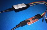
For charging
In Fig. 9 is a diagram of the simplest ISN with PWM, suitable for charging a phone, smartphone, tablet (a laptop, unfortunately, will not pull) from a homemade solar battery, wind generator, motorcycle or car battery, magneto flashlight-"bug" and other low-power unstable random sources power supply. See the diagram for the input voltage range, there is no error. This ISN is indeed capable of outputting a voltage greater than the input voltage. As in the previous one, here there is the effect of reversing the polarity of the output relative to the input, this is generally a proprietary chip of PWM circuits. Let's hope that after reading carefully the previous one, you will figure out the work of this little one yourself.

Along the way about charging and charging
The charging of batteries is a very complex and delicate physicochemical process, violation of which reduces their resource by several times and tens of times, i.e. number of charge-discharge cycles. The charger must, based on very small changes in the battery voltage, calculate how much energy is received and adjust the charge current accordingly according to a certain law. Therefore, the charger is by no means a power supply unit and you can only charge a battery in devices with a built-in charge controller: phones, smartphones, tablets, and individual models of digital cameras. And charging, which is a charger, is a subject of a separate conversation.
Voprosy-remont.ru said:
There will be sparks from the rectifier, but perhaps it's okay. The point is the so-called. differential output impedance of the power supply. In alkaline batteries, it is of the order of mΩ (milliohm), in acidic ones it is even less. For a trance with a bridge without smoothing - tenths and hundredths of ohms, i.e. approx. 100 - 10 times more. And the starting current of the collector DC motor can be more than the working current by 6-7 or even 20 times. Yours is most likely closer to the latter - fast-accelerating motors are more compact and more economical, and the huge overload capacity of the batteries allows you to give the engine current how much it will eat overclocking. A trans with a rectifier will not give so much instantaneous current, and the motor accelerates more slowly than it is designed for, and with a large armature slip. From this, from a large slip, a spark arises, and then it is kept in operation due to self-induction in the windings.
What can you advise here? First: take a closer look - how does it spark? You need to look at work, under load, i.e. during sawing.
If the sparkles dance in certain places under the brushes, it's okay. I have a powerful Konakovskaya drill from birth so sparkles, and even henna. For 24 years I changed the brushes once, washed it with alcohol and polished the collector - that's all. If you have connected an 18 V instrument to the 24 V output, slight arcing is normal. Unwind the winding or extinguish the excess voltage with something like a welding rheostat (a resistor of approx. 0.2 Ohm for a dissipated power of 200 W) so that the motor has a nominal voltage in operation and, most likely, the spark will go away. If you connected to 12 V, hoping that after rectification it would be 18, then in vain - the rectified voltage under load sits down a lot. And the collector electric motor, by the way, does not care whether it is powered by direct current or by alternating current.
Specifically: take 3-5m steel wire with a diameter of 2.5-3mm. Roll into a spiral with a diameter of 100-200 mm so that the turns do not touch each other. Place on a non-combustible dielectric pad. Strip the ends of the wire to a shine and roll up the "ears". It is best to immediately grease with graphite grease so as not to oxidize. This rheostat is included in the break of one of the wires leading to the instrument. It goes without saying that the contacts must be screw, tightly tightened, with washers. Connect the entire circuit to the 24V output without rectification. The spark is gone, but the power on the shaft has also dropped - the rheostat needs to be reduced, switch one of the contacts 1-2 turns closer to the other. It still sparks, but less - the rheostat is too small, you need to add turns. It is better to immediately make the rheostat known to be large, so as not to screw on the additional sections. It is worse if the fire is along the entire contact line of the brushes with the collector or spark tails are trailing behind them. Then the rectifier needs a smoothing filter somewhere, according to your data, from 100,000 uF. An expensive pleasure. The "filter" in this case will be the energy storage for the motor acceleration. But it may not help - if the overall capacity of the transformer is not enough. Efficiency of DC collector motors approx. 0.55-0.65, i.e. trance is needed from 800-900 watts. That is, if the filter is installed, but still sparks with fire under the entire brush (under both, of course), then the transformer does not hold out. Yes, if you put a filter, then the diodes of the bridge must also have a triple operating current, otherwise they can fly out from the charge current surge when connected to the network. And then the tool can be launched 5-10 seconds later after being connected to the network, so that the "banks" have time to "pump up".
And worst of all, if the tails of sparks from the brushes reach or almost reach the opposite brush. This is called an all-round fire. It very quickly burns out the collector until it is completely unusable. There can be several reasons for the all-round fire. In your case, the most likely one is that the motor was switched on at 12V with rectification. Then, at a current of 30 A, the electric power in the circuit is 360 W. The slide of the armature goes more than 30 degrees per revolution, and this is necessarily a continuous all-round fire. It is also possible that the motor armature is wound with a simple (not double) wave. Such electric motors are better able to overcome instantaneous overloads, but they have a starting current - mom, do not worry. More precisely, I can’t say in absentia, and I don’t need anything - there’s hardly anything fixable here with my own hands. Then, probably, it will be cheaper and easier to find and purchase new batteries. But first try to turn on the engine at a slightly increased voltage through the rheostat (see above). Almost always in this way it is possible to shoot down a solid all-round fire at the cost of a small (up to 10-15%) decrease in shaft power.
Beginner radio amateurs competition
"My radio amateur design"
The design of a simple laboratory power supply unit on transistors from "0" to "12" volts, and a detailed description of the entire manufacturing process of the device
Competitive design of a novice radio amateur:
"Regulated power supply 0-12 V on transistors"
Hello dear friends and guests of the site!
I present to your judgment the fourth competitive work.
The author of the design - Folkin Dmitry, city of Zaporozhye, Ukraine.
Regulated power supply 0-12 V on transistors
I needed a power supply unit adjustable from 0 to ... B (the more, the better). I reviewed several books and settled on the design proposed in Borisov's book "Young radio amateur". Everything is very well painted there, just for a novice radio amateur. In the process of creating such a complex device for me, I made some mistakes, the analysis of which I made in this material. My device consists of two parts: an electrical part and a wooden case.
Part 1. The electrical part of the power supply unit.
Picture 1 - Schematic diagram of the power supply from the book
I started by selecting the necessary parts. I found some of them at home, and bought others on the radio market.
Figure 2 - Electrical parts

In fig. 2 presents such details:
1 - voltmeter showing the output voltage of the PSU (I bought an unnamed voltmeter with three scales, to which a shunt resistor must be selected for correct readings);
2 - power supply plug of the power supply unit(I took the charger from Motorola, took out the board, and left the plug);
3 - a light bulb with a socket, which will serve as an indicator that the power supply unit is connected to the network (a 12.5 V 0.068 A light bulb, two of which I found in some old radio);
4 - switch from the power strip for a computer (there is a light bulb inside it, unfortunately, I had a burned out one);
5 - resistor 10 kOhm variable control group A, i.e. with a linear functional characteristic and a handle to it; needed to smoothly change the output voltage of the PSU (I took the SP3-4am, and the handle is from the radio);
6 - red "+" and black "-" terminals used to connect the load to the power supply unit;
7 - fuse 0.5 A installed in clips on the legs (I found a 6T500 glass fuse with four legs in an old radio);
8 - step-down transformer 220 V / 12 V also on four legs (you can use TVK-70; I had no marking, but the seller wrote "12V" on it);
9 - four diodes with a maximum rectified current of 0.3 A for a rectifier diode bridge (you can D226, D7 series with any letter or a KTs402 rectifier unit; I took D226B);
10 - medium or high power transistor with a radiator and a fixing flange (you can P213B or P214 - P217; I took P214 right away with a radiator, so as not to get warm);
11 - two electrolytic capacitors of 500 uF or more, one 15 V or more, the second 25 V or more (you can K50-6; I took K50-35 both for 1000 uF, one 16 V, the second 25 V);
12 - zener diode with a stabilization voltage of 12 V(you can D813, D811 or D814G; I took D813);
13 - low-power low-frequency transistor(you can MP39, MP40 - MP42; I have MP41A);
14 - constant resistor 510 Ohm, 0.25 W(MLT is possible; I took the SP4-1 trimmer for 1 kOhm, because its resistance will have to be selected);
15 - constant resistor 1 kOhm, 0.25 W(I came across a high-precision ± 1%);
16 - constant resistor 510 Ohm, 0.25 W(I have MLT)
Also for the electrical part I needed:
- one-sided foil textolite(fig. 3);
– homemade mini drill with drills with a diameter of 1, 1.5, 2, 2.5 mm;
- wires, bolts, nuts and other materials and tools.
Figure 3 - On the radio market I came across a very old Soviet textolite

Further, measuring the geometric dimensions of the existing elements, I drew the future board in a program that does not require installation. Then I took up the manufacture of a printed circuit board using the LUT method. I did it for the first time, so I used this video tutorial _http: //habrahabr.ru/post/45322/.
Stages of manufacturing a printed circuit board:
1 ... I printed out the drawn board in a printing house on a laser printer on glossy paper 160 g / m2 and cut it out (Fig. 4).
Figure 4 - Image of tracks and arrangement of elements on glossy paper

2 ... I cut off a piece of textolite measuring 190x90 mm. In the absence of scissors for metal, I used ordinary clerical scissors, it was cut long and hard. With the help of zero-grade sandpaper and 96% ethanol, I prepared the textolite for toner transfer (Fig. 5).
Figure 5 - Prepared foil textolite

3 ... First, with the help of an iron, he transferred the toner from the paper to the metallized part of the PCB, heated it for a long time, about 10 minutes (Fig. 6). Then I remembered that I also wanted to make silk-screen printing, i.e. drawing a picture on the board from the side of the parts. I put a piece of paper with a picture of the details on the non-metallized part of the PCB, warmed up for a short time, about 1 minute, it turned out not good. Still, first it was necessary to silk-screen, and then transfer the tracks.
Figure 6 - Paper on PCB after heating with an iron

4 ... Next, you need to remove this paper from the surface of the PCB. I used warm water and a shoe brush with metal fibers in the middle (fig. 7). I wiped off the paper very diligently. It may have been a mistake.
Figure 7 - Brush for footwear

5 ... After washing off the glossy paper, in Figure 8, you can see that the toner is transferred, but some of the tracks are torn. This is probably due to the hard work of the brush. Therefore, I had to buy a marker for CD / DVD discs and add them to almost all the tracks and contacts manually (Fig. 9).
Figure 8 - Textolite after toner transfer and paper removal

Figure 9 - Tracks drawn with a marker

6 ... Next, you need to etch unnecessary metal from the PCB, leaving the drawn tracks. I did it like this: I poured 1 liter of warm water into a plastic bowl, poured half a jar of ferric chloride there and stirred it with a plastic teaspoon. Then I put there a foil-clad textolite with marked tracks (Fig. 10). On a jar with ferric chloride, the promised etching time is 40-50 minutes (Fig. 11). After waiting for the specified time, I did not find any changes on the future board. Therefore, he poured all the ferric chloride that was in the jar into the water and stirred it. During the etching process, I stirred the solution with a plastic spoon to speed up the process. It took a long time, about 4 hours. To speed up the etching, it would be possible to heat the water, but I did not have this opportunity. Ferric chloride solution can be restored with iron nails. I didn't have them, so I used thick bolts. The copper settled on the bolts, and a precipitate appeared in the solution. I poured the solution into a three-liter plastic bottle with a thick neck and put it in the closet.
Figure 10 - PCB blank floats in ferric chloride solution

Figure 11 - Ferric chloride jar (weight not specified)

7 ... After etching (Figure 12), I gently washed the board with warm water and soap and removed the toner from the tracks with ethyl alcohol (Figure 13).
Figure 12 - Textolite with etched tracks and toner

Figure 13 - Textolite with etched paths without toner

8 ... Then I started drilling holes. For this I have a homemade mini-drill (Fig. 14). To make it, I had to disassemble an old broken Canon i250 printer. From there I took a 24 V, 0.8 A motor, a power supply for it and a button. Then on the radio market I bought a collet chuck for a 2 mm shaft and 2 sets of drills with a diameter of 1, 1.5, 2, 2.5 mm (Fig. 15). The chuck is put on the motor shaft, the drill with the holder is inserted and clamped. On top of the motor, I glued and soldered a button that powers the mini-drill. The drills are not particularly amenable to centering, so they are a little "guided" around the sides when working, but you can use them for amateur purposes.
Figure 14 -

Figure 15 -

Figure 16 - Drilled board

9 ... Then I cover the board with flux, smearing it with a thick layer of pharmacy glycerin using a brush. After that, you can tin the tracks, i.e. cover them with a layer of tin. Starting with wide tracks, I drove a large drop of solder on a soldering iron along the tracks until I completely tinned the board (Fig. 17).
Figure 17 - Tinned board

10. At the end, I assembled the parts on the board. I started with the most massive transformer and radiator, and ended with transistors (I read somewhere that transistors are always soldered at the end) and connecting wires. Also at the end of installation in the open circuit of the Zener diode, marked in Fig. 1 with a cross, I turned on the multimeter and selected such a resistance of the SP4-1 trimming resistor so that a current of 11 mA was established in this circuit. Such adjustment is described in Borisov's book "Young radio amateur".
Figure 18 - PCB with parts: bottom view

Figure 19 - PCB with parts: top view

Figure 18 shows that I misunderstood a little with the location of the holes for mounting the transformer and radiator, I had to drill. Also, almost all the holes for radio components turned out to be slightly smaller in diameter, because the legs of the radio components did not fit. Perhaps the holes became smaller after tinning with solder, so they should be drilled after tinning. Separately, it must be said about the holes for the transistors - their location also turned out to be wrong. Here I had to draw the diagram more carefully and thoroughly in the Sprint-Layout program. When positioning the base, emitter and collector of the P214 transistor, I should take into account that the radiator is installed on the board with its lower side (Fig. 20). To solder the leads of the P214 transistor to the desired tracks, I had to use copper pieces of wire. And the transistor MP41A had to bend the base output to the other side (Fig. 21).
Figure 20 - Holes for the terminals of the P214 transistor

Figure 21 - Holes for the terminals of the MP41A transistor

Part 2. Manufacturing of a wooden PSU case.
For the case, I needed:
- 4 plywood boards 220x120 mm;
- 2 plywood boards 110x110 mm;
- 4 pieces of plywood 10x10x10 mm;
- 4 pieces of plywood 10x10x15 mm;
- nails, 4 tubes of super glue.
Stages of manufacturing the case:
1 ... First, I sawed a large piece of plywood into planks and pieces of the required size (fig. 22).
Figure 22 - Sawed plywood boards for the cabinet

2
... Then I drilled a hole for the wires to the power supply plug using a mini-drill.
3
... Then I connected the bottom and side walls of the case with nails and superglue.
4
... Then I glued the internal wooden parts of the structure. Long posts (10x10x110 mm) are glued to the bottom and sides, holding the side walls. I glued small square pieces to the bottom, on which the printed circuit board will be installed and fastened (Fig. 23). Also inside the plug and on the back of the case, I fixed the wire holders (fig. 24).
Figure 23 - Case: front view (glue stains visible)

Figure 24 - Case: side view (and here the glue makes itself felt)

5 ... On the front panel of the case were carried out: a voltmeter, a light bulb, a switch, a variable resistor, two terminals. I needed to drill five round holes and one rectangular hole. It took a long time, since the necessary tools were not available and I had to use what was at hand: a mini drill, a rectangular file, scissors, sandpaper. In fig. 25 you can see a voltmeter, to one of the contacts of which a shunt trimming resistor of 100 kOhm is connected. Experimentally, using a 9 V battery and a multimeter, it was found that the voltmeter gives correct readings with a shunt resistance of 60 kOhm. The bulb holder is perfectly glued to the superglue, and the switch is well fixed in the rectangular hole even without glue. The variable resistor is well screwed into the tree, and the terminals are fixed on nuts and bolts. I removed the illuminating light from the switch, so there are two contacts on the switch instead of three.
Figure 25 - The insides of the PSU

After fixing the board in the case, installing the necessary elements on the front panel, connecting the components with wires and attaching the front wall with superglue, I got a ready-made functional device (Fig. 26).
Figure 26 - Ready PSU

In fig. 26, you can see from the color that the light bulb is different, not the one that was selected initially. Indeed, when a 12.5 V light bulb designed for a current of 0.068 A was connected to the secondary winding of the transformer (as indicated in the book), it burned out after a few seconds of operation. Probably due to the high current in the secondary winding. It was necessary to find a new place for attaching the light bulb. I replaced the light bulb with a whole one of the same parameters, but painted in dark blue (so that my eyes would not be dazzled) and with the help of wires I soldered it in parallel after the capacitor C1. Now it works for a long time, but the book indicates the voltage in that circuit is 17 V and I'm afraid I will have to look for a new place for the light bulb again. Also in fig. 26 shows that a spring is inserted into the switch from above. It is necessary for the reliable operation of the button that was dangling. The handle on a variable resistor, which changes the output voltage of the PSU, has been shortened for better ergonomics.
When turning on the power supply unit, I check the readings of the voltmeter and multimeter (Fig. 27 and 28). The maximum output voltage is 11 V (1 V has gone somewhere). Then I decided to measure the maximum output current and when the maximum limit of 500 mA was set on the multimeter, the arrow went off scale. This means that the maximum output current is slightly higher than 500 mA. When smoothly turning the handle of the variable resistor, the output voltage of the power supply also smoothly changes. But the change in voltage from zero does not start immediately, but after about 1/5 of a turn of the handle.
So, having spent a significant amount of time, effort and finances, I nevertheless assembled a power supply unit with an adjustable output voltage of 0-11 V and an output current of more than 0.5 A. If I can, then someone else can. Good luck to all!
Figure 27 - Power supply check

Figure 28 - Checking the correctness of the voltmeter readings

Figure 29 - Setting the output voltage to 5 V and checking with a control lamp

Dear friends and guests of the site!
Do not forget to express your opinion on the entries and take part in discussions on the site's forum. Thanks.
Design applications:
(15.0 KiB, 1,658 hits)
(38.2 KiB, 1,537 hits)
(21.0 KiB, 1,045 hits)