For a long time I was going to buy some kind of universal radio receiver / radio scanner in order to climb the air, listen to what the seasoned and bearded radio amateurs are talking about at night ...
Until recently, this pleasure cost from $ 300 to infinity. Well, with the transition of government agencies (both in Russia and abroad) to digital (but not yet encrypted) APCO P25 communication, the cost of satisfying unhealthy curiosity has become even higher.
A year ago, everything changed - the craftsmen found out that many of the Chinese USB TV tuners we sell for 600 rubles are in fact a universal radio receiver, on which you can listen to almost anything in the range of 50-900 MHz without any modifications (if you are lucky - up to 2200 MHz, but they don't convey anything in a voice): negotiations between airplanes with dispatchers, builders, taxis, bugs in your apartment and much more.
Under the cut I will tell you what and where to buy, how to connect and configure, and finally - what you can listen to.
Iron
The USB TV tuner consists of two parts - the radio frequency part (determines the possible frequencies of operation) and the digital part (digitizes the signal and transmits it to the computer via USB).One digital part is supported - RTL2832.
There are several options for the analog part: Elonics e4000 (everyone's favorite, works in the range of 50-1100Mhz and 1250-2200Mhz), FC0013 (~ 45-900Mhz). FC0012 is worse because has problems with signal quality and many frequencies where it does not work.
Thus, it is better to look for receivers with e4000 or FC0013. Unfortunately Elonics has gone bankrupt at this point and the last stocks are running low.
From trusted sources, I can note Dealextreme - they ran out of receivers on the e4000, and now they are going to FC0013.The full list of online stores is collected, well, in general, there is a lot of information on http://www.reddit.com/r/RTLSDR/. In case of purchase on ebay / aliexpress - necessarily check with the seller on which microcircuits their tuner is made (because very often they run out of them and they send others): "Hi, could you confirm that your tuner have rtl2832 & FC0013 (e4000) chips?", then if they send you not that - it will be easier to get the money back.
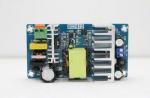
Inside, the receiver looks like this: 
On many models, the protective diode is "forgotten" (it protects the receiver from static electricity) - you can leave it as it is, but try not to touch the antenna with your hands, and disconnect the antenna from the receiver in a thunderstorm. But you can, of course, solder it yourself: BAV99 or, as in my case, 2 separate 1N4148s (one from the ground to the antenna, the other in the opposite direction. You need a "fast" diode with a small capacity, whatever will not work).
Antenna
An omnidirectional TV antenna MV-DMV ("horns") is quite suitable. I generally took a half-meter metal pin. All this needs to be pulled out onto the balcony / out the window. If the computer is far away, it is better to extend the USB cable rather than the antenna. Well, it is better to remove sources of radio frequency noise further away (for example, the same computer with an open case interferes greatly).
Software
There are a whole bunch of software options, I will consider a popular and quite convenient option - SDR # under Windows (you can also read in English):1) Download the latest version of SDR # Dev and SDR # RTLSDR Plugin, and the RTLSDR library.
2) Unpack SDR # Dev and SDR # RTLSDR Plugin into one directory. From the RTLSDR library, put the rtlsdr.dll file in the same directory (it is in the archive in the x32 directory). From the config subdirectory, move the SDRSharp.exe.config file to a higher level (where the bulk of the files turned out).
3) - a program to replace the tuner driver, which can only display a TV set, with a universal driver. We unpack it into the same heap.
4) Run Zadig.exe, click Options-> List all devices, select Builk-in, Interface 0, select the replacement driver - "WinUSB", click Reinstall Driver, agree with everything.
5) Run SDRSharp.exe, on the left side there will be an inactive Frontend button, and opposite it there will be a drop-down menu. Select RTL-SDR / USB there, and click Play in the upper left corner. Something should already start working.
6) Now you can either directly drive the desired frequency into the input field at the top left, or drag the frequency scale left-right to tune to the desired frequency.
Do you want to do something of your own? (e.g. GPS)
In the simplest case, you can get access to the ether like this:rtl_sdr -f 1575520000 -g 34 -s 2048000 out.dat
And in the file out.dat - the contents of the air are merged at a frequency of 1.575 GHz, with a sampling rate of 2.048 MHz with a gain of 34 dB. If the resulting file is now, for example, fed to the Matlab script from here, you can see the gps satellites (unless, of course, you connected an active GPS antenna to the receiver).
I got it like this (satellites - really correspond to those visible in the window on a regular gps receiver): 
What and where you can listen (in Moscow)
88-115Mhz - banal FM radio, WFM mode.118-135Mhz - communication between aircraft and dispatchers, AM mode.
433Mhz, 446Mhz - heaps of portable radios, builders usually have NFM.
144-145Mhz, 435Mhz - radio amateurs (there is practically no one in the day / morning), NFM.
864Mhz - a bunch of taxi channels, NFM.
You can also find "baby monitors", old analog cordless phones, with analog bugs listening to you - but here you can't guess with the frequency (all this is usually also in NFM).
But what about the digital communication APCO P25?
Downloading DSD. The program accepts the digital transmission on the default recorder, and plays the decoded result to the default playback device. To "connect" SDR # and DSD you need Virtual Audio Cable. We make in the Windows sound properties "output" VAC - the default recording device, and in SDR # select the playback device - Line 1 (VAC). AF Gain is about 20-40%. We tune SDR # to the desired frequency (Google knows which one) in NFM mode, a text with debugging information should run in the DSD window, and you should hear decoded conversations in the headphones. I strongly recommend not to record or distribute conversations overheard by chance.In a similar way (using VAC), programs are connected to decode pager messages, photos from weather satellites and other things.
Where to go next?
The improvement paths are as follows:1) HF converter to shift frequencies by 100MHz "up" - then you can listen to 27MHz walkie-talkies, and a bunch of suspicious spy HF stations and much more.
2) GaAs preamplifier: The e4000 is a silicon chip and is quite noisy. If you put a low-noise amplifier in front of it, you can reduce the noise level by about 3dB (i.e., by half).
3) Discone antenna - distinguished by its broadband and horizontal radiation pattern.
4) Broadcast notch filter (so that multi-kilowatt FM and TV stations interfere with the receiver less)
5) A band antenna for the range that interests you, instead of a discocone with a wide band, but weak gain (again, a band is narrower - the receiver has to filter out less extraneous signals - therefore, the reception quality of weak signals is potentially higher). Thanks for the last 2 points
Hello members of the forum! I decided to create my first topic on this forum.
I will tell you how to spend time and some money with interest and get a universal radio receiver in the range of 50-900 MHz. I met the $ 20 now, maybe cheaper. Last year, I bought a USB TV tuner on ebay, the seller no longer sells, but you can find it in the search for the Realtek rtl2832 Elonics e4000 chip.
Here is such a Chinese yusb TV tuner.
Ask? This is a tv tuner how to make a radio receiver.
There is nothing to solder. I will say
Downloading a patched driver with a radio function. convenient proven option - SDR https: //public-xrp.s...ase-rev427T.zip With auto tuner function.
To make it work as a radio receiver, we do not need native drivers, we replace them with the necessary patched ones.
Let's download the program for replacing firewood, drag it into the downloaded patch. (Open both and drag it)
Run Zadig.exe, click Options-> List all devices, select Builk-in, Interface 0, select the replacement driver - "WinUSB", click Reinstall Driver ![]()
Replaced? Move on.
And run our patch, the downloaded SDR file, open the Release folder-> click SDRSharp.exe, the application will open, click Other and the drop-down menu RTL-SDR / RTL2832U
Where to poke. 
Did you manage? We press the long-awaited Play if everything is done correctly, it should work.
Now you can drag the scale to the left or right, or drive it into the box from the top left.
My kit comes with a half-meter antenna.
It catches better on a home antenna. Horn systems. On some, the protective diode is forgotten, so as not to kill the receiver, we do not touch the antenna with our hands.
Does the zomboy show? Whistle DVB-T format. in my area DVB-T2. So I won't say anything about the TV set.
What can you hear taxi drivers, radio amateurs, builders, communication between aircraft and dispatchers, FM radio.
Especially for smart people I tried to briefly describe the process. Chewed on habrahabr!
Your true noob
Kendi bober
Don't forget Google knows everything
This device is based on a TV tuner, DDS synthesizer and an additional pairing scheme.
The receiver turned out to be so strong that you can use it for long-range reception!
This receiver will operate from 45 to 860 MHz and the step size can be up to 0.01 Hz.
Why not use this receiver as a spectrum analyzer or NOAA satellite receiver?
Next, about it!
Any contributions to the creation and addition of this page are of great importance!
Small digression
Why make life harder than it really is? 
My main idea for this project was: why not use a tuner when building a receiver? Said and did. The heart of this receiver is the tuner from your TV or VCR. The tuner is digitally controlled, which means the frequencies must be programmed via the I2C interface.
Don't quit reading now! It's not difficult at all and I have everything ready for you, so keep reading. The smallest tuning steps are 31.25kHz, 50kHz or 62.5kHz. This is too large a step, especially if you are doing low frequency reception. To address this issue, I added a second mixer using a DDS synthesizer as the LO. With DDS, you can immerse yourself in the virtual world of the air through a 62.5kHz, 50kHz or 31.25kHz window. The smallest tuning step with this design can be from 0.01 Hz. In most cases, the 0.01 Hz step will be small, so in my program I will use the smallest 1 Hz step.
Initial information about the TV tuner
I just love TV tuners, and so now I will explain to you how they work.
I wrote earlier about tuners, but it is impossible to write a lot about them, and that's why, let's repeat:
What does a tuner look like?
Open your VCR or TV and find a shiny methalic box. If you find it, you can open it, and you will see hundreds of bugs inside it. These are surface mount components.
Tuners are based on downconversion. The RF signal is downconverted to an IF frequency of 34-38.9MHz (European standard). Some newer tuners have an internal demodulator and output video and audio signals.
The output frequency you want can be set in two ways: analog or digital.
Input bandwidths:
VLF-48-180MHz
VHF 160-470MHz
UHF430-860MHz
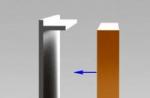
Analog tuners use a 0-28V input voltage to drive the VCO (VCO, Voltage Controlled Oscillator), and there are 3 pins for  range selection (see fig). Voltage Tuning also controls the resonance frequency of the tuner's input filter. The signal from the RF input is mixed with the VCO signal and the final conversion product (IF) 38.9MHz is formed at the output.
The disadvantage of an analog tuner is that it is difficult to obtain a stable VCO tuning voltage and determine the current tuning frequency.
The digital tuner works differently. It uses a PLL (Frequency Synthesizer) to set the frequency. The synthesizer can be programmed to any frequency in the range from 45 to 860MHz. The tuner frequency synthesizer compares the VCO frequency with the programmed frequency. The circuit changes the voltage settings until the VCO frequencies and the reference frequency are in phase.
Bands and frequency are programmable via the I2C interface. The digital tuner adheres to the target frequency very accurately and is very stable. The only drawback with this type of tuner is that you need digital logic to program the tuner. I usually use a PIC controller to control my digital tuners.
Let's take a look at some tuners: UV916 and noname tuner
In most cases, you will find it difficult to find the designation label on the tuner. I don't know why manufacturers are so disgusting about labeling tuners. I have collected over 50 tuners from various TVs and VCRs and I only managed to find about 10 with the correct label. Do not worry! Even if you cannot find any information about the tuner, you can open it and identify it by the diagram. Most often you will find a PLL synthesizer and one demodulator / mixer. Try to find a datasheet on the PLL, and you will understand how to program the tuner.
One of the common UV916 tuners. Pictured is UV916H / UV916 E-tuner. I will help you identify it.

This tuner is based on two microcircuits. TDA5630 "9 V VHF, hyperband and UHF mixer / oscillator for TV and VCR 3-band tuners" and TSA5512 "1.3 GHz Bidirectional I2C-buscontrolled synthesizer".
The TSA5512 is programmed to the desired frequency and sets the Vtuning PLL voltage located in the TDA5630 circuitry.
The tuning step of this tuner is fixed at 62.5kHz. This tuner has 9 pins and a ground cover.
AGC = AGC automatic gain control. A voltage from 0 to 12V will control the gain of the preamplifier.
+ 12V = power supply for preamplifier and TDA5630 circuit.
+ 33V = PLL tuning voltage power supply.
+ 5V = PLL synthesizer power supply.
SCL = I2C clock PLL synthesizer.
SDA = I2C data to the PLL synthesizer.
AS = Address selection for tuner (used with MA1 and MA0 see page 8 of datasheet)
IF = IF output
IF = IF output
Quite a difficult task in tuners is to establish the desired range. The ranges are selected by programming the port registers P0 ... P7 in the TSA5512 circuit. UV916 range correspond to the following table:
| BAND | P7 | P6 | P5 | P4 | P3 | P2 | P1 | P0 |
| LOW BAND (60h) | 0 | 1 | 1 | 0 | 0 | X | X | X |
| MID BAND (50h) | 0 | 1 | 0 | 1 | 0 | X | X | X |
| HIGH BAND (30h) | 0 | 0 | 1 | 1 | 0 | X | X | X |
Noname tuner
Now, let's try to identify the components of the unnamed tuner at my disposal. 
After removing the cover, we will see two circuits: the TDA 5630, which is a mixer and VCO, and the TSA5522, a PLL synthesizer. Looking at the datasheet, we can find comprehensive information. Guided by the TSA5522 datasheet and following the tracks on the board, we can easily find the SCL and SDA inputs. We can also find pin P6, which is the input of a 5-level ADC converter that can be used for automatic frequency control (AFC). We will apply AFC (automatic frequency control). In most cases, you can skip this input and leave it hanging freely. You can also find the entrance marked AS. By choosing a specific voltage, you can choose one of three synthesizers that can be present in the system. In most cases, you will be using one tuner, so you can leave this input free hanging as well.
The frequency synthesizer circuit is powered by + 5V, while consuming a small current. By looking at page 13 of the datasheet, you can understand how the synthesizer works. The PLL uses + 33V at the CP input as the tuning voltage for the varicaps. Following the tracks on the board, I managed to find the 33V DC input.
Looking at the datasheet of the TDA5630 microcircuit, we can find that it is powered by + 9V, and, guided by this level, we find the corresponding block output. The last of the block pins is not listed in the datasheet, it is called AGC (automatic gain control, AGC). With this pin, you can control the RF preamplifier by changing its gain. A good solution is to set the level on this pin to half the system supply voltage, i.e. 6V, using a divider of two resistors. Most often, you will find the AGC pin on the first pin closest to the RF input.
Now we know the purpose of all the conclusions of this incomprehensible tyer. Read the datasheets to understand the logic behind the PLL TSA5522.

Do not be intimidated by the large number of filters and mixers, within a few minutes you will understand what's what.
The tuner belongs to the digital class, whose frequency is controlled by applying a control signal to the I2C bus. The smallest tuning step of the tuner is 62.5 kHz.
For an easier understanding of the principles of work, look at the figure. There are 2 handles at your disposal.  The left (red) controls the tuning of the tuner with a step of 62.5 kHz. The right one controls DDS, which can be tuned in 0.01 Hz steps from 0 to 62.49999 kHz. In the example, I determined the step of tuning this generator as 1 Hz. The formula below shows you how you can use these two switches to any desired frequency. In fact, the DDS frequency does not lie in the range from 0 to 62.49999 kHz at all, its values range from 5.01375 MHz to 5.07625 MHz).
With these two components (tuner and DDS), you can scan the entire 45-860 MHz range in 0.011 Hz steps! To understand how the tuner works, I describe each block. The IF (intermediate frequency) output is set to 37 MHz, which is the European standard. A SAW filter cuts out-of-band conversion products. The signal, passing through the first mixer, is mixed with a fixed quartz oscillator frequency of 42.5 MHz.
The conversion product of the first mixer is 5.5 MHz. I use a standard 5.5 '' piezo ceramic filter to cut out out-of-band signals. The filter should have a bandwidth of 100 kHz, which is typical for TVs and VCRs.
Before looking at the 2nd mixer, pay attention to the end of the circuit where the detector is located. The detector operates at a frequency of 455 kHz, and in front of it there is a piezo-ceramic filter at this frequency. If we set the DDS frequency to 5.5 MHz - 455 kHz = 5.045 MHz, we get exactly the set receive frequency that we need. Remember I told you about the smallest tuning step of the 62.5 kHz tuner? The UV916 has a tuning step of 62.5 kHz!
Now, if we change the DDS frequency within ± 31.25 kHz, we can implement smooth tuning. DDS will then tune within 5.045 MHz ± 31.25 kHz.
The conditions for the operability of this scheme
It will work ideally if the bandwidth of the 5.5 MHz ceramic filter in front of the second mixer is wider than 62.5 kHz.
If the bandwidth is less than 62.5 kHz you will run into problems. In my test design (photo below), I found that the 3-pin filter has a bandwidth of 600 kHz, and the 4-pin filter has a bandwidth of about 350 kHz, which most likely will not create unnecessary problems. This is not very good at filtering out-of-band signals. less bandwidth will provide better sensitivity and selectivity.

After all this, you might think that the design contains a lot of mixers, filters and other shit ... Don't worry!
If you use the widely used MC13135 / 13136 microcircuit, you can only use it to implement a set of blocks of this circuit. It contains one crystal oscillator, two mixers, an FM modulator, an RF output and many other valuable priblud. You can find piezoelectric ceramics and a 455 kHz circuit in cheap receivers on microcircuits. SAW filter, 5.5 MHz piezo ceramic filter and tuner can be found in broken VCRs and TVs. I also think they can be found in a perfectly working technique. Why not pluck them out of a perfectly working widescreen TV?
9-stage DDS filter
I will describe in detail in several sections the Super-Scanner circuit for ease of perception.
Tuner block
For this design, I used the widely available UV916 tuner. The AGC voltage is set to + 6V using two resistors.
To power the device, I used three different power supplies (+5, +12 and +33 V). The I2C bus (SCL, SDA) is connected to the RB3 and RB4 pins of the PIC controller.
P3 remains suspended and the 37.0 MHz IF output is connected to the input of the SAW filter. The filter has two inputs and two outputs. The outputs are connected to the IF amplifier path. The bandwidth limits are 34-38.9 MHz. This helps to get rid of the mirror channel reception.
DDS block
The DDS is synchronized with a 50 MHz clock frequency using a crystal resonator. From the PIC of the controller, the control signals through RB5, RB6 and RB7 go to the DDS.
Chokes L1 and L2 filter the power supply voltage and separate the analog and digital parts.
The DDS output is terminated with 300 ohms and connected to a 9-way P-filter. The filter removes harmonics and out-of-band emissions generated by the digital part of the circuit.
After the filter, a beautiful harmonic signal of 5.045 MHz is obtained.
One of the difficulties in assembling this design is that, due to the presence of small components, you must use a sharpened soldering iron. Be calm and do not worry, soldering this baby ...
IF block
Assembled on MC33165. Conclusions 1 and 2 heterodyne. I used a quartz resonator circuit. On pin 3, the output of the local oscillator buffer stage is found. The signal filtered by the SAW is fed through pin 22 to the input of the first mixer. The transformation products are removed from the 20th leg. A 5.5 MHz piezo ceramic filter cuts off all signals +/- 100 kHz apart. The signal arrives at the input of the second mixer, where it mixes with the DDS signal arriving at the 6th leg. The conversion products pass through a 455 kHz filter to the FM detector.
A coil is connected to the quadrature detector through pin 13. From pins 15-16, you can remove the voltage level proportional to the input signal level in decibels. When using the receiver as a spectrum analyzer, you can connect this output to the Y input of an oscilloscope. The X input is connected to the frequency tuning voltage. Pin 17 audio output. The signal there has a value of 50-150 mV, which is quite small. I amplified it with the simple amp shown at the bottom of the circuit.
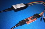
RS232 interface 
Now I will explain how the circuit works in conjunction with a computer. You don't have to delve into this if you don't want to, but some might want to write a program that controls the receiver. So I took care of everything!
I designed this receiver in such a way that its configuration could be completely controlled from a computer. Thus, you can make sure that the device is working even before connecting buttons, display, etc. to it. In the end, you can make a portable autonomous device, but first of all, let's make sure that it is fully operational, the shortest way to which is to connect it to a computer and check the correctness of counting and setting the required receiving frequency. In order to connect the device to a computer, it was necessary to introduce an RS interface into the circuit, assembled on a MAX232 microcircuit, which converts TTL levels to the COM port standard. I chose baud rate 19200, parity, 8 bits and 1 stop bit (19200, e, 8.1). Now let's take a look at the protocol.
The software I have written is unified. This means that you can use many different tuners with this software. First of all, you need to apply the required levels to 9 registers. Adressbyte assigns tuneradress for I2C. Dividerbyte 1 and 2 are used to set the tuner frequency.
Controlbyte is used to control PLL currents and other things, Portbytes selects the desired receive range. In document TSA5512.pdf you can find the principle of tuner register management. The function performed by the program is to calculate the values of these 9 registers and send them to the PIC controller. The PIC receives the information, translates it into the I2C bus protocol and sends it to the tuner and DDS. You don't need to understand what the PIC controller does, but you still need to figure it out to write the program.
To complete the receiver frequency tuning, you need to send 9 bytes to the PIC controller. The first 5 are used to control the tuner (yellow). The next 4 bytes (green) set the DDS frequency. You can read more information about DDS at this link. The above table shows 9 registers. When all information has been sent from the computer to the controller, make sure the tuner and DDS frequencies are set correctly.
Windows program
I wrote a simple program, the interface of which you can see in the screenshot.

Let me tell you about the purpose of buttons and windows.
Receiving Frequency
Receive frequency, here you can set the frequency you want to receive. Enter a value in the green box and click Set Freq. You can also set the step size for up / down scanning. The step is entered in the same way as the frequency.
Comport
Here you can set the desired COM port for communication.
Tuner register settings
Here you can set the values of the registers. Dividerbyte 1 and Dividerbyte 2 are calculated automatically depending on the received frequency in the Receiving Frequency box. Adressbyte, Controlbyte and Ports byte can be manually changed at any time. Each time you change the value, the program automatically sends data to the tuner.
Remember, when changing the frequency above 150 MHz and 450 MHz, you need to manually switch the Ports byte range, because the program does not know how to do this automatically.
DDS Setting
To set the DDS frequency, you need to know the Reference frequency of the given DDS. The output frequency is calculated based on the Reference frequency entered earlier. You will also see 32 bit DDS displayed as 4 bytes.
Buffer
The buffer displays 9 bytes sent to the PIC. When the Send button is pressed, the contents of the buffer are sent to the PIC via RS232 now. This also happens with any change in any of the values.
Let's look at the numbers above:
IF = Xtal - DDS - 455kHz => 42.5e6 - 5.02e6 - 455e3 = 37.025.000 Hz
Tuner VCO = 62500 * tuner divider => 62500 * 2274 = 142.125.000 Hz
RF receive = Tuner VCO - IF => 142.125e6 -37.025.e6 = 105.1 MHz
Look how great it is!
Well, that's all about the program.
Download PIC16F84 firmware (INHX8M format)
| s_tuner.zip | Super tuner program (the hex file is zipped!). |
Download datasheets
| TSA5512_CNV_3.pdf | Datasheets for TSA5512_CNV_3.pdf |
| SAW filter information and PDF download | SAW filter information and PDF download |
| I 2 C information | I 2 C Bus Technical Overview and FAQ |
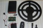
My performance of the Super Scanner.
I want you to see how I embodied everything in hardware.
Below is a photo of what I soldered late the night before.


The soldering is done by a combination of conventional elements and surface mounting.
I added a converter to the circuit to obtain a 33 V reference voltage.
I also added two (black and yellow) piezoceramic resonators at 455 kHz and a relay for switching them. I also added a relay to switch the signal amplification from the detector output. This is done by simply switching resistors in parallel with the coil of the quadrature detector. The reason that prompted me to make these improvements is that I wanted to receive both wideband and narrowband signals with the best quality.
Making and checking the circuit
Do not connect the inverter path until you have debugged all the other nodes. I recommend that you run DDS first. When you get a good signal from the DDS of the desired frequency, grab the tuner. Find the test point TP on the diagram. Connect a DC voltmeter to it and measure the voltage. It should change when the tuning frequency is changed. This is an easy way to make sure the tuner is working properly. Now turn on the inverter unit and check the frequency of the crystal oscillator. I hope everything worked well for you.
Final Words
This project will serve as a starting point for your tuner projects. This project can grow to almost biblical proportions. There are so many different keyboards and displays on the market that I decided to skip this part and just control the receiver from my computer.
You can write to me if something is unclear.
I wish you the best of luck with your projects, and thanks for visiting my page.
Offered to review the DVB-T tuner. I would refuse because of the outdated broadcast format, but the device itself is painfully entertaining. Using the tuner, you can receive and decode almost any signal in the range from 25 to 900 MHz. I also decided to listen to the broadcast for a bit.
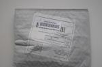
The tuner arrived in an unmarked gray box. Inside there is the device itself, a CD with software, a remote control and an antenna. Everything is in plastic bags.
The size of the tuner is slightly larger than a flash drive. An antenna is connected to the side. And through the holes, the signal of the IR remote control is received.


We open it immediately
The heart of the device is the RTL2832U chip, and the FC0012 chip is responsible for amplifying the RF signal. Instead of the latter, other microcircuits can be used, which affects the range of received frequencies, antenna sensitivity and requires the selection of appropriate drivers.

We are watching TV
Switching on and setting up is very simple. The tuner worked for me on Windows 7 and 10. There are drivers and a TV receiver on the CD, but you can find it on the Internet, if anything. I have not tested it on an OS of the Linux family, but the performance in this environment is confirmed by comments on the Internet. Moreover, I launched the tuner on my smartphone in just a couple of clicks.
The Blaze HDTV Player program is taken as the basis for watching TV channels. This is a paid app, although there is a serial number on the disc packaging. I took the most recent version from the official site (in demo mode). Scanning the range takes about two minutes, after which I have a list of channels. In Kiev for 2017, you can find 16 channels in the DVB-T range. (ERA | first national; Boutique; M2; TruthTut; PlusPlus; NEWS 24; Rti; 100+; Channel 5; NewsOne; EU Music; Music Box; Rada; Sonce; Nadiya; KRT;). 
With the same program you can listen to radio in the range of 88-108 MHz. 28 stations were found with confident reception. 
Unfortunately, for a reliable signal reception, I had to attend to the removal of the laptop with all the equipment on the balcony. It would be nice to use a decent-sized antenna, but for this you have to get hold of an adapter from the used MCX connector to a regular antenna connector. Otherwise, you can get slides instead of video stream. On the Internet, it is also recommended to touch the antenna less in order to avoid damage to the device by static.
I tried to collect statistics on signal reception in Kiev. Near the metro station Kharkovskaya - the reception is poor. At the Demievskaya metro station, the reception is good. Near the Minskaya metro station, the reception is of average quality; a larger antenna is needed. Let me remind you that television broadcasts are also carried out in the DVB-T2 range.
Alternative programs and drivers
First you need to attend to the replacement of device drivers. To do this, use the Zadig program, which can be found along with the downloaded software or on the website. On the above site, the installation instructions are shown in pictures. On my own I will add that to search for a device called RTL2838UHIDIR - in the program settings, it would be good to check the boxes opposite “List all devices” and “Ignore Hubs or Composite Parents”.
Most of all I liked the SDRSHARP program. ... I have not studied all of its settings, but in general, the ion is quite functional. Changing the frequency is carried out by pressing the upper or lower part of the digits of the displayed current frequency. The type of received signal is automatically selected based on the range. But almost everything can be picked up manually. With this program, I was able to receive a signal in the range of 21 MHz ... 
... up to 940 MHz. The FM band even showed RDS station information. 
If you need to change drivers to native ones from Realtek, then I found them here. Choose according to the chipset.
RTL2838U + E4000, FC0012, FC0013= Treiber1.zip
RTL2838U + R820T= Treiber2.zip
RTL2838U + Noxon= Treiber3.zip
RTL2838U + R828D= Treiber4.zip
Work via USB OTG on Android
For work, I needed a regular OTG cable. The tuner consumes very little, about 0.7W, so I'm calm about the smartphone's battery.

Going to the Play Market and specifying the phrase "RTL RDS" in the search, I found a lot of programs. I tested the first ones that came across. Scanned the range using the SDRTouch program (downloads the Rtl-sdr driver). And I watched TV through Aerial TV (downloads DVB-T driver). It turned out pretty well. 

Afterword
Despite the outdated DVB-T format, this tuner may well be needed both for watching TV channels and listening to the FM range, and for avid radio amateurs. The latter, I think, have already been heard for similar devices and their undocumented functions.Please forgive me for not testing the remote control.
The product is provided for writing a review by the store. The review is published in accordance with clause 18 of the Site Rules.
I plan to buy +40 Add to favourites I liked the review +43 +67 August 16, 2012 at 02:59 PMUSB TV tuners on rtl2832 - or how to hear everything on the air for 600 rubles
- Communication standards
For a long time I was going to buy some kind of universal radio receiver / radio scanner in order to climb the air, listen to what the seasoned and bearded radio amateurs are talking about at night ...
Until recently, this pleasure cost from $ 300 to infinity. Well, with the transition of government agencies (both in Russia and abroad) to digital (but not yet encrypted) APCO P25 communication, the cost of satisfying unhealthy curiosity has become even higher.
A year ago, everything changed - the craftsmen found out that many of the Chinese USB TV tuners we sell for 600 rubles are in fact a universal radio receiver, on which you can listen to almost anything in the range of 50-900 MHz without any modifications (if you are lucky - up to 2200 MHz, but they don't convey anything in a voice): negotiations between airplanes with dispatchers, builders, taxis, bugs in your apartment and much more.
Under the cut I will tell you what and where to buy, how to connect and configure, and finally - what you can listen to.
Iron
The USB TV tuner consists of two parts - the radio frequency part (determines the possible frequencies of operation) and the digital part (digitizes the signal and transmits it to the computer via USB).One digital part is supported - RTL2832.
There are several options for the analog part: Elonics e4000 (everyone's favorite, works in the range of 50-1100Mhz and 1250-2200Mhz), FC0013 (~ 45-900Mhz). FC0012 is worse because has problems with signal quality and many frequencies where it does not work.
Thus, it is better to look for receivers with e4000 or FC0013. Unfortunately Elonics has gone bankrupt at this point and the last stocks are running low.
From trusted sources, I can note Dealextreme - they ran out of receivers on the e4000, and now they are going to FC0013.The full list of online stores is collected, well, in general, there is a lot of information on http://www.reddit.com/r/RTLSDR/. In case of purchase on ebay / aliexpress - necessarily check with the seller on which microcircuits their tuner is made (because very often they run out of them and they send others): "Hi, could you confirm that your tuner have rtl2832 & FC0013 (e4000) chips?", then if they send you not that - it will be easier to get the money back.
Inside, the receiver looks like this:
On many models, the protective diode is "forgotten" (it protects the receiver from static electricity) - you can leave it as it is, but try not to touch the antenna with your hands, and disconnect the antenna from the receiver in a thunderstorm. But you can, of course, solder it yourself: BAV99 or, as in my case, 2 separate 1N4148s (one from the ground to the antenna, the other in the opposite direction. You need a "fast" diode with a small capacity, whatever will not work).
Antenna
An omnidirectional TV antenna MV-DMV ("horns") is quite suitable. I generally took a half-meter metal pin. All this needs to be pulled out onto the balcony / out the window. If the computer is far away, it is better to extend the USB cable rather than the antenna. Well, it is better to remove sources of radio frequency noise further away (for example, the same computer with an open case interferes greatly).Software
There are a whole bunch of software options, I will consider a popular and quite convenient option - SDR # under Windows (you can also read in English):1) Download the latest version of SDR # Dev and SDR # RTLSDR Plugin, and the RTLSDR library.
2) Unpack SDR # Dev and SDR # RTLSDR Plugin into one directory. From the RTLSDR library, put the rtlsdr.dll file in the same directory (it is in the archive in the x32 directory). From the config subdirectory, move the SDRSharp.exe.config file to a higher level (where the bulk of the files turned out).
3) - a program to replace the tuner driver, which can only display a TV set, with a universal driver. We unpack it into the same heap.
4) Run Zadig.exe, click Options-> List all devices, select Builk-in, Interface 0, select the replacement driver - "WinUSB", click Reinstall Driver, agree with everything.
5) Run SDRSharp.exe, on the left side there will be an inactive Frontend button, and opposite it there will be a drop-down menu. Select RTL-SDR / USB there, and click Play in the upper left corner. Something should already start working.
6) Now you can either directly drive the desired frequency into the input field at the top left, or drag the frequency scale left-right to tune to the desired frequency.
Do you want to do something of your own? (e.g. GPS)
In the simplest case, you can get access to the ether like this:rtl_sdr -f 1575520000 -g 34 -s 2048000 out.dat
And in the file out.dat - the contents of the air are merged at a frequency of 1.575 GHz, with a sampling rate of 2.048 MHz with a gain of 34 dB. If the resulting file is now, for example, fed to the Matlab script from here, you can see the gps satellites (unless, of course, you connected an active GPS antenna to the receiver).
I got it like this (satellites - really correspond to those visible in the window on a regular gps receiver):
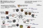
What and where you can listen (in Moscow)
88-115Mhz - banal FM radio, WFM mode.118-135Mhz - communication between aircraft and dispatchers, AM mode.
433Mhz, 446Mhz - heaps of portable radios, builders usually have NFM.
144-145Mhz, 435Mhz - radio amateurs (there is practically no one in the day / morning), NFM.
864Mhz - a bunch of taxi channels, NFM.
You can also find "baby monitors", old analog cordless phones, with analog bugs listening to you - but here you can't guess with the frequency (all this is usually also in NFM).
But what about the digital communication APCO P25?
Downloading DSD. The program accepts the digital transmission on the default recorder, and plays the decoded result to the default playback device. To "connect" SDR # and DSD you need Virtual Audio Cable. We make in the Windows sound properties "output" VAC - the default recording device, and in SDR # select the playback device - Line 1 (VAC). AF Gain is about 20-40%. We tune SDR # to the desired frequency (Google knows which one) in NFM mode, a text with debugging information should run in the DSD window, and you should hear decoded conversations in the headphones. I strongly recommend not to record or distribute conversations overheard by chance.In a similar way (using VAC), programs are connected to decode pager messages, photos from weather satellites and other things.
Where to go next?
The improvement paths are as follows:1) HF converter to shift frequencies by 100MHz "up" - then you can listen to 27MHz walkie-talkies, and a bunch of suspicious spy HF stations and much more.
2) GaAs preamplifier: The e4000 is a silicon chip and is quite noisy. If you put a low-noise amplifier in front of it, you can reduce the noise level by about 3dB (i.e., by half).
3) Discone antenna - distinguished by its broadband and horizontal radiation pattern.
4) Broadcast notch filter (so that multi-kilowatt FM and TV stations interfere with the receiver less)
5) A band antenna for the range that interests you, instead of a discocone with a wide band, but weak gain (again, a band is narrower - the receiver has to filter out less extraneous signals - therefore, the reception quality of weak signals is potentially higher). Thanks for the last 2 points